LC VCO Using Active Inductor for Low Phase
Noise and Wide Tuning Range
Ranjana Mehra1, R.C. Gurjar 2
P.G. Student, (Microelectronics and VLSI Design), Department of E&I, Shri G. S. Institute of Technology and Science,
Indore, M.P, India 1
Associate Professor, (Microelectronics and VLSI Design), Department of E&I, Shri G. S. Institute of Technology and
Science, Indore, M.P, India 2
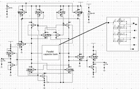
ABSTRACT:This paper presents the design of a resistor-less voltage controlled oscillator (VCO) with wide tuning range. The circuit consists of an active inductor, a 4-bit capacitor bank and two buffers. The main idea of the proposed VCO is to replace the passive inductor of the conventional VCO with an active inductor to achieve the less area and noise. The proposed circuit is implemented in a 0.18µm CMOS technology. The tuning range of proposed VCO is from 1.7GHz to 3.28GHz. This is achieved by varying the control voltage of VCO from 1V to 2.5V and by digitally controlling the 4- bit capacitor bank. It consumes 2.6mW dc power at 1.5V supply voltage. VCO has -103dBc/Hz phase noise at 1MHz offset frequency. To improve the phase noise, a parallel capacitor bank is used in place of single capacitor. This circuit is useful for high speed analog signal processing.
KEYWORDS:LC VCO, Phase Noise, Tuning Range, Active inductor, Capacitor Bank.
I.
INTRODUCTIONThe need of inductive characteristic is essential for high speed applications. The LC VCO has found applications in analog signal processing. In CMOS integrated technologies, a VCO can be used as a ring oscillator, an active inductor-capacitor (LC) oscillator, or a passive LC oscillator. A transmission-line resonator VCO can also be used for better phase-noise performance, but uses large-area of implementation. The positive feedback ring oscillators with odd number of stages are useful for wide tuning range application. But they have poor phase-noise performance and are not useful for communications applications.
The active LC oscillators are implemented by LC resonators as the frequency-determining elements and where inductors are implemented with the help of gyrator-C circuit structure. The active inductors have very large quality factors (Q). But the use of active inductor in oscillator increases noise contribution in circuit,compared to its passive counterpart, causes the phase noise of the oscillator to be relatively high, compared to its passive parts, and is therefore not suitable for low-noise design applications. To overcome this problem, the complementary cross-coupled trans-conductor active LC VCO is used because it provides less area of implementation on silicon chip with good phase noise performance. It also attractive for low-power design resulting from sharing the bias current between the NMOS and PMOS transconductors.
This paper is organized as follows. Section II discusses about the related work. Section III introduces proposed active inductor and LC oscillator based on it. Section IV presents the simulation results followed by the conclusion in section V.
II.
RELATED WORKFig 1. Proposed LC VCO based on Active Inductor and Cap bank
III.
PROPOSED ALGORITHMThe gyrator-C structure is used to make active inductor in the proposed circuit. The inductance of gyrator-C structure is given by
= … (1)
Equation (1) shows that the inductance of gyrator-C is directly proportional to the load capacitance C and inversely proportional to the transconductances of the transconductors of the gyrator.
In figure 1, two back to back connected Gm cells are used. M16, M7 are in common mode configuration and used as voltage buffers. To control the inductance of the active inductor, the transistor M32 and M1 are used which acts as PMOS current source. The variations of common mode signal in the terminal of inductor are reduced by transistor M0, M8, M14 and M18 are used which results lower phase noise in oscillator. The Vc is used to control the inductance of the circuit through transistors M18 and M0.Increasing the Vc, results lower gate voltage at M1 and M32 which increases their currents. Due to this, transconductance of M11 and M15 increases which results lower inductance and higher oscillation frequency.
The frequency of oscillation is given by
= 1
2 √ (2)
Where L= Inductance of active inductor
C= Equivalent capacitance of cap bank depending on the number of switches are on
IV.
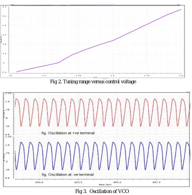
SIMULATION RESULTSThe active inductor VCO is simulated with 0.18 μm CMOS technology by using cadence software. Tuning range of the
oscillator versus control voltage is shown in Fig 2. It can be observed that there is a wide tuning range, from 436 MHz to 3.28 GHz which obtained by varying control voltage from 1.5Vto 2.5 V.
Fig 2. Tuning range versus control voltage
Fig 3. Oscillation of VCO
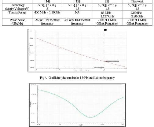
Table I
Comparison between different work on VCO
[14] [15] [2] This work
Technology 0.8μ m CMOS 0.2 μm CMOS 0.18μm CMOS 0.18μm CMOS
Supply Voltage (V) 3 1.8 1.8 1.8
Tuning Range 450 MHz – 1.16GHz NA 86 MHz –
1.137 GHz
436MHz – 3.28 GHz Phase Noise
(dBc/Hz)
-92 at 1 MHz offset frequency
-81 at 500KHz offset frequency
-102 at 1 MHz Offset Frequency
-103 at 1 MHz Offset Frequency
Fig 4. Oscillator phase noise in 1 MHz oscillation frequency
Fig 5. Total dc power variation with control voltage
V.
CONCLUSION AND FUTURE WORKIn this paper, a new active inductor is proposed to increase oscillation frequency of VCO and decrease the phase noise in gyrator– C structure. For this purpose, a common mode feedback technique is used. So the phase noise in an oscillator is reduced to -103 dBc/Hz. Proposed oscillator is tunable from 436 MHz to 3.28 GHz which is achieved by varying the control voltage of VCO from 1V to 2.5V. The circuit is simulated with 0.18μm CMOS technology by using
diode because it has a wide tuning range inductance. Also, it can be easily integrated with other MMIC circuits. This circuit can also be used with series varactor bank and a parallel capacitor bank.
REFERENCES
1. Sang-Ki Eun #1, Choon Sik Cho #2, Jae W. Lee #3 and Jaeheung Kim ∗4”A Low Power VCO Using Active Inductor For Low Phase Noise and Wide Tuning Range” Proceedings of the 39th European Microwave Conference IEEE, oct 2009
2. Mahdi Ebrahimzadeh, Farzan Rezaei, Siavash Rezaei “A New Active Inductor and Its Application to Wide Tuning Range LC Oscillator” International Journal of Soft Computing and Engineering (IJSCE) ISSN: 2231-2307, Volume-1, Issue-5, November 2011
3. Li Zhenrong(李振荣) , Zhuang Yiqi(庄奕琪), Li Bing(李兵), Jin Gang(靳刚), and Jin Zhao(靳钊) “A 2.4 GHz high-linearity low-phase-noise CMOS LC-VCO based on capacitance compensation” Vol. 31, No. 7 Journal of Semiconductors July 2010
4. Mi-youngLee “A 5GHzVCO with Series Varactor Bankto Compensate Large Kvco” International Journal ofControl and Automation Vol. 8, No. 1 (2015), pp. 297-304
5. Babak Soltanian, Student Member, IEEE, and Peter R. Kinget, Senior Member, IEEE “Tail Current-Shaping to Improve Phase Noise in LC Voltage-Controlled Oscillators” IEEE JOURNAL OF SOLID-STATE CIRCUITS, VOL. 41, NO. 8, AUGUST 2006
6. N. Cheraghi Shirazi and R. Hamzehyan, “Design of VCO with a Differential Tunable Active Inductor” International Journal of Machine Learning and Computing, Vol. 3, No. 1, February 2013
7. Madhumita Singh1, Sanjeev M. Ranjan2, Zoonubiya Ali3 “A Study of Different Oscillator Structures” International Journal of Innovative Research in Science, Engineering and Technology(An ISO 3297: 2007 Certified Organization) Vol. 3, Issue 5, May 2014
8. Yong-Ho Cho, Associate Member, IEEE, Song-Cheol Hong, Member, IEEE, and Young-Se Kwon, Member, IEEE A” Novel Active Inductor and Its Application to Inductance-Controlled Oscillator” IEEE TRANSACTIONS ON MICROWAVE THEORY AND TECHNIQUES, VOL. 45, NO. 8, AUGUST 1997
9. Abhishek Tomar, Ramesh Pokharel, Haruichi Kanaya, Keiji Yoshida “Design of Digitally Controlled LC Oscillator with Wide Tuning Range in 0.18um TSMC CMOS Technology” ©2008 IEEE
10. Dhrub Solanki1, Rajeevan Chandel2, Tafseer Alam3 and Atul Nishad4 “DESIGN AND ANALYSIS OF LC-VCO USING MEMS SPIRAL INDUCTOR” International Journal of Micro and Nano Systems, 2(1), 2011
11. Haiqiao Xiao, Schaumann, R, "A low-voltage low-power CMOS 5-GHz oscillator based on active inductors," Electronics, Circuits and Systems, 2002. 9th International Conference on, vol. 1, pp. 231-234, Sep. 2002.