Zigbee Based Indoor Location Tracking
System
Vishal Shinde1, Prof. R. N. Panchal2, Prof. J.R.Panchal3
Student, Department of Electronics and Telecommunication, Siddhant College of Engineering, Savitribai
Phule Pune University, Pune, India1
Professor, Department of Mechanical Engineering, JSPM'S Rajarshi Shahu College of Engineering, Tathawade
Savitribai Phule Pune University, Pune, India2
Guide, Department of Electronics and Telecommunication, Siddhant College of Engineering, Savitribai Phule
Pune University, Pune, India3
ABSTRACT: The objective of this paper is to develop a low cost, scalable indoor location positioning system which
can be used to locate the position of moving object in indoor environment. Indoor location positioning system can be deployed in following applications: (a) In schools, to keep a track of children within school premises or to ping teacher remotely in case of emergency (b) In hospital, to identify the location of staff or patient (c) In automatic guided vehicle system etc. Earlier similar systems were developed using wireless technologies like RFID, WLAN and GPS, but each of the technology has its own limitation. RFID technology has limited range coverage. WLAN based location positioning system consumes high power and costs high for high range coverage. GPS system works fine in outdoor environment but gives poor performance in indoor environment. This paper portrays a novel low cost approach for 2D location monitoring system using ZigBee Technology in indoor environment. System uses location fingerprinting method for position estimation. This low cost embedded positioning system consists of low power 8 bit microcontroller, ZigBee module and laptop. K-closest neighbor calculation has been actualized for area estimation over an arrangement of radio area fingerprints gathered in a 2-D space.
KEYWORDS: Wireless Sensor Network, ZigBee, Location Fingerprinting , Embedded system
I. INTRODUCTION
In this approach, mesh network is formed between ZigBee nodes. ZigBee based network comprises of mainly three components (1) ZigBee Coordinator, (2) ZigBee Router and (3) ZigBee End Device. ZigBee coordinator and router device requires continuous power and good computation power, while end device can be a battery powered device requiring less computational power. In system setup ZigBee coordinator is stationary node connected to the PC or laptop over UART where one can track the location of the object. ZigBee routers are the stationary nodes which are placed at predefined locations on the floor. ZigBee routers are connected to microcontroller over UART interface. ZigBee end device are battery powered devices which acts as mobile node in our setup. They send periodic frames over the network.
ISSN (Print) : 2320 – 3765 ISSN (Online): 2278 – 8875
I
nternational
J
ournal of
A
dvanced
R
esearch in
E
lectrical,
E
lectronics and
I
nstrumentation
E
ngineering
(An ISO 3297: 2007 Certified Organization)
Vol. 5, Issue 4, April 2016
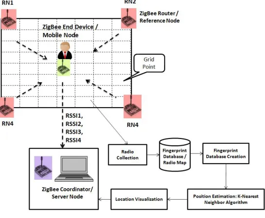
created during training phase. K-closest neighbor algorithm will be used to estimate the position of mobile node.Figure 1 shows the research methodology.
Figure 1: Research Methodology
II. IMPLEMENTATION METHOD Proposed Model:
In this section firstly we will understand the system architecture components and how roles and responsibilities are divided among these components. For embedded part, XBEE Maxstream modules and PIC16LF1939 microcontroller were used.
A] System Architecture Block Diagram:
Figure 1 represents the system architecture of proposed model. Main elements of the architecture are (a) Server, (b)Base Station/ Reference Node and (c)Client/Mobile Node.
(a) Server Node(SN): It is a laptop to which ZigBee network interface is provided. ZigBee coordinator device is connected
to the server for ZigBee network connectivity over UART. Application developed on server will be used to calibrate the floor and to monitor the location of mobile node from central location. Location fingerprinting algorithm will be implemented on this node. PC based application will be developed using VB.NET.
(b) Base Station(BS)/Reference Node (RN): This element is made up of Low cost 8 bit microcontroller
PIC16LF1939andZigBee Router Device. Microcontroller is interfaced to the ZigBee router device over UART. Application running on this microcontroller responds to the commands received from server over ZigBee network. It sends periodic frames to the client. More the no. of base stations, more accuracy could be achieved.
(c) Client/Mobile Node(MN): This element is made up of Low cost low power 8 bit microcontroller
Figure 2: System architecture diagram
B] 2-D Radio Location Fingerprinting
Objective of the proposed designis to detect 2D location of an Mobile Node (MN) within indoor environment. This implementation requires following two phases.
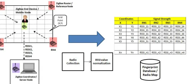
1] Training Phase or Calibration Phase:
In this phase, indoor area where position system is to be deployed is calibrated. Following steps are performed in this phase.
1.1. Divide premises area where location of an object is to be tracked into the grid. Note down the (Xi,Yi) coordinates of the grid the databases
1.2. At each grid point, measure the RSSI (Received Signal Strength Indicator) value of Reference Nodes (RN). 1.3. As RSSI at same location fluctuates with respect to time so take multiple samples for averaging the RSSI value. 1.4. Store the normalized RSSI values received from multiple reference nodes (RNs) into the fingerprint database with respect to grid point 2D coordinate.
Refer Figure 3to understand the dataflow of training phase and Figure 3 to understand its high level software implementation flow.
ISSN (Print) : 2320 – 3765 ISSN (Online): 2278 – 8875
I
nternational
J
ournal of
A
dvanced
R
esearch in
E
lectrical,
E
lectronics and
I
nstrumentation
E
ngineering
(An ISO 3297: 2007 Certified Organization)
Vol. 5, Issue 4, April 2016
Figure 4: High level software architecture for Training Phase
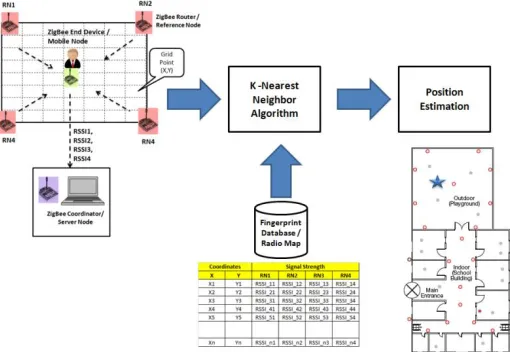
2] Location Estimation Phase:
In estimation phase, software running on remote laptop system will track the position of object by comparing the RSSI values received run time with those stored in the fingerprint database. GUI developed on the laptop will show the movement of mobile node across the floor. VB.NET software is used for the development of GUI for location monitoring system. Steps followed in location estimation phase are,
2.1. Get the RSSI values of reference nodes.
2.2. By using K- closest neighbor algorithm estimate the location of a mobile node within area. 2.3. Show the location of a mobile node on PC based monitoring software.
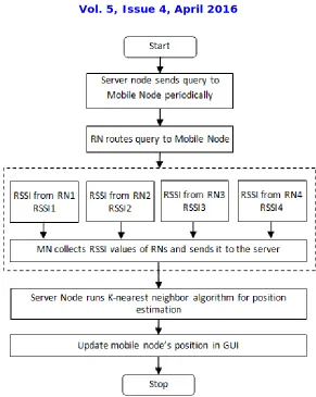
Refer Figure 5 to understand the dataflow of training phase and Figure 6 to understand its high level software implementation flow.
Figure 6: High level software architecture for estimation phase
The fingerprinting approach comprises of a setup or information gathering process in which, the sign qualities at each fixed sensor hub are measured and put away. Every record has the organization of {x, y, RSSi), RSSN}, where (x, y) is the grid position in the 2-D space, and RSSi is the gotten signal quality in dBm at the i-th fIxed hub. N, the aggregate number of fixed reference nodes. To lessen the impacts brought about by commotions and way misfortune, each RSSi is the normal of different estimations gathered over a period. The gathering of all estimations shapes a 2-D radio sign quality framework that comprises of the highlighted signal qualities, or fingerprint, at each tested position. Taking after the setup procedure, a portable sensor hub might be confined utilizing the sign qualities measured at each fixed hub. For confining a portable sensor hub, the calculation looks the 2-D radio grid gathered in the information accumulation stage, and discovers the fingerprint that best matches the sign qualities watched. That is, the versatile hub contrasts the watched signal vitality and the recorded, and picks the area (x, y) that minimizes the Euclidean separation as the area gauge. This strategy is additionally alluded to as closest neighbor technique. A slight variation of the procedure includes finding the k closest neighbors in sign space, and averaging their directions to get the area gauge. The accompanying clarifies the strides taken for the setup and area estimation forms utilizing fingerprinting strategy.
III. CONCLUSIONS
ISSN (Print) : 2320 – 3765 ISSN (Online): 2278 – 8875
I
nternational
J
ournal of
A
dvanced
R
esearch in
E
lectrical,
E
lectronics and
I
nstrumentation
E
ngineering
(An ISO 3297: 2007 Certified Organization)
Vol. 5, Issue 4, April 2016
system can be deployed in schools for keeping a track of children within school premises or to ping teacher remotely in case of emergency or in hospitals to ping a doctor in case of emergency.
REFERENCES
[I] I. F. Akyildiz, W. Su, Y. Sankarasubramaniam, and E. Cayirci, "Wirelesssensor networks: A survey," Computer Networks 1., 38(4), 393-422,2002.
[2] y. Li, Z. Wang, Y. Q. Song, "Wireless Sensor Network Design ForWildfire Monitoring," Proc. of The Sixth World Congress on IntelligentControl and Automation, WCICA, Vol. I, pp. 109-113, Dallan, 2006.
[3] M. K. Meyer, M. R. Brambley, "Pros & Cons of Wireless ", ASHRAEJournal, pp. 54-59, Nov 2002.
[4] 1. Yick, B. Mukherjee and D. Ghosal, "Wireless sensor network survey,"Computer Networks, 52(12), 2292-2330, 2008.
[5] D. Miorandi, E. Uhlemann, S. Vitturi, A. Willig, "Guest EditorialSpecial Section on Wireless Technologies in Factory and IndustrialAutomation-Part II," Industrial Informatics, IEEE Transactions on ,vol.3, no.3, pp.189-190, Aug. 2007.
[6] K. Muthukrishnan, M. Lijding, and P. Havinga, "Towards smartsurroundings: Enabling techniques and technologies for localization," inProc. of the Int. Workshop on location and context awareness(Loca2005),2005. [7] W.Y. Chung and C.S. Yang, "Dynamic VRML-Based Navigable 3DMap for Indoor Location-Aware Systems," Lecture Notes in ElectricalEngineering, 21, 269-284, 2008.
[8] AR. Jimenez, F. Seco, "Precise localisation of archaeological findingswith a new ultrasonic 3D positioning sensor," Sensors and Actuators A,123-124,224-233,2005.