1
Welcome
VAConnect is used to design structural steel base plates and their anchorage, shear tab connections (also known as single-plate connections), and welded flange plate moment connections. The base plate design is base on the AISC Design Guide 1 and the ACI 318 design specifications while the shear and moment connections are based on the 15th edition of the AISC Steel Construction Manual. In addition to being run as a standalone application, VAConnect can be launched from within VisualAnalysis, VisualFoundation, and ConcreteBending (see the Integration with IES Programs page for details).
Getting Started
How-To Tutorial Videos
Use File | Open Example to see sample projects. Feature List
Program Layout
Upgrade Guide (what's new)
FAQ Answers at iesweb.com for business, licensing, installation issues. Downloadable PDF Help file.
Help Notation
Menu items appear like this: File | New.
Keystrokes or mouse commands appear like this: Shift+Click.
Disclaimer
VAConnect is a proprietary computer program of Integrated Engineering Software (IES, Inc.) of Bozeman, MT. This product is intended for use by licensed, practicing engineers who are educated in structural engineering, students in this field, and related professionals (e.g. Architects, Building Inspectors, Mechanical Engineers, etc.). Although every effort has been made to ensure the accuracy of this program and its documentation, IES, Inc. does not accept responsibility for any mistake, error, or misrepresentation in, or as a result of, the usage of this program and its documentation. (Though we will make every effort to ensure that problems that we can correct are dealt with promptly.) The results obtained from the use of this program should not be substituted for sound engineering judgment.
License and Copy Restrictions
By installing VAConnect on your computer, you become a registered user of the software. The VAConnect program is the copyrighted property of IES, Inc. and is provided for the exclusive use of each licensee. You may copy the program for backup purposes and you may install it on any computer allowed in the license agreement. Distributing the program to coworkers, friends, or duplicating it for other distribution violates the copyright laws of the United States. Future enhancements and technical support depend on your cooperation in this regard. Additional licenses and/or copies of VAConnect may be purchased directly from IES, Inc.
IES, Inc.
Integrated Engineering Software, Inc. 519 E. Babcock St.
Bozeman, MT 59718
2
Key Features
Modeling
VAConnect performs design checks for the following connections: Steel Base Plates Anchored to Concrete
Shear Tabs (Single-Plate Connections) Welded Flange Plate Moment Connections
VAConnect works as stand-alone products for quick connection checks or design
VAConnect can be launched from within VisualAnalysis, VisualFoundation, and ConcreteBending for importing: Member shape geometry
Names and design criteria settings
Design Forces from many LRFD load combinations and load sets
Loading
Apply loads in multiple service load cases (e.g. Dead, Live, Seismic, etc.) Automatic building code load combinations are available
Includes IBC, ASCE, and NBC Load Combination Create custom load combinations in any project Create patterned load cases
Create Load Sets so one connection can be designed for use in multiple locations
Reporting
Report includes graphics of the model
Reports provide detailed hand style calculations
Customize reports to include specific detailed calculations or tables Print Preview mode while working with reports
Print to any printer including PDF Export reports to .doc or .xlsx
General
Dynamic graphical display of the connection to visually validate inputs Standard Windows interface for easy navigation
Unlimited Undo & Redo commands
Work in any unit system, perform math on input, and use custom unit 'styles' Program is self-documenting with tooltips on commands and input parameters Numerous preference settings for better defaults
Free Training Videos provided for learning efficiency Free technical support email with quick responses
Be a Squeaky Wheel
If you need a new feature, please let us know. We are always looking for ways to improve products in ways that you desire. See Support Resources.
3
Program Layout
Explore
The best way to learn VAConnect is to explore the program and try things yourself. Get to know what is available under each button or menu. Also, check out the tutorial videos.
Screen Layout
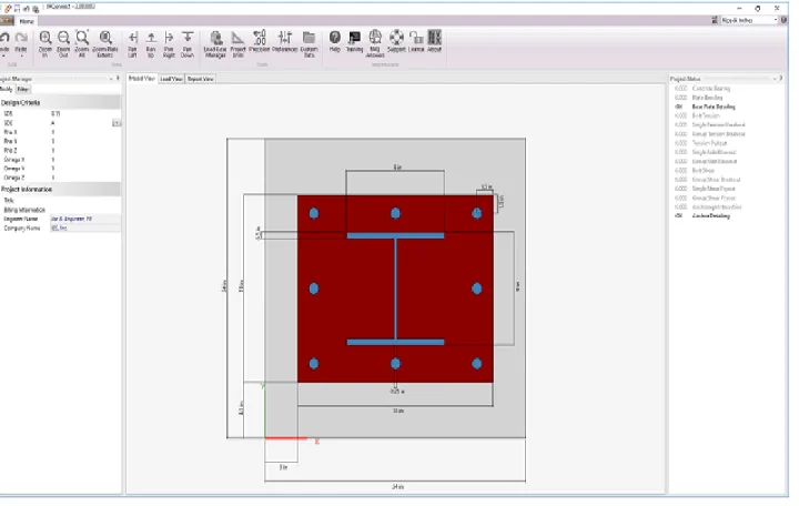
The image below introduces the program terminology used in this help file and the training videos. Panels may be resized by dragging their dividers or repositioned by dragging their title bars or right-clicking on the title. Use the "pushpin" icon to collapse panels temporarily to gain more space for working. Hold your mouse over the screen image below for information about each area of the program.
Main Menu / Toolbar
Each command on the menu or toolbar is accessed with a left mouse click. Helpful descriptions or tool-tips are available by hovering the mouse over the command.
Project Manager
Modify Tab: Use this tab to change properties of selected objects, apply loads, or customize reports. Filter Tab: Use this tab to control what is shown or hidden in the active view.
Graphic Views
These views provide a way to view the model, the applied loads, or the reports. Each tab displays different options and will provide different information in the Project Manager. The Model View graphically displays the geometry of the connection. Click on the different components of the model to adjust the geometry and/or material properties for that
component. The Load View graphically displays the loads on the connection. Use this view to add service level loads, create load sets, and define the load combinations. The Report View displays the report for the connection which can be modified to be as concise or as comprehensive as needed.
Project Status
This panel provides a quick summary on which design limit states are passing or failing. Click on the various items to see the calculates for the design checks.
Units & Precision
VAConnect can display physical quantities in a variety of unit-systems, including custom unit styles. Select the unit system to use for all the displayed values and adjust the precision (number of decimal places) using the controls in the upper right corner.
Data Entry: Physical Quantities
Values may be input in any unit: enter any number or math expression followed by a known unit abbreviation. Length units may be entered in the "ft-in-16ths" notation. Entered values are converted and then redisplayed in the current 'display' units.
Mouse and Keyboard Commands
Selection:
Click to select
Click in the 'whitespace' of a view to unselect everything
Zoom:
Use the mouse wheel, position the mouse over the point from which to zoom in to or out Ctrl+ (plus) and Ctrl- (minus) keys.
Ctrl+Home for zoom all/extents
Pan:
Hold the mouse wheel down (like a button, not scrolling it) and drag the mouse. Shift+Arrow keys will also pan.
Middle-Mouse "Button" in Windows
Depending on your system, you may need to go into Control Panel, Hardware, Mouse, and set the wheel button to behave like a "middle button click". Some mouse utility programs may override that setting or it may not be set up on some versions of Windows.
4
Release History
Version 4.0 released May 2019 Version 3.0 released November 2017 Version 2.0 released January 2014 Version 1.0 released January 2013Version 4.0 Features
Merged Base Plate and Shear Tab into single application Significant changes and improvements to user interface Added Welded Flange Plate Moment Connection Shear Tab Features:
Improved shear, tension, and flexure interactions (per AISC Design Examples Version 15.0) Improved biaxial block shear interaction (per AISC Design Examples Version 15.0)
Updated base metal limit state to account for eccentric loading Base Plate & Anchorage Features:
Added Case 3 for concrete breakout (per ACI 318-14 Fig. R17.5.2.1b) Upgraded to AISC 360-16 and the 15th edition of the AISC Steel Construction Manual Updated dynamic project status will more visible limit states
New web-based Help file that is up to date with the design specifications
Version 3.0 Features
ACI 318-14 concrete specification ASCE 7-16 load combination support
Threaded rod anchor sizes from 2-4 inches are available One inch HAS (headed studs) are available
Load case manager improvements and updates Added material database
Database for steel shapes may be used Preference settings (to speed up new projects) Many visual/user-interface improvements Improved validation and testing
Crash prevention improvements
Version 2.0 Features
New licensing system Upgraded to work with VA11
Version 1.0 Features
Steel Base Plate (with anchorage checks per ACI Appendix D) Steel Shear Tab (bolted to beam, welded to column or girder) Steel checks per AISC 360-10 (13th Edition)
5
Integration with IES Programs
VAConnect may be run as a standalone program or launched from within VisualAnalysis, VisualFoundation, or
ConcreteBending. Launching from these IES products allows loading demands and available connection information to be exported from the model to VAConnect. The following table shows the connection types that are supported by the various IES programs.
IES
Program
Plate
Base
Shear
Tab
Welded
Flange
Plate
VisualAnalysis Yes Yes Yes VisualFoundation Yes No No ConcreteBending Yes No NoIntegration with VisualAnalysis
IES VisualAnalysis is a 3D integrated analysis and design tool used to model a variety of structures using an assortment of materials. VisualAnalysis determines the flow of forces through a structure for each load combination and can perform design checks for the structural members based on a number of different design specifications. Using the steps below, VisualAnalysis can directly export member and load data to VAConnect to expedite the connection design and eliminate the bookkeeping involved with moving information between the computer programs.
1. Create a structural model in VisualAnalys, apply load, and select the appropriate load combinations. 2. Switch to the Results View to validate/review the analysis results.
3. Switch to the Design View tab in the graphics view and ensure that the Steel Connections filter is set to "Shown" in the Project Manager | Design Filter tab to display the connections graphically.
4. Create/Modify the desired connection groups using the buttons in the connections section of the Design Ribbon.
5. Select a connection and click the Design in VAConnect button to launch VAConnect and automatically import the member, load combination, and load set data for the connection.
6. Modify the connection in VAConnect until all of the design checks pass.
7. Save the VAConnect project file if desired to open it later in the stand-alone mode.
8. Exit VAConnect, the design report is automatically sent back to VisualAnalysis and the connection Design Status is change from 'Not Performed' to either 'Checks Passed' or 'Checks Failed'.
Note: the import from VisualAnalysis feature is unidirectional as VisualAnalysis does not store any input data or changes made to connection project files. Editing the model or the loads in VisualAnalysis will reset the Design Status of the connections to 'Not Performed' and they will need to be redesigned.
Integration with VisualFoundation
IES VisualFoundation is used to analyze and design a wide variety of concrete foundation systems, including complex mat footings, pile caps, grade beam systems, and combined footings. VisualFoundation can export pier-loads to VAConnect for a steel-column base plate design. After defining all of the loads, select the pier(s) in the Model & Loads view, and click the Export to VAConnect button in the Foundation Ribbon.
Integration with ConcreteBending
IES ConcreteBending is used to analyze and design a wide variety of concrete elements in flexure, including elevated slabs, beams, tank walls, and foundation walls. ConcreteBending can export point loads to VAConnect for a steel-column base plate design. After defining all of the loads, select the load point(s) in the Model & Loads view, and click
6
Loads
Load Cases and Combination Types
The load case manager is used to view and manage all load cases and load combinations in the project. Under the Service Cases tab, new service cases can be created and existing service cases can be modified or delete. Under the Load Combinations tab, the load combinations from several different building codes can be added or custom Factored combinations can be created.
Case Type
Description
Service Case A container for holding physical loads grouped by load source. These load cases are not used directly for the design checks.
Building Code Combination Automatic load combinations are generated based on defined building code equations. While building code combinations cannot be modified, the combinations from various codes can be included or excluded from the analysis. Also, any automatic load combination can be converted to a custom Factored Combination. Factored Combination Custom combinations of service cases with load factors that can be used for design
checks.
Service Cases & Load Sources
Loads on a structure can come from a variety of sources such as the self-weight of the structure (Dead Load), external loads applied to the structure (Live Load, Snow Load, Wind Load, etc.), loads from inertia forces due to dynamic motion (Seismic Loads), and loads that are self-straining (Thermal Loads, Creep Loads, etc.). A variety of load sources are available in VAConnect (see the table below) which are based on the ASCE 7 and IBC design specifications. Service loads are the actual imparted loads on the structure to be used in the Load Combinations for the design checks. VAConnect automatically generates the service cases in the table below based on the various load sources. While load sources cannot be modified in VAConnect, custom Service Load Cases can be manually added in the Service Cases tab of the Load Case Manager. For example, a "Creep" Service Load Case could be added based on the Self Straining Load Source. All loads are added at the service load level in VAConnect.
Load
Source
Service Load Case
Explanation
Dead D The self-weight of the structure and permanent fixtures on or in the structure.
Dead (Ice) Di The weight of ice on the structure.
Live L Loads due to moveable equipment or occupancy. Caution: Live loads are reduced by 50% in some IBC load combinations, use Lpa source for loads > 100 psf.
Live (Public Assembly)
Lpa(>100psf) Garage loads, Public Assembly areas, or loads greater than 100psf. They have also been called "Exception" loads, because they appear in a separate clause in some building codes.
Roof Live Lr Roof live loads.
Rain R Rain load on an undeflected roof (excludes contributions from ponding).
Snow S Snow loads.
Seismic Loads (directional)
E+X, E-X, E+Y,E-Y,
E+Z, E-Z Earthquake or Seismic loads. E+X is for seismic loads in the positiveglobal X-direction, E-X is in for the negative global X-direction, and similarly for the Y-direction and Z-direction.
Earth
Pressure H Load due to lateral earth pressure, ground water pressure, or pressureof bulk materials Fluids F Fluid load such as water in a storage tank.
Flood Fa Loads that result from water exceeding the local ground elevation. Flood load come from hydrostatic and hydrodynamic pressures such as water flowing over a bridge or waves passing through a building. Self
Straining T Loads from thermal expansion, creep, support settlement, etc. Wind
loads (directional)
W+X, W-X, W+Y, W-Y,
W+Z, W-Z Wind pressure loads. W+X is for wind loads in the positive global X-direction, W-X is for wind loads in the negative global X-direction and similarly for the Y-direction and Z-direction. Skewed wind load directions are also available (W+X+Y, W+X-Y, W-X+Y, etc.). Wind on Ice Wi+X, Wi-X, Wi+Y, Wi-Y,
Wi+Z, Wi-Z, Wind on Ice. The presence of ice can increase the surface-area ofmembers and therefore the wind forces. Other loads Other User-defined source available for special loads that need to be
factored independently of other sources. These loads are not used in Building Code Combinations but can be used in Custom Factored Combinations.
Building Code Combinations
Building code combinations from a variety of building codes are built-in to VAConnect. The codes that are selected in the Load Case Manager are automatically maintained as loads are added or removed to the service cases. The building code combinations implemented in VAConnect do not necessarily represent all possible load combinations or variations present in a particular building code (for example, in the implementation of ASCE 7-10 load combinations, the major equations are implemented, but exceptions clauses of section 2.4 dealing with H, F, Fa are not implemented directly). When one of the building code combinations is selected, VAConnect will use the current service load cases and
generate the necessary combinations prescribed for that code. Note that any custom equation or factored combinations that are created manually will remain unaffected. When VAConnect generates building code combinations, it will generate combinations including the effects of wind and seismic in various directions, including (+/-X, +/-Y, +/-Z). Only load cases that actually contain loads are included in the combinations. The Load Case Manager displays the 'effective' combination of the equation which may be different than the equation in the building code.
Custom Load Combinations
Use the Create Factored Combination button located in the Load Case Manager to create any custom combination needed. Custom factored load combinations can be imported from the clipboard using the Import From Clipboard button in the Load Combinations tab in the Load Case Manager. Text must be tab delimited and copied to the clipboard in the following format:
{ComboName} {Factor} {ServiceCaseName} {Factor} {ServiceCaseName2} … For example:
ComboName 1.2 D 1.6 L 0.5 Lr MyCombo 0.9 D 1.3 W
Patterned Load Cases
Service cases may be given a pattern ID number allowing for various loading patterns to be modeled (such as loads on
Load
the odd/even spans). Each patterned service load case is combined independently in building code load combinations from other patterned load cases. For example, when dead load is applied and odd-span live loads are in a "Pattern 1" service case and even-span live loads are in a "Pattern 2" service case, the building code combination will generate the following combinations:
1.2D + 1.6L(1) (#1) 1.2D + 1.6L(2) (#2)
Any loads in an non-patterned load case (i.e. the dead loads for the example case above) are included in all of the load combinations. All of the built-in service cases have a default load patterns of 0 that cannot be changed. Therefore, new service cases must be created to define load patterns.
Load Sets
It is common for the same connection to be used at multiple locations throughout a structure and experience numerous loading conditions. The Load Sets feature in VAConnect allows a single connection to be designed with multiple sets of loads. For example, consider a structure with two W16x36 beams that use identical shear tab connections. The beams carry service level loads that produce the service level shear forces in the connection shown in the table below.
Service
Load
Case
Load Set 1 =
Beam 1 Shear
Force (kips)
Load Set 2 =
Beam 2 Shear
Force (kips)
Dead (D) 10 9 Live (L) 20 24 Snow (S) 20 16It is not immediately apparent which set of loads (the shear on Beam 1 or Beam 2) will control the design of the connection. Based on ASCE 7, one of the following load combinations will control the design of the connection. The table below shows the six load combinations (three from each load set) that are used to design the connection. In VAConnect, the connection is designed for all six load combinations and can therefore be used for both beams. 1) 1.4D
2) 1.2D + 1.6L + 0.5S 3) 1.2D + 0.5L + 1.6S
Load
Set
Load Combination
Connection
Design
Loads (kips)
Beam 1 1.4D 14.0 Beam 1 1.2D + 1.6L + 0.5S 54.0 Beam 1 1.2D + 0.5L + 1.6S 54.0 Beam 2 1.4D 12.6 Beam 2 1.2D + 1.6L + 0.5S 57.2 Beam 2 1.2D + 0.5L + 1.6S 48.87
Base Plate Design
The base plate connection consists of a steel plate that is welded to the base of a column and anchored to a concrete slab or pedestal via threaded rods, hooked bolts, headed bolts, or headed studs. The connection resists the reactions from the column including the axial force, shear forces, and moments.
Design Considerations
Steel base plates and anchorage subjected to applied axial forces and overturning moments are analyzed according to AISC Design Guide 1 (DG1)
Base plate design checks for flexure are performed per AISC 360-16 (15th Edition) Concrete bearing design checks are performed per ACI 318-14
Anchorage design checks for shear and tensions demands are performed per ACI 318-14 Chapter 17 Anchorage breakout areas for both shear and tension can be graphically displayed
Anchorage breakout checks can be suppressed when reinforcing is provided to prevent breakout
Limit States
VAConnect checks the following limit states for Base Plates (refer to the program’s detailed reports for code references):
Concrete bearing Steel plate bending Base plate detailing
Bolt spacing
Bolt minimum edge distances for the steel plate Bolt tension
Single anchor tension breakout Anchor group tension breakout Tension pullout
Single anchor side blowout Anchor group side blowout Bolt shear
Anchor group shear breakout (cases 1, 2 & 3) Single anchor shear pryout
Anchor group shear pryout
Anchorage tension and shear interaction Anchorage detailing
Anchor spacing Anchor side cover
Limitations
Permitted shapes: I-Beams, HSS (rectangular tubes), Pipes, and Rectangular or Round Columns Base plate is assumed to be perpendicular to the member's local axis
Limited to a single member framing into the plate (i.e. braces may connect to the base plate) All of the limitations of DG1 apply to the base plate program, notably:
DG1 does not support biaxial bending in the plate
DG1 does not support the case of an applied axial tension and applied moment Only one row of anchors is allowed around the four sides of the base plate
DG1 simplifies the base plate analysis into essentially a one dimensional problem (engineering judgment is required to determine when this simplifying assumption is appropriate)
Please refer to DG1 for further information The column-to-base-plate weld is not checked
Only bending design checks are made on the plate (bolt bearing, block shear, and other steel connection checks are not considered)
The anchorage design checks do not support post-installed anchors
The overstrength option (17.2.3.4.3d) is used for seismic design for both shear and tension. Also, the tension capacity is reduced per 17.2.3.4.4. Therefore, the user must to define omega in the project criteria to
considering seismic effects.
The provisions of ACI 318 Section 17.5.2.1 (c) and (d), concerning shear parallel to an edge and shear at a corner, are not checked (these checks can be manually performed, by applying the correct load towards the edge)
A torsional column reactions are not considered in the analysis or design Biaxial shear anchorage interaction is not supported
Shear Breakout Groups and Load Distribution
Various load distributions must be considered when designing anchors for shear demands. This process is described by Figure R17.5.2.1b of ACI 318 chapter 17. The figure describes three cases that must be considered when designing for shear breakout. The logic behind the commentary cases, which involves only two anchors, leads to many possible breakout cases when the group has multiple anchors. VAConnect's anchorage design checks take the following approach:
A breakout group is considered for each anchor in the connection. The shear force carried by each group is taken as the total shear demand times the ratio of the anchors in the breakout group to the total number of anchors in the connection (see Figure 1 below). The shear limit states of bolt shear and pryout are checked for each breakout group. VAConnect can graphically display the breakout group for each anchor.
If the anchors are welded to the steel plate (as specified by the user), only the breakout group starting from the back row of anchors (Case 2) is considered as discussed in ACI 318 Section 17.5.2.1 (see Figure 2).
Figure 3, then the failure surfaces may merge and Case 3 is conservatively used for the strength of the breakout group (see ACI 318 Section 17.5.2.1). It should be noted that Case 3 is also applicable if the base plate holes are such that front row of anchors take the majority of the load before the rest of the anchors are engaged (see Example 8 of ACI 355.3R-11 page 76 for further discussion of when this more severe load distribution may exist). VAConnect, however, does not considered Case 3 based on the bolt hole condition.
Bolt Shear and Load Distribution
When the anchors near the free edge start to form a failure cone due to concrete breakout the load will redistribute to the stiffer rear anchors as explained in ACI 318-14 R17.5.2.1. Therefore, VAConnect only uses the anchors farthest from the edge (on the perimeter of the breakout group) for the bolt shear limit state (see Example 10 of ACI 355.3R-11 particularly page 92). Figure 4 shows the demand and the number of bolts that resist shear for the breakout group associated with each anchor (as shown in Figure 1). The bolt shear unity value (Vu/φVn) is conservatively taken as the maximum unity value of all the cases for bolt shear regardless of which breakout case controls.
Anchorage Interaction
The anchorage design checks consider the interaction of tension and shear forces per ACI 318 Section 17.6. The design checks, however, do not consider the interaction of biaxial shear forces in two perpendicular directions. In the case of a connection subjected to shear forces in the X and Y directions (Vx and Vy) and a tension force (T), the interaction check will consider Vx combined with T and Vy combined with T, separately. The combination of Vx, Vy, and T is not
considered by the program because there is no guidance provided by the ACI 318 specification. Therefore, this particular design check is left to the discretion of the user.
8
Shear Tab Design
Shear Tab connections (also know as Single-Plate connections) are used to connect steel beams to column or girders. In addition to resisting shear force, these connections can resist axial load.
Design Considerations
Shear Tab connections are checked per the AISC Steel Construction Manual Part 10 (15th Edition) and AISC 360-16 design specifications. The shear tab connections in VAConnect are always designed using the extended procedure described in AISC Part 10 since this procedure can check a wider variety of connections than the AISC design tables. VAConnect uses the Instantaneous Center of Rotation method for eccentrically loaded welds groups to check the capacity of the welds and base metal. The Instantaneous Center of Rotation method is also used for eccentrically loaded bolt groups to check the bolt shear capacity and the bolt bearing capacity on the shear tab and web of the beam. The “C” coefficients for eccentrically loaded bolt groups are included in the detailed reports.
Combined Axial Force and Eccentric Shear Force
VAConnect allows shear tabs to be designed for combined eccentric shear force (force in-plane and parallel to the bolt line) and axial force (force in-plane and perpendicular to the bolt line). While the 15th edition of the AISC Steel Construction Manual does not explicitly address this combined force condition, Example II.A-19B of the AISC Design Examples Version 15.0 provides a detailed example of an extended shear tab connection subject to axial and shear loading. While previous version of VAConnect relied on engineering judgment to account for the axial force,
VAConnect has been revised to closely follow the aforementioned AISC design example. Specifically, the interaction of the shear, axial, and flexural loads are considered for both the yield/buckling and the rupture cases and the interaction for biaxial block shear are accounted for according to the example. The program’s detailed reports clearly document how the various limit states have been checked.
Limit States
VAConnect checks the following limit states for Shear Tabs (refer to the program’s detailed reports for specific code references):
Bolt Group Shear
Bolt Group Bearing - Shear Tab & Beam Web Fillet Weld - Shear Tab to Support
Base Metal - Shear Tab & Support
Block Shear - Beam Web (Axial Load Only)
Block Shear - Shear Tab (Shear & Axial Interaction) Shear Yield - Shear Tab
Tension Yield - Shear Tab
Compression Buckling - Shear Tab Flexural Yielding/Buckling - Shear Tab Yielding/Buckling Interaction - Shear Tab Shear Rupture - Shear Tab
Tension Rupture - Shear Tab Flexural Rupture - Shear Tab Rupture Interaction - Shear Tab Shear Tab Detailing
Shear tab maximum plate height
Maximum plate thickness (plate moment capacity vs. bolt group moment capacity) Fillet weld maximum and minimum size
Welds are adequate to developed Shear Tab strength Maximum and minimum bolt spacing
Maximum and minimum bolt edge distances
Limitations
Permitted beam shapes: I-Beams and Channels
Permitted supporting member shapes: I-Beams, Channels, HSS, Pipe, Rectangle, or Round. The support member is only limited when importing from VisualAnalysis.
The support element is only considered as far as it affects the weld design (e.g. base metal check, minimum and maximum fillet weld sizes)
Weld base metal checks assume that there is not a connection on the opposite side of the support Beam is nearly perpendicular to column or girder
A single member framing into a support column or girder Only a single vertical column of bolts is allowed
Beam shear yield, shear rupture, tension yield are not checked Coped beams are not supported
Only standard bolt holes are supported
Only forces in the plane of the connection (shear and axial) can be checked
When an unrecognized beam is imported from VisualAnalysis, the beam’s T dimension is assumed to be the depth minus twice the flange thickness (i.e. the fillets are neglected)
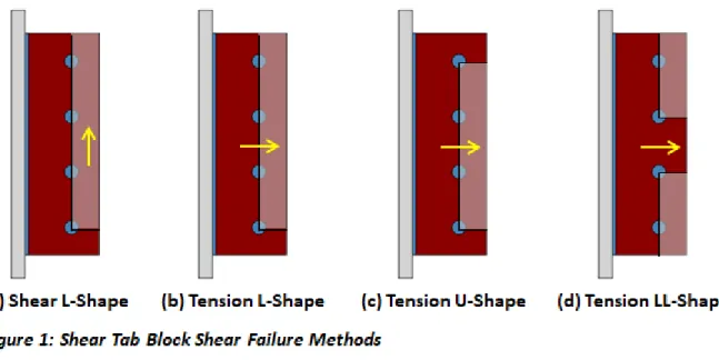
Block Shear
Figure 1 shows the possible block shear failure methods that VAConnect checks for the shear tab. In addition to checking each case (a through d) independently, the interaction for block shear failure from combined shear and tension is considered. While combined block shear only needs to be checked for case a and case b in Figure 1, VAConnect conservatively uses the lowest capacity from case b through case d for tension to combine with case a for shear. Only the Tension U-Shape case is check for block shear of the beam's web since coped beams are not supported by VAConnect.
9
Welded Flange Plate Design
A Welded Flange Plate connection consists of two steel plates that are welded to both the support and the flanges of the beam to resist moment. VAConnect assumes that the Welded Flange Plate connections possess sufficient rigidity to maintain the angles between the connected members and behave as fully restrained moment connections as discussed in the AISC Steel Construction Manual Part 12. While various simple shear connections can be used in conjunction with welded flange plates, VAConnect uses a shear tab to resist the applied shear loads.
Design Considerations
Welded Flange Plate Tab connections are checked per the and AISC 360-16 design specifications. VAConnect allows the flange plates to be connected to the support with either a double sided fillet weld or a complete-joint-penetration groove weld. The capacity of the complete-joint-penetration groove welds are not checked since the strength of the joint is controlled by the base metal according to AISC 360-16 Table J2.5. The length of the weld at the support can be manually set to a value less than the width of the flange plate which is needed for cases when the flange plate is wider than the support. Fillet weld are used to connect the flange plates to the flanges of the beam. The end weld (i.e. the weld along the back edge of the flange plate perpendicular to the beam's span) can be enabled or disabled. When the end weld is disabled, the weld group is two parallel lines and when enabled the weld group is in a U-shape. To avoid overhead welding in the field, the top flange plate is typically narrower than the top flange (with an end weld) while the bottom flange plate is typically wider than the bottom flange without an end weld. To allow enough room for placement of the fillet welds, VAConnect requires the difference between the width of the flange plate and the width of the beam's flange to be greater than or equal to two times the size of the weld.
Load Distribution - Moment, Axial, & Shear
Shear is transferred from the web of the beam to the support through the shear tab connection. Since the angle between the beam and the support in a fully restrained moment connection remains unchanged under loading, eccentricity in the shear tab is neglected entirely.3 To satisfy equilibrium, the moment from the eccentric shear force (eccentricity · Fv) is added to the moment applied to the connection (Mz). The axial force is assumed to be distributed uniformly to the flanges of the beams (the shear tab connection is therefore assumed to have negligible axial stiffness compared to the flange plate connections). The moment at the connection is resolved into an effective
tension-compression couple acting as axial forces at the beam flanges. Finally, the forces in the flanges plates can be calculated as R = (Mz + eccentricity · Fv) / (d + 0.5·(ttp + tbp)) ± Fa/2.
Limit States
VAConnect checks the following limit states for Welded Flange Plates (refer to the program’s detailed reports for specific code references):
Bolt Group Shear
Bolt Group Bearing - Shear Tab & Beam Web Fillet Weld - Shear Tab to Support
Base Metal - Shear Tab & Support Block Shear - Shear Tab (Shear Only) Shear Yield - Shear Tab
Shear Rupture - Shear Tab
Tension Yield - Top & Bottom Plate Tension Rupture - Top & Bottom Plate Compression Buckling - Top & Bottom Plate Block Shear - Top & Bottom Plate to Flange Fillet Weld - Top & Bottom Plate to Flange Base Metal - Top & Bottom Plate & Flange Weld - Top & Bottom Plate to Support
Base Metal - Top & Bottom Plate to Support Welded Flange Plate Detailing
Shear tab maximum plate height
Shear tab maximum plate thickness (plate moment capacity vs. bolt group moment capacity) Shear tab fillet weld maximum and minimum size
Shear tab number of fillet weld lines
Welds are adequate to developed Shear Tab strength Maximum and minimum bolt spacing
Maximum and minimum bolt edge distances
Flange plate fillet weld maximum and minimum size Flange plate's width-to-thickness ratio is nonslender
Limitations
Permitted beam shapes: I-Beams and Channels
Permitted supporting member shapes: I-Beams, Channels, HSS, Pipe, Rectangle, or Round. The support member is only limited when importing from VisualAnalysis.
The support element is only considered as far as it affects the weld design (e.g. base metal check, minimum and maximum fillet weld sizes)
Weld base metal checks assume that there is not a connection on the opposite side of the support Beam is nearly perpendicular to column or girder
A single member framing into a support column or girder Only a single vertical column of bolts is allowed for the shear tab Web and flange yield and rupture are not supported
Only standard bolt holes are supported
Only forces in the plane of the connection (shear, axial, and moment) can be checked
When an unrecognized beam is imported from VisualAnalysis, the beam’s T dimension is assumed to be the depth minus twice the flange thickness (i.e. the fillets are neglected)
Only fillet welds and complete-joint-penetration groove weld are allowed at the support (partial-joint-penetration groove weld are not supported)
The flange plates are assumed to resist the moment and axial load and no shear
Block Shear
The block shear failure method at the plate-to-flange connection depends on the both the end weld condition and the relative width of the plate to the flange. VAConnect automatically checks the all of the applicable block shear cases as outlined in Figures 1 through 4 below.
10
Reporting
In VAConnect, reports are easily created to document the connection design. Switch to the Report View tab and select from the available detailed reports or tables in the Project Manager | Modify tab to include in the report. The Design Summary report displays an image of the model with some input data and each limit state conveniently summarized in one table. The Detailed (hand calculation style) reports show intermediate calculations for every limit state. The Table reports summarize each limit state with a row for each design load. Load keys are used to identify each design load and its corresponding result. Load keys uniquely identify the paired load set and load combination that created the ultimate strength design load.
11
Support Resources
Did you Search this Help File?
Be sure you make use of the help and support built into the software, as described in the Program Layout section of the User's Guide. This document may be searched, and you should try various search terms, sometimes less is more when searching -- use just the unique word or words. There is also a logical Table of Contents available.
Do Not Contact Support For
Licensing or Sales: use www.iesweb.com or [email protected].
Questions about how to model a particular structure. Such questions are your responsibility as an engineer. IES cannot validate your model or your results. If they "seem" incorrect, please figure out WHY they are incorrect. If you can document a defect, we will be happy to investigate deeper and fix things as necessary. Questions about engineering theory. IES is not in the business of educating engineers. There are
design guides referenced in this help file and we can provide more guidance as to where to look if you cannot find one.
Technical Support
Email Support: [email protected] (Replies are usually within 2 business hours, if you don't hear anything within a day, assume it got spam filtered or lost and follow-up. For best results, be sure to ask a question, indicate exactly which IES product & version you are using, include as much detail as is practical or relevant, including attaching a project file.
Telephone Support: No, sorry. We have found this to be too inefficient for everybody. With email you can attach a screen shot, a project file, and we can better direct your question to the IES expert for that product or area. Phone 'tag' takes longer than you think.
Business Questions: For any licensing or sales-related questions or issues: [email protected]. Free Training Videos: Training videos can be accessed here.
12
References
1. Fisher, James M., Ph.D., P.E. and Kloiber, Lawrence A., P.E. Design Guide 1: Base Plate and Anchor Rod Design. Second Edition. Chicago, IL: American Institute of Steel Construction, 2006. Print
2. ACI Committee 318. Building Code Requirements for Structural Concrete (ACI 318-14) and Commentary. Farmington Hills, MI: American Concrete Institute, 2014. Print
3. AISC Committee on Specifications. Steel Construction Manual. Fifteenth Edition. Chicago, IL: American Institute of Steel Construction, 2017. Print
4. AISC Committee on Specifications. Specification for Structural Steel Building (AISC 360-16). Chicago, IL: American Institute of Steel Construction, 2016. Print
5. AISC Committee on Specifications. Design Examples. Version 15.0. Chicago, IL: American Institute of Steel Construction, 2017. Print
13
Training Videos
Video List
You will find the following videos below, showcasing several features available in VAConnect. Introduction
Base Plate Design Anchorage Design Shear Tab Design
Welded Flange Plate Design Integration with IES Products
Introduction
(BACK TO TOP)
VAConnect is a powerful design tool that allows you to quickly design shear tab connections, welded flange plate moment connections, and steel base plate connection that are anchored to concrete members. VAConnect checks the various strength limit states while also ensuring that the connection is correctly detailed.
Base Plate Design
(BACK TO TOP)
Base plates in VAConnect are designed according to the AISC Design Guide 1 to resist shear, moment, and axial load. The program specifically checks the limit states of concrete bearing, steel plate bending, and base plate detailing.
Anchorage Design
(BACK TO TOP)
Base plate anchorage in VAConnect is design according to the ACI 318 specification (specifically, Chapter 17). Numerous limit states are checked to satisfy the ACI design specification. Also, anchorage in VAConnect can be designed to resist seismic load according to the ACI seismic provisions.
Shear Tab Design
(BACK TO TOP)
Shear tab connections (which are also known as a single plate connections) are designed in VAConnect using the extended configuration outlined in Part 10 of the AISC Steel Construction Manual. Shear tabs can be designed to resist both the eccentric shear force and axial load and VAConnect specifically designs the connection for the interaction of these loads.
Welded Flange Plate Design
(BACK TO TOP)
Fully restrained welded flange plate moment connections are designed in VAConnect according to the AISC Steel Construction Manual. VAConnect assumes that the flange plates resist all the moment and axial load while the shear tab carries all the shear force. Therefore, the shear tab is designed to resist the shear directly without eccentricity.
Integration with IES Products
(BACK TO TOP)
In addition to being run as a standalone application, VAConnect can be launched from within other IES programs such as VisualAnalysis, VisualFoundation, and ConcreteBending. Launching from these programs conveniently allows the loading demands and available connection information to be exported from the model to VAConnect.