EPICARDIAL WIRELESS PACEMAKER FOR IMPROVED LEFT VENTRICULAR RESYNCHRONIZATION (CONCEPTUAL DESIGN)
A Thesis presented to
the Faculty of California Polytechnic State University, San Luis Obispo
In Partial Fulfillment
of the Requirements for the Degree
Master of Science in Engineering with Specialization in Biomedical Engineering by
COMMITTEE MEMBERSHIP
TITLE: Epicardial Wireless Pacemaker for Improved Left Ventricular Resynchronization (Conceptual Design)
AUTHOR: Rodney Hawkins
DATE SUBMITTED: December 2010
COMMITTEE CHAIR: Dr. Lanny Griffin, BMED Department Chair
COMMITTEE MEMBER: Dr. Dan Walsh, BMED Professor
Abstract
Epicardial Wireless Pacemaker for Improved Left Ventricular Resynchronization (Conceptual Design)
Rodney Hawkins
The human body is a well tuned mechanism where systems work in synergy to provide a healthy quality of life. The human circulatory system transports oxygenated blood from the heart to the rest of the body delivering the proper nutrients for cells to function. When the heart malfunctions, serious complications can arise leading to sudden cardiac arrest. Congestive heart failure (CHF) is one heart disease that affects the synchrony of the heart’s ventricles.
Cardiac resynchronization therapy (CRT) has been widely accepted as a treatment for CHF. Similar to traditional dual chamber pacing techniques, CRT adds a pacing lead to stimulate the left ventricle. Left ventricular leads are implanted via the coronary sinus which provides the easiest surgical access to the left ventricle. Another option for LV pacing is by using an epicardial lead. This option has proven to be safe and effective but requires major surgery. An epicardial lead is usually implanted by performing a thoracotomy. Many studies have been done to show the benefits of bi-ventricular pacing, therefore
traditional CRT device electrically coupled to the right side of the heart. It controls the right atrium and ventricle via transvenous leads anchored to the endocardium of the heart. The master device generates the pacing pulses to stimulate the right atrium and right ventricle and a communications module to transmit pacing commands to the epicardial satellite device. The epicardial satellite pacemaker is a leadless device mounted directly on the epicardium of the left ventricle. The epicardial pacemaker can be implanted using a
thoracoscopic procedure during implant of the master unit. In special events, it can be implanted using prophylactic techniques during heart bypass surgery of other surgical procedures where access to the heart is available. Much work needs to be done to prove the technology. But current RF communication
Table of Contents
Page
List of Tables... vii
List of Figures... viii
Chapter 1: Introduction... 1
Chapter 2: The Heart... 3
2.1 The Circulatory System... 3
2.2 The Heart Anatomy... 4
Chapter 3: Electrophysiology of the Heart... 8
Chapter 4: The Coronary System... 11
4.1 Coronary Circulation (How it Works)... 11
4.2 Coronary Artery Problems... 14
Chapter 5: Congestive Heart Failure... 18
5.1 Definition of Congestive Heart Failure... 18
5.2 What Causes Congestive Heart Failure?... 20
5.3 How to Treat CHF?... 21
Chapter 6: Cardiac Resynchronization Therapy... 23
6.1 Definition of CRT... 23
6.2 CRT Benefits... 25
6.3 CRT and LV Pacing Complications... 27
Chapter 7: Epicardial Pacemaker... 30
7.1 Overview of Traditional CRT Therapy... 30
7.2 The Epicardial Satellite Pacemaker Concept... 31
7.3 How the Epicardial Pacemaker Works... 32
7.4 Description of the Epicardial Pacemaker... 34
7.5 Benefits over Traditional CRT Leads... 36
Chapter 8: Future Work... 38
8.1 Vibration Studies on the Heart Tissue... 38
8.2 Signal Resistivity Measurements for RF Communication... 38
8.3 Gel to Promote Adhesion and to Reduce Scar Tissue... 40
8.4 Future Design Considerations (The Pericardium)... 41
8.5 Future Design Considerations (The Rib Cage)... 43
Chapter 9: Conclusions... 45
List of Tables
List of Figures
Page
Figure 1 Cross Section of the Human Heart... 4
Figure 2 Heart Muscle Tissue Layers31... 5
Figure 3 Cross Section of Heart Wall2... 6
Figure 4 Heart Chambers and Valves2... 7
Figure 5 Cardiac Conduction System4... 9
Figure 6 Coronary Arteries of the Heart30... 12
Figure 7 Coronary Veins of the Heart8... 13
Figure 8 Interarterial Left Coronary Anomaly9... 15
Figure 9 ALCAPA Coronary Anomaly9... 15
Figure 10 Myocardial Bridging Coronary Anomaly9... 16
Figure 11 Fistula Coronary Anomaly9... 17
Figure 12 CRT-D Device and Leads Implanted Inside the Heart... 24
Figure 14 Epicardial Satellite Pacemaker... 34
Figure 15 Battery for Epicardial Satellite Pacemaker... 35
Figure 16 Electronics for Epicardial Satellite Pacemaker... 35
Figure 17 Epicardial Satellite Pacemaker (Exploded View)... 36
Chapter 1: Introduction
Congestive heart failure (CHF) is a disease that affects millions of people worldwide. Every day more cases are diagnosed and if left untreated it can have deadly results. Congestive heart failure is a disease affecting the ventricular synchrony of the heart. In its advanced condition, the left ventricle may not pump enough blood out the heart producing a backfill in the lungs. The lack of
oxygenated blood to the body may also affect physiological function of the body diminishing the quality of life.
An accepted treatment for CHF has been cardiac resynchronization therapy (CRT). This therapy was developed in the 1990’s and first commercially available with an implantable device in 2001. CRT expands traditional pacing therapy of the right ventricle by including pacing stimulation to the left ventricle. This requires the addition of another transvenous lead to reach the left ventricle. The left ventricle chamber is not easily accessible, thus the coronary system provides the best approach for stimulation. The coronary sinus is the avenue chosen by most physicians to gain access to the left side of the heart. But anatomical differences within patients sometimes make it difficult for the implanting physician to reach the right site for optimal pacing results. Other challenges encountered include lead dislodgement and/or higher pacing capture thresholds.
taking advantage of today’s radio frequency capabilities within pacemakers and implantable cardioverter defibrillators, a wireless device communicating with a master device may be implanted directly to the epicardium of the left ventricle. This concept can be proved useful in solving LV access and ensuring the
appropriate site and pacing threshold can be achieved for optimal LV function. It may also provide additional benefits by allowing a plurality of epicardial
pacemakers to be implanted to deliver multisite therapy.
It is important to have the basic understanding of the heart’s conducting system, as this is the fundamental model to replicate when designing systems to sense and pace the heart. Research and development teams are constantly looking at new ways, methods, and locations to pace the heart in order to achieve optimal hemodynamic functionality. Traditional methods of drugs and implantable devices have limitations that are constantly being improved with the introduction of new products. Through an understanding of the heart’s anatomy, it may be clear that traditional left lead implants to provide left ventricular
stimulation have many challenges that are patient dependent. And that an
Chapter 2: The Heart
2.1 The Circulatory System
The circulatory system, along with the endocrine and nervous systems, make up the principle coordinating and integrating systems of the human body. Whereas the nervous system primary function is dealing with communication and the endocrine system with regulation of certain body function, the circulatory system function is to transport and distribute essential nutrients to the body’s cells and remove metabolic by-products. It also serves as a control mechanism to regulate body temperature and adjustment of O2 and nutrients supply in
different physiologic states.
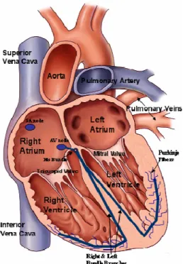
Figure 1 Cross Section of the Human Heart
The right ventricle propels blood from the heart to the lungs for exchange of O2 and CO2. This function is also known as the pulmonary circulation. The left
ventricle propels oxygenated blood to all other tissues of the body. This function is known as the systemic circulation. The flow of blood throughout the body is also unidirectional. This is accomplished by systematically arranged flap valves that prevent blood from flowing backwards.
2.2 The Heart Anatomy
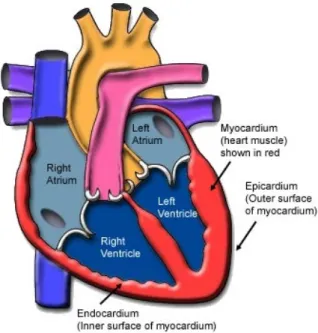
fibrous pericardium. This sac also protects the heart, anchors to its surrounding structures, and prevents the heart from overfilling with blood. The wall of the heart is composed of three layers, the epicardium, the myocardium, and the endocardium. The outer layer is called the epicardium or visceral pericardium since it is also known as the inner wall of the pericardium. The middle layer is the myocardium and it is composed of muscle that contracts. This is the thickest layer and it is known as the “workhorse” of the heart. The inner layer of the heart is the endocardium and it is composed of tissue that is in contact with the blood the heart pumps. It has a smooth surface which allows easy blood flow
throughout the heart chambers. See figures 2 and 3 below.
Figure 3 Cross Section of Heart Wall2
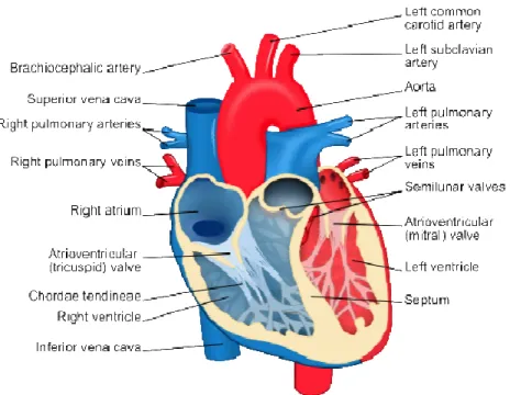
The heart has four chambers. The upper chambers are known as the atria while the lower chambers are known as the ventricles. The right atrium receives deoxygenated blood from the body via the superior and inferior vena cava. Blood is passed to the right ventricle through a valve where the blood is pumped to the lungs to collect oxygen. In a similar fashion, oxygenated blood from the lungs returns to the left atrium and it is pumped through a valve to the left ventricle. The left ventricle pumps the oxygen rich blood to the rest of the body through the aorta.
Blood flow within the four chambers of the heart is also unidirectional, from the atria to the ventricles and from the ventricles to the arteries. This is
Figure 4 Heart Chambers and Valves2
Chapter 3: Electrophysiology of the Heart
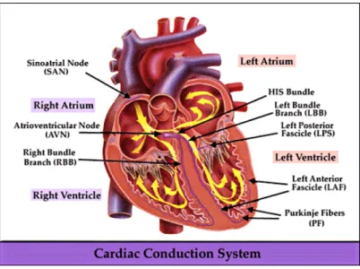
Figure 5 Cardiac Conduction System4
After the delay, the AV node sends an electrical signal through the “bundle of his” to the bundle braches and then to the Purkinje fibers. The action potential is then propagated to the endocardium at the apex of the heart and then to the
fail, the AV node or Purkinje fibers at their low frequency output would not provide the necessary cardiac output required by the human body.
Occasionally, other parts of the heart develop a rhythmical discharge rate that is much faster than the SA node. Often enough this occurs on the AV node or the Purkinje fibers when these become abnormal. In this instance, the natural pacemaker of the heart shifts from the SA node to the AV node or Purkinje fibers. Under rare conditions, a random point in the atria or ventricle develops excessive excitability and becomes the pacemaker, known as ectopic foci. A pacemaker elsewhere than the SA node is called an “ectopic pacemaker”.6 An ectopic
Chapter 4: The Coronary System
Perhaps the most common cause of congestive heart failure is coronary artery disease. This disease is the narrowing of the small blood vessels that supply oxygenated blood to the heart. A brief understanding of the coronary system and its physiology will give us a better understanding of the challenges today’s engineers face in developing new treatments for CHF.
While the circulatory system is busy providing oxygen and nourishment to all the cells in the body, the heart is working its hardest pumping the blood. And to work properly, the heart also needs blood and nourishment. After all, the heart is another organ in the body. The coronary system is the blood vessels within the heart that circulate blood to the heart and from the heart. This system of blood vessels includes arteries and veins. Arteries are blood vessels that carry oxygenated blood from the heart to the heart cells. Veins are blood vessels that bring back deoxygenated blood to the heart. The coronary circulation refers to the movement of blood through the heart tissue. The circulation of blood through the heart is just one part of the overall circulatory system of the body.7
4.1 Coronary Circulation (How it Works)
the left coronary artery. These two arteries branch into smaller arteries and finally into capillaries which supply the oxygen rich blood to the heart tissue. In a similar manner, the coronary veins bring back the oxygen free blood from the heart tissue back to the right side of the heart to be pumped into the lungs.
The right coronary artery or RCS supplies blood to the right side of the heart. The RCA lies in the right atrioventricular (AV) groove between the right atrium and right ventricle. The left coronary artery or LCA itself branches into two separate arteries, the left anterior descending artery (LAD) and the circumflex artery.
Figure 6 Coronary Arteries of the Heart30
ventricle. The circumflex lies in the AV groove between the left atria and left ventricle.
The coronary sinus vein returns most of the coronary venous blood from the left ventricle to the right atrium. The coronary sinus returns approximately 75% of the total coronary blood flow to the heart. 6 The coronary sinus is located in the right atrium and runs transversely in the groove between the left atrium and left ventricle. It also prolongs down the posterior apex of the left ventricle. Most of the coronary blood flow from the right ventricle returns to the heart through the anterior cardiac veins that flow directly into the right atrium.
4.2 Coronary Artery Problems
Coronary artery anomalies are rare. Early detection and evaluation is essential because of its association with sudden cardiac death. Today’s
technology advancements with computer imaging have made it possible to detect coronary anomalies through the use of CT scans. Coronary anomalies can be classified into anomalies of origin, the course, and termination. These
anomalies can be further classified as: 1. Anomalies of the Origin9
• Origin of coronary artery from pulmonary artery • Single coronary artery
2. Anomalies of the Course9
• Myocardial bridging • Duplication
3. Anomalies of Termination9
• Coronary artery fistula • Extra-cardiac termination
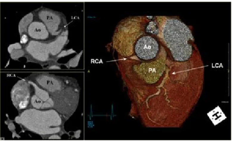
Interarterial left coronary artery is the most common and clinically significant anomaly. This is an anomalous origin of the left coronary artery
Figure 8 Interarterial Left Coronary Anomaly9
Another origin anomaly is known as “ALCAPA”. In this anomaly, the left coronary artery begins only from the pulmonary artery. As a result, the left side of the heart is supplied with relatively low oxygenated blood under low pressure. This anomaly more than frequently leads to sudden cardiac death. ALCAPA is a rare congenital anomaly accounting approximately 0.25% – 0.50% of all
congenital heart diseases.9 Approximately 85% of patients’ present clinical symptoms of congestive heart failure or CHF within the first 1-2 months of life.9
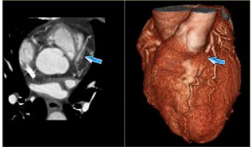
An anomaly of the course is myocardial bridging. This anomaly occurs when a section of the artery buries itself under the myocardium. A normal healthy artery typically rest on top of the myocardium. This is commonly
observed in the left anterior descending (LAD) coronary artery. If this happens, the depth of the artery under the myocardium is more important than the length of the myocardium bridging. Clinicians are still debating whether myocardium bridging has any hemodynamic significance.
Figure 10 Myocardial Bridging Coronary Anomaly9
the right atrium. Small fistulas are typically benign and can only be detected in routine echocardiograms or autopsies. On the other hand, larger fistula can progressively enlarge and lead to CHF and myocardium infarctions. It can potentially be deadly in older patients.
Figure 11 Fistula Coronary Anomaly9
Chapter 5: Congestive Heart Failure
5.1 Definition of Congestive Heart Failure
What is congestive heart failure? Congestive heart failure or CHF is a condition in which the heart can no longer pump enough blood to the rest of the body. It is a heart disease that can affect the right ventricle, the left ventricle, or both. It is most commonly a chronic condition that develops overtime, but it can also happen suddenly in rare cases. When CHF affects the right heart side, the right ventricle loses its ability to pump blood to the lungs. A common symptom of right side failure is the swelling of the feet and lower legs. As the condition
worsens, the upper legs swell and eventually the swelling moves to the abdomen area. When heart failure affects the left side, the left ventricle decreases its ability to pump blood to the body. The left ventricle receives highly oxygenated blood from the lungs ready to be distributed throughout the body. A common symptom of left side heart failure is breathing difficulty. As the left ventricle fails to empty its chamber, fluid starts collecting in the lungs which may lead to “pulmonary edema” if left untreated. The extra fluid in the lungs or “congestion” prevents the airways to expand normally as a person inhales. This creates the shortness of breath especially when the person is being active.
pump out. In most cases, the heart can contract normally but it has become stiff and less compliant. In either case, the danger is that your heart cannot pump enough blood to the rest of the body, especially when the person is active. As the pumping ability of the heart is diminished, blood may start to back up in different areas of the body producing congestion of the lungs, the liver, and the body’s extremities like arm and legs. As a result, there is a lack of oxygen being supplied to these organs or body cells which reduces their ability to function properly. The long term prognosis can be deadly as organ failure may be the result of an untreated condition.
A common clinical measurement for the heart’s ability to pump blood effectively is called the “ejection fraction” or “EF”. The ejection fraction is a calculation of how much blood is ejected from the left ventricle, also known as “stroke volume”, divided by the maximum volume remaining in the left ventricle at the end of the relaxation phase or “diastole”. A normal ejection fraction is greater than 50%.6,11 Systolic heart failure is diagnosed when the EF is less than 50%. In diastolic heart failure, the ejection fraction is typically normal. Diastolic heart failure is more common in patients older than 75 years, especially in women who suffer from high blood pressure.
failure. And every year about 550,000 new cases are diagnosed.11 The rate of death from heart failure is about 10% after the first year being diagnosed. About 50% of people with CHF will die within 5 years after being diagnosed.11 This statistics do vary by patient’s exact diagnosis and therapy, nonetheless it is classified as a high death risk disease. Many advances have been made in research and development for new therapies, both in drug or medical device treatments. This is a welcome sign of relief for patients who have to live with this life debilitating condition.
5.2 What Causes Congestive Heart Failure?
Congestive heart failure is not a disease but rather a syndrome that can be developed by several factors. CHF is a weakening of the heart caused by the following or a combination of several:
• Weakened heart muscle: the heart muscle can become weak because of damage and thus loose its capability to contract as it should. This damage to the muscle more often enough occurs from coronary artery problems.
the blood flow through the narrow opening. The heart has to work harder to ensure enough blood passes between the chambers and to the rest of the body.
• Blocked coronary vessels: the coronary arteries provide the blood to the heart for it to work properly. If the heart does not get its normal supply of oxygenated blood, it may in turn start to fail.
• Toxic exposure: excessive intake of drugs • Infections
• High blood pressure: increase blood pressure in the circulatory system can lead to an increased heart size or thickened left ventricular wall. This condition reduces the compliance of the ventricle wall and the ventricle’s ability to contract.
• Prolonged arrhythmias: slow weakening of the heart
Congestive heart failure can also developed by lifestyle choices. Unhealthy habits such as smoking or excess use of alcohol can lead to heart failure. An unhealthy diet and a lack of exercise that leads to obesity can contribute to heart failure. Not because of increased weight but rather the accompanying factors of obesity such as increased blood pressure and diabetes.
5.3
How to Treat CHF?
underlying causes, relieve the symptoms, and prevent further damage to the heart. In order to determine the best treatment option, physicians usually classify the type of CHF according to the New York Heart Association (NYHA) classification system.
Table 1 The Stages of Heart Failure - NYHA Classification13
Class Patient Symptoms
Class I (Mild) No limitation of physical activity. Ordinary physical activity does not cause undue fatigue, palpitation, or
dyspnea (shortness of breath). Class II (Mild) Slight limitation of physical activity.
Comfortable at rest, but ordinary physical activity results in fatigue,
palpitation, or dyspnea.
Class III (Moderate) Marked limitation of physical activity. Comfortable at rest, but less than
ordinary activity causes fatigue, palpitation, or dyspnea. Class IV (Severe) Unable to carry out any physical
activity without discomfort. Symptoms of cardiac insufficiency at rest. If any
Chapter 6: Cardiac Resynchronization Therapy
6.1 Definition of CRT
One way to treat heart failure is to place a device in the chest to assist with the electrical activity of the heart. People who suffer from heart failure normally develop a problem with their heart’s electrical function. Whereas traditional devices only applied therapy to treat electrical anomalies of the right side of the heart, a new type of therapy called cardiac resynchronization (CRT) is available for heart failure patients. CRT involves the use of electrical signal to stimulate and pace both the right and left ventricles. Roughly three to four out of every ten people with heart failure have an electrical problem in the conduction of electrical impulses to the lower chambers of the heart.12
progression of CHF that can lead to more severe problems. Ultimately, CRT is bringing an improved quality of life by treating the symptoms associated with CHF.
There are two types of CRT devices available. The first one delivers only electrical signals and is called a CRT pacemaker. The other combines a
pacemaker with a defibrillator for those patients who are at high risk of sudden cardiac death due to a fast heart arrhythmia. A defibrillator is a device commonly used to shock patients out of a deadly fast rhythm. This device is called a CRT implantable cardioverter defibrillator or CRT ICD.
The CRT system consist of three parts, the pulse generator which delivers the electrical signals, the lead which carry the electrical signals from the
A non CRT pacemaker usually has two electrical leads going from the device to the heart, one placed in the right atrium and another placed in the right ventricle. These two electrical leads will ensure the heart maintains a normal coordinated pumping relationship between the upper and lower chambers. A CRT device has an additional electrical lead that connects the device to the left ventricle. This third lead is routed through the coronary sinus and placed on the outer surface of the left ventricle. The third lead allows the device to coordinate the electrical stimulus of the left ventricle and bring both ventricles back into a synchronous pumping action. This type of therapy is sometimes referred as “bi-ventricular” or “bi-v pacing” because both ventricles are being stimulated.
The development of CRT arose from the studies that showed 40% of CHF patients had an interventricular electrical conduction problem. This condition often led to worsening CHF symptoms that terminated in death. A typical candidate that would benefit from CRT suffers from NYHA class III or class IV heart failure and their ejection fraction is below 50%.
6.2 CRT Benefits
Many clinical trials have been performed to prove the benefits of cardiac resynchronization therapy. The results of these trials over the last decade have shown reduction in hospitalization occurrences and mortality rate on patients who received CRT.
failure. The trial examined the safety and efficacy of CRT combined with traditional ICD therapy. The results found an improved quality of life after six moths of combined CRT and ICD therapy as evaluated by the “Minnesota Living with Heart Failure Questionnaire”. The results also showed improved functional capacity and exercise tolerance in patients with advanced HF. However, the trial endpoints did not include mortality or hospitalization measurements. The safety and efficacy of CRT was raised in part due to questions with lead placement and possible interference from the addition of bi-v pacing and ICD therapy. The trial showed that CRT does not interfere in the delivery shock therapy but concluded that left ventricular lead placement is not without its challenges. Transvenous LV lead implantation was unsuccessful in 12% of the patients in the study.14 It was also noted that once implanted, LV leads were prone to dislodgement.
The COMPANION study was the largest CRT device trail and the first designed to study the mortality and hospitalization rates as the primary endpoints. It was originally forecasted that up to 2200 patients would be
required, although that study was conducted with 1634 patients. All the patients in the study were under optimal pharmacological therapy (OPT) with the
additional therapy of CRT-P or CRT-D for a selected group. The primary endpoint of death or any hospitalization showed a reduction of about 19% for both CRT-P and CRT-D patients as compared to the OPT alone therapy
results of the COMPANION trial gave additional proof regarding the benefits of CRT .
Additional clinical trials like the MUSTIC trial and the CARE-HF trial have provided additional data supporting the value of CRT. The MUSTIC results concluded that CRT improved exercise tolerance and quality of life for patients with chronic heart failure and interventricular conduction delay. The trial also concluded a 66% reduction in hospitalization occurrences due to heart failure complications.16 The CARE-HF trial also focused on mortality and hospitalization as endpoints for CRT benefit. The trial compared CRT to normal OPT treatment in 813 patients. The trial showed a reduction of 46% in combined death or heart failure hospitalization. CRT was also associated with a 37% reduction in the risk of mortality.17
Cardiac resynchronization therapy can substantially improve the quality of life for patients suffering from NYHA class III or class IV heart failure. The
physiological benefits of CRT can be seen in the improved tolerance for exercising. Additionally, CRT has proven to reduce the rate of mortality and decrease the occurrence of hospitalization.
6.3 CRT and LV Pacing Complications
The benefits of CRT to treat congestive heart failure are numerous,
anatomy make it difficult for physicians to implant an LV lead through the
coronary sinus. In such cases, these patients are eliminated from candidacy for traditional CRT. In other instances, although the majority of the population has a normal working coronary system, small anatomical differences in the coronary vein produce a challenge to the implanting physician to locate the LV lead appropriately. These challenges are associated with differences in the vein diameters and vessel turns. The implant procedure for an LV lead is more challenging because physicians must locate a region where good capture thresholds can be achieved and the site of most delay for left ventricular mechanical activation.18 Without a well positioned LV lead, CRT devices lose their ability to perform cardiac resynchronization. Other complications with LV implant include lead dislodgement, coronary sinus thrombosis, loss of pacing capture, and stimulation of the diaphragm.
Other treatment methods are constantly being developed and tested to provide alternative pacing options to the left ventricle. In an effort to maximize hemodynamic benefit of CRT, the use of an epicardial LV lead may be an option. An epicardial lead is surgically attached directly to the epicardium of the heart. This procedure requires a thoracotomy and general anesthesia as compared to local anesthesia for traditional CS LV leads. Once access to the heart is
Chapter 7: Epicardial Pacemaker
7.1 Overview of Traditional CRT Therapy
Cardiac resynchronization therapy attempts to restore the synchronous pacing of both ventricles. First a pacemaker, along with right and left side leads must be implanted. A CRT system consists of a pulse generator and three pacing leads. The generator contains a battery and microelectronic computer that serves as the “devices” brain. The leads are insulated wire coils that carry electrical impulses produced by the pulse generator to the heart and carry information from the heart back to the pulse generator. In a CRT system, one lead goes to the right atrium, the second lead to the right ventricle, and the third lead to the left ventricle. Right heart leads are implanted intravenously via the superior vena cava and anchored to the endocardium of the heart. CRT left side leads are most commonly implanted via the coronary sinus to the post lateral side wall of the left ventricle. Many clinical trials have shown the benefits of CRT for patients suffering from NYHA class III or class IV heart failure. These CRT candidates can benefit from ventricle resynchronization by ways of an improved quality of life and less hospitalization events arising from HF complications.
limitation is present, it is possible for anyone with a CRT device to live a normal active life.
Several methods of implanting a CRT system are available. The choices depend primarily upon health, age, and patient’s anatomy. The most common involves implanting the insulated leads into the heart through the veins of a patient who is under mild anesthesia. The pulse generator is implanted under the skin in a specially prepared pocket in the right or left upper chest. The leads are connected to the pulse generator and the device secured to the pocket by sutures. This surgery typically takes about 2 hours and it is often performed in a cardiac lab. Fifty percent of this time is usually spent locating the appropriate LV lead site and advancing the lead. Another method involves the use an of
epicardial lead instead of a transvenous LV lead. The implantation procedure for an epicardial lead requires extensive surgery and is performed with the patient under complete anesthesia.
7.2 The Epicardial Satellite Pacemaker Concept
could be associated with a small CS diameter which prevents lead advancement. The trajectory of the CS could be abnormal whereas it prevents establishing an optimal LV pacing site or the physician may not be able to keep the lead in a stable position. An epicardial lead surgically attached to the heart addresses the above concerns. However, this procedure requires major surgery and prolonged recovery times for the patient. The epicardial satellite pacemaker concept is intended to resolve the conduction problems, anatomical differences within patients, and the surgical risks and side effects associated with a thoracotomy.
7.3 How the Epicardial Pacemaker Works
A CRT system is an implantable cardiac system that treats patients with congestive heart failure (CHF). This particular cardiac system is composed of a master device, intravenous leads, and a satellite pacing device. The master device provides the pacing pulses to the right side of the heart via transvenous leads anchored to the endocardium of the heart. The master device also contains a communication module that sends pacing commands to the satellite device. The satellite device is a leadless pacing output device anchored directly to the left ventricular epicardial wall of the heart. This satellite device mentioned above is the epicardial pacemaker or EPI pacemaker.
system supports multi chamber detection and stimulation therapy, including biventricular pacing to treat a patient with CHF. The EPI pacemaker can be implanted onto the left ventricle using thoracoscopic procedures during implant of the master device. In special events, the EPI pacemaker may be implanted using prophylactic techniques during bypass heart surgery or in cases where heart access is available. The EPI pacemaker communicates with the master device using wireless communication methods like RF. This is represented by link 110. The EPI pacemaker is not intended to deliver shock therapy, but in cases where a CRT-D device is used as the master unit, the EPI pacemaker may contribute to shock therapy by enabling better detection of arrhythmias. By noting ECM irregularities between the EPI pacemaker and the right ventricle lead, fibrillation may be able to be detected with confidence.
The EPI pacemaker is capable of pacing the left ventricle under direct command of the master device. Depending on its programmable settings, the EPI pacemaker may be set to respond to various inputs. It may be programmed to directly pace according to an output set by the master device or it may be programmed to sense artifacts from the right ventricle lead and apply a pacing pulse in response. Yet another programming setting could be a combination of both, sensing artifacts and direct commands from the master device.
7.4 Description of the Epicardial Pacemaker
In its most simple embodiment and functionality, the EPI pacemaker is a passive device. It is configured to only pace the left ventricle in response to commands from the master device. The EPI pacemaker has a housing made out of commercially pure titanium. The housing protects the microelectronic
The EPI pacemaker also includes a battery to supply operating power to all the electrical components. The battery is capable of operating at low current drains for long periods of time. The battery is also capable of providing pulses with sufficient voltage to stimulate the left ventricle.
Figure 15 Battery for Epicardial Satellite Pacemaker
The microelectronics of the EPI pacemaker is considered the brain of the device. It is tasked for receiving signals from the master device and in turn producing a pacing output to stimulate the left ventricle. It consists of a single layer PCB, a PIC controller and a capacitor.
An electrode is mounted to the front surface of the device to deliver the pacing pulses. The electrode has a helical shape to facilitate perforation of the pericardium and to be screwed into the epicardium. Additionally, it provides an active fixation anchor to the heart tissue. The electrode is assembled to a titanium lid by brazing a ceramic ring to isolate the two metals. The helical electrode is made of 80% platinum and 20% iridium.
Figure 17 Epicardial Satellite Pacemaker (Exploded View)
7.5 Benefits over Traditional CRT Leads
the active EPI pacemaker, that particular one can be turned off and a new one activated.
Another benefit of an EPI pacemaker cardiac system is multi-site pacing. The system can be configured to support triple timing ventricular pacing to obtain optimal heart hemodynamics. One EPI pacemaker can be positioned one
centimeter down from the ventricular base by the cardiac vein. A second EPI pacemaker can be positioned 3 centimeters down by the same vein. Then, the first EPI pacemaker is paced and the second one paced 10 milliseconds later. Finally, the RV tip electrode is paced 15 milliseconds later. This pacing method is extendable to four or more EPI pacemakers if desired.
The ability to implant the EPI pacemaker using thoracoscopic procedures is a great improvement over thoracotomy procedures needed for an epicardial lead. Because the EPI pacemaker is wireless, there is no need for tunneling the lead to the device pocket. Therefore the EPI pacemaker can be implanted using thoracoscopy over thoracotomy. This minimizes trauma to the patient and
Chapter 8: Future Work
8.1 Vibration Studies on the Heart Tissue
The heart is a muscle that is constantly in motion. A normal heart beats an average of 60-70 beats per minute. Under stressful conditions from
exercising, the rate can increase to 130-150 beats per minute. An active fixation of the epicardial pacemaker is essential for continuous therapy to the left
ventricle. The thickness of the epicardium and myocardium is approximately 1.5 centimeters. Therefore, a relatively small helix is desirable to minimize
perforation of the heart muscle and reduce trauma. On the negative side, it provides less tissue capture to secure the device to the heart wall. Vibration tests need to be performed with canine or pig hearts to determine the relationship between excitation frequency and electrode length.
The epicardial pacemaker is intended to be implanted using a
thoracoscopic procedure. This means the physician needs to deliver the device through the rib cage and affix it to the epicardium. One unknown factor is the amount of torque required to screw the device to the epicardium. This
higher frequencies. The human body, on the other hand, is very conductive. The distance between the master device and the epicardial device and the total resistivity between the two can affect how the two devices communicate.
Scientific studies have estimated resistivity values of the myocardial tissue. One study determined that with 100Hz stimulation at 2 V, myocardial resistivity was approximately 295 Ω•cm. Based upon resistivity, we can estimate the predicted resistance of tissue between the master device and the epicardial pacemaker
(20)
(20)
be calculated to be 393.3 Ω. The further the master device is from the epicardial pacemaker, the larger resistivity between the two. In a similar manner, the heavier the patient, the more fatty tissue present between both devices. These values are low in comparison to other RF applications which could limit the communicating effectiveness. These initial differences could be resolved by programming capabilities within the master device. But in time, if patient’s resistivity fluctuates, communicating frequencies may vary which will require physician intervention. The danger is for pacer dependent patients where the possibility of losing communication between devices and not delivering therapy may occur.
8.3 Gel to Promote Adhesion and to Reduce Scar Tissue
One potential problem with the epicardial pacemaker and its screw in electrode is irritation to the heart tissue that occurs due to the movement of the electrode as the heart beats. This irritation causes the body to build scar tissue around the affected area, in this case around the electrode. As scar tissue builds up, higher voltages are required to pace the heart. This could result in lower battery life for the epicardial pacemaker and perhaps the need for more frequent replacements.
to the heart tissue and absorb shocks as the heart beats and moves. The gel material can also promote tissue growth and allow tissue to grow into the gel to hold and anchor the device to the heart muscle. The gel material may also contain a steroid, such as dimethyl sulfoxide (DMSO) to reduce the immune response of the body and aid in preventing irritation and inflammation to the implant area.19
8.4 Future Design Considerations (The Pericardium)
Although the benefits of an epicardial pacemaker seem to provide a safe and viable option to traditional transvenous LV leads, the approach has its challenges. These include whether the pericardium needs to be surgically opened and closed after implant. The pericardium serves several mechanical functions. Besides constraining the heart in the thoracic cavity, it has
hemodynamic influences on the ventricles during diastolic filling. Several studies
have been done to assess the benefit of closing the pericardium or leaving it open after thoracotomy.
One study concluded that pericardial closure is unlikely to have any significant harmful effects in the majority of patients who maintain a good circulatory state after surgery. For these patients, it is reasonable to close the pericardium as long as the pericardium does not appear to be taut. However, for ill patients who started with a low cardiac output, closure of the pericardium had adverse effects by reducing cardiac output as much as 14%.21 The study suggested that cardiac function may be impaired by pericardial closure after cardiac surgery because of some degree of constriction of the heart chambers. For these patients it was recommended to leave the pericardium open to avoid any further stress to the blood circulation.
Another study showed the significant effect on diastolic filling of the left ventricle when the pericardium was closed. However, when the pericardium was opened, it resulted in an increase cardiac index (cardiac output divided by body surface area). The increases can be attributed to the Frank-Starling mechanism to increased left biventricular preload.22 With the pericardium open, the ventricle is less restricted and allowed to fill with more blood. This in turn has an
improvement in left ventricular systolic performance which should be considered when contemplating closure of the pericardium.23
surgical interventions such as coronary artery by-pass. However, it should be considered to be left open for patients who in early postoperative periods show impaired ventricular function.24
8.5 Future Design Considerations (The Rib Cage)
The rib cage is a bony structure that protects the heart, lungs, and other underlying organs. It is made of three groups of bones, the sternum, twelve (12) pairs of ribs, and twelve (12) thoracic vertebrae. Implantation of an epicardial pacemaker is desired to be accomplished by thoracoscopic procedures. To accomplish this, the device needs to be small enough to pass through the intercostal spaces between the ribs.
An intercostal space is wider in the upper ribs. As we move down the rib cage, the intercostal spaces start to reduce in size. One point to consider in making an incision through the intercostal space is the neurovascular bundle of vein-artery-nerve. Therefore it is desired that the intercostal space be penetrated as low as possible. This reduces the opening for the epicardial pacemaker to pass through. Typically, epicardial leads are implanted through the fourth intercostal space.25, 26 It is desired that any thoracoscopic heart surgery to
Figure 19 Intercostal Space in Human Ribs
The initial design and prototyping of the epicardial satellite pacemaker have conceptually addressed its success. A small device was fabricated capable of being programmed to deliver a constant 3V pulse. Radio frequency
communication capabilities on current pacemakers and implantable cardioverter defibrillators make them suitable candidates to function as a master device. Therefore, the foundation for a wireless epicardial pacemaker is feasible. There is a lot of work and design refinement that needs to be done before we can move past conceptual phase and into testing trials. Addressing the future work
Chapter 9: Conclusions
Although people are at a higher risk of developing CHF on the later years of life, heart failure is a disease that affects everybody without discrimination to gender or age. Many drugs are available to address the symptoms, but the most successful therapy has been proven to be cardiac resynchronization. CRT is a fairly young technology and it is constantly evolving to provide physicians with the best tools to treat CHF.
The epicardial wireless pacemaker concept takes a step in addressing today’s challenges with coronary sinus LV implants and epicardial leads. By directly stimulating the heart tissue, we can obtain lower capturing thresholds. An epicardial pacemaker can also be positioned on the site for optimal ventricle stimulation regardless of coronary anatomies. A plurality of epicardial
pacemakers can be implanted to give physicians multisite pacing options.
Finally, the lack of wires eliminates the need to tunnel from the implant site to the master device pocket. This facilitates a less invasive surgical procedure to implant the device.
References
1. “Heart”, Wikipedia Foundation, Inc. December 2010 <http://en.wikipedia.org/wiki/Heart>
2. “Heart Health Center”, WebMD. 2009
<http://www.webmd.com/heart/picture-of-the-heart>
3. Levy, M. & Pappano, A. Cardiovascular Physiology. 9th ed., Mosby Elsevier, Philadelphia, (2007)
4. “Cardiac Conduction System Diagram”, Marquette Electronics. 1996 <http://library.med.utah.edu/kw/ecg/mml/ecg_ccs.gif>
5. “Electrical conduction system of the heart”, Wikipedia Foundation, Inc. November 2010
<http://en.wikipedia.org/wiki/Electrical_conduction_system_of_the_heart> 6. Guyton, A, and Hall, J. Textbook of Medical Physiology. 10th ed., W.B.
Saunders Company, Philadelphia, (2000).
7. “Coronary Circulation: It’s All in the Heart”, The Franklin Institute. 1996-2010
<http://www.fi.edu/learn/heart/systems/coronary.html> 8. Wesley, N., “Pericardial Sinuses”,1999
<http://home.comcast.net/~wnor/thoraxlesson4.htm>
9. Smithius, R & Willems, T. “Coronary anatomy and anomalies”, The radiology Assistant. October 14, 2008
<http://www.radiologyassistant.nl/en/48275120e2ed5>
10. Gupta-Malhotra, M. “Coronary Artery Fistula”, WebMD. January 12, 2010 <http://emedicine.medscape.com/article/895749-overview>
11. “Congestive Heart Failure”, WebMD. 2010
<http://www.emedicinehealth.com/congestive_heart_failure/article_em.htm
12. “Pacemaker for the Treatment of Heart Failure”, Blue Cross Blue Shield of Tennessee. February 18, 2010
13. “New York Heart Association Functional Classification of Heart Failure”, SSCTS.
<http://sscts.org/ClassificationHeartFailureNYHA.aspx>
14. “Combination CRT/ICD Therapy Shows Promise in Moderate to Severe Heart Failure Patients with ICD Indications: Results of the MIRICLE ICD Trail”, Medscape. 2003
<http://www.medscape.com/viewarticle/456492>
15. “COMPANION: Comparison of Medical Therapy, Pacing, and Defibrillation in Chronic Heart Failure”, Medscape. 2003
<http://cme.medscape.com/viewarticle/452023>
16. Lowry, F. “Multisite biventricular pacing improves heart failure: MUSTIC trial”, The Heart Org. March 22, 2001
<http://www.theheart.org/article/289149.do>
17. “CARE-HF: Long tern Effects of Cardiac Resynchronization on Mortality and Echocardiography and Cost-effectiveness Analyses”, Medscape. 2005
<http://www.medscape.com/viewarticle/513976>
18. Mair, H., Sachweh, J., et al. “Surgical epicardial left ventricular lead versus coronary sinus lead placement in biventricular pacing”, European Journal of Cardio-Thoracic Surgery. 2005
<http://www.ejcts.ch/cgi/content/full/27/2/235)>
19. Nabutovsky, Y., Williams, S., et al. “Tissue Contact for Satellite Cardiac Pacemaker”, United States Patent US 7,200,437, (April 3, 2007)
20. Avallone, E & Baumeiter, T. Mark’s Standard Handbook for Mechanical Engineers. 9th edition, chapter 15, McGraw-Hill Inc., New York, (1987) 21. Angelini, G., Fraser, A., et al. “Adverse Hemodynamic Effects and
Echocardiography Consequences of Pericardial Closure Soon After Sternotomy and Pericardotomy.” Circulation (1990):82 (suppl IV):IV397-IV406
22. Klabunde, R. “Frank-Starling Mechanism”, Cardiovascular Physiology Concepts. April 6, 2007
24. Rao, V., Komeda, M., et al. “Should the Pericardium Be Closed Routinely After Heart Operation?” The Society of Thoracic Surgeons. 1999;67:484-8 25. Dodge-Khatami, A., Kadner, A., et al. “Left heart atrial and ventricular
epicardial pacing through a left lateral thoracotomy in children: a safe approach with excellent functional and cosmetic results” European Journal of Cardio-Thoracic Surgery. 28 (2005) 541-545
26. Gabor, S., Prener, G., et al. “A simplified technique for implantation of left ventricular epicardial leads for biventricular resynchronization using video-assisted thoracoscopy (VATS)” European Journal of Cardio-Thoracic Surgery. 28 (2005) 797-800
27. Navia, J. & Atik, F. “Minimally Invasive Surgical Alternatives for Left Ventricle Epicardial Lead Implantation in Heart Failure Patients” The Society of Thoracic Surgeons. 2005;80:751-4
28. Dekker, A. & Phelps, B., et al. “Epicardial left ventricular lead placement for cardiac resynchronization therapy: Optimal pace site selection with pressure volume loops” The Journal of Thoracic and Cardiovascular Surgery. June 2004;vol 127, no 6:1641-1647
29. Doll, N., Opfermann, U., et al. “Facilitated Minimally Invasive Left
Ventricular Epicardial Lead Placement” The Society of Thoracic Surgeons. 2005;79:1023-5
30. “The Coronary Arteries”, Texas Heart Institute. July 2010
<http://www.texasheartinstitute.org/HIC/Anatomy/coroanat.cfm> 31. “Myocarditis”, Texas Heart Institute. July 2010