Virtual Eye
Gargi V Pillai Lincy Grace Alexander
Model Engineering College, Cochin Model Engineering College, Cochin
Soja Sasi Reshma S
Model Engineering College, Cochin Model Engineering College, Cochin
Abstract
This project aims at making a blind person independent in most aspects. The proposed system is based on object identification implemented on Field Programmable Gate Arrays (FPGA), an area not widely explored for object identification. The aid constitutes of a camera that acts as a virtual eye which communicates with the outside world. The camera acts as a constant source of information to the system. It takes in 5-6 frames per second and correlates it with the template image in database. Thus the information about surroundings is identified and informed through the headset (output unit) by which the blind person can go about doing his daily activities.
Keywords: FPGA, Cross correlation, Xilinx, VHDL
________________________________________________________________________________________________________
I. INTRODUCTION
It is estimated that there are 180 million people in the world currently who are affected by problems with their vision. Within this number, approximately 40–45 million are blind, by definition unable to go about their life unaided. With an estimated 7 million people going blind each year, the number of people visually impaired is expectedly to double by the year 2020. Mobility aids like walking stick and guide dogs are commonly used by the blind even today. With the advances of modern technologies many different types of devices and software are available to support the blind.
Fig. 1.1: Real time Digital Eye System II. BACKGROUND AND RELATED WORKS
The goal of our project VIRTUAL EYE is to act as a virtual eye for blind people. This project has features which helps the visually impaired to acquire an artificial vision through sense of hearing. Our product will be custom made for specified person.
In our research through literature, and ethnographies with the visually impaired and rehabilitation service workers we identified that one of the major problems the visually impaired experience is trouble with object identification and indoor navigation in buildings. There has was little done in regards to these in current assistive technologies possibly due to high cost for instrumentation and limited capabilities. Our goal is to break down these barriers by introducing a custom made system to help blind people in object recognition and act as a virtual eye by using a camera, object detector, headphone and FPGA.
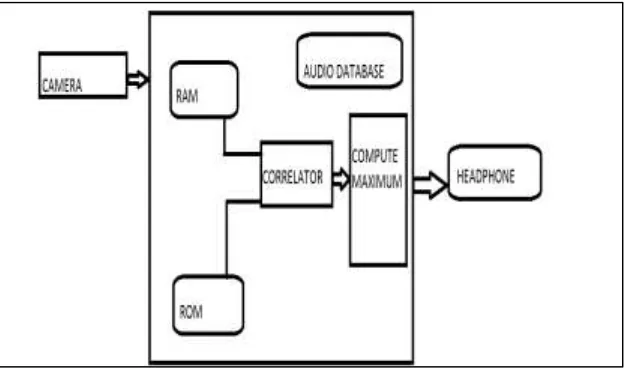
Fig. 1: Block Diagram of FPGA
A Field-programmable Gate Array (FPGA) is an integrated circuit designed to beconfiguredby the user after manufacturing-hence, "field-programmable" as given in [4].FPGAs contain programmable logic components called "logic blocks", and a hierarchy of reconfigurable interconnects that allow the blocks to be "wired together"—somewhat like many (changeable) logic gates that can be inter-wired in (many) different configurations. Logic blocks can be configured to perform complex combinational functions, or merely simple logic gates like AND and XOR.
III. METHODOLOGY
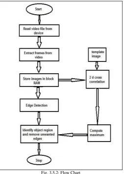
The video _le is read from the computer where it is stored priory. Frames from the video are extracted as 5-6 frames per second. The frames are taken and these images are stored ina block RAM which is then followed by edge detection. Edge detection is done by identifying the sharp differences in frequency of the pixels. By this the image outline is obtained andan unwanted region like background etc is removed. Alongside this, the template image is 2D cross correlated with the image in block RAM.
The maximum value is computed and checked if it matches with the template. The audio corresponding to the image is then played through the head phone.
Fig. 2: System Block Diagram Correlator:
Image Sensor OV6630:
The OV6630 (colour) CMOS Image sensors are single-chip video/imaging camera devices designed to provide a high level of functionality in a single, small-footprint package. The device incorporates a 352 x 288 image array capable of operating up to 60 frames per second image capture. Proprietary sensor technology utilizes advanced algorithms to cancel Fixed Pattern Noise (FPN), eliminate smearing, and drastically reduce blooming. It is programmable through an I2C interface. The device can be programmed to provide image output in 4-bit, 8-bit or 16-bit digital formats.
Interfacing:
This bus is a simple bi-directional bus that supports multiple masters and slaves. It uses only two bidirectional open-drain lines, Serial Data Line (SDA) and Serial Clock (SCL), pulled up with resistors. Our Master I2C controller is implemented in FPGA and the slave is the CMOS image sensor OV6630.At all times, the master is in control of SCL line.
Video Format:
The video format specifications are given by Resolution: 176 x 144
Frame rate: 25 fps, 8 bit QCIF digital output format Read out: progressive
Frame extraction and processing:
The frames are extracted from the video and the resulting images are resized to simplify the computations. FPGAs allow large-scale parallel processing and pipelining of data flow. Latest FPGAs provide enormous processing resources, significant on-chip RAM and support very high clock speeds. FPGAs are therefore suitable for implementing object detection systems discussed above. The system supports a 512x512 pixel frame size. Since each pixel contains one byte of data, the frame size is 262,144 bytes. However, even the significant
On-chip RAM provided in Xilinx Virtex FPGAs is not sufficient to support a useful level of internal RAM frame buffering in the object detection application described. So offline video processing is done using MATLAB. The frames are extracted from the video using ‘Video Reader’ and the images are stored in the internal RAM of the FPGA for further image processing.
Image Processing:
The objective is to match the main image with a template image called the reference image and the location where optimal matching is obtained by matching the reference image over the searching region of the input image using suitable similarity measures. The two conflicting requirements of image registration are the time and accuracy. Accordingly, one can employ a fine search (brute force) or a coarse-fine search (efficient in time) method. In fine search strategy, registration starts at the top left corner of the search space and continues long each row and column moving the sub image by one pixel each time. The accuracy of registration algorithm using fine search is good but the computation time is large. In coarse-fine search strategy, registration is done by extracting sub images of equal size as that of the reference image at the start of search space on a coarse grid at every match point. An approximate match point is found at the end of this step. Here we have chosen a coarse-fine search.
Algorithm:
Cross-Correlation:
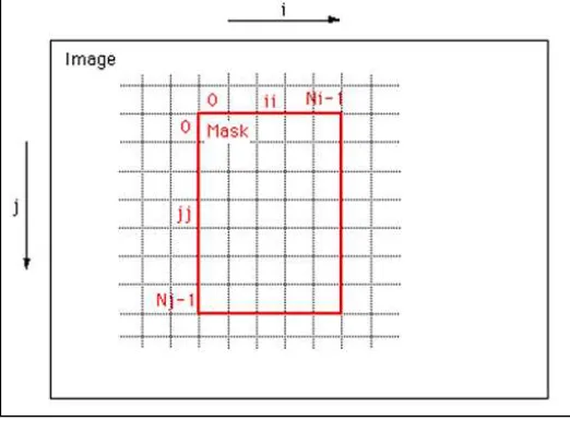
Template Matching by Cross-Correlation of the two images is done. A classical technique for registering a pair of functions is to form a correlation measure between functions and determine the location of the maximum correlation.
The peaks in this cross correlation" surface" are the positions of the best matches in the image of the mask. Edge Detection:
Edges characterize boundaries as well as giving the information of the location object, shape and size. Therefore, edge detection is a fundamental practice in image processing. Sobel edge detection involves convolution of 3x3 masks with the image resulting in an output image of the same size.
Fig. 3.5.2: Flow Chart Audio Section:
The audio files are stored in form of an MP3 file into a compact flash memory. Then we have to decode the MP3 bit stream into 16-bit pulse code modulated (PCM) outputs using a standard MP3 decoding algorithm, and play the output through an external speaker. Hardware description language VHDL is used to drive external peripherals, including the stereo Audio codec. The Audio codec converts the digital PCM outputs into an analog sound wave.
IV. EXPERIMENTAL OBSERVATIONS AND DISCUSSIONS
MATLAB Result:
Simulation results for feature extraction code: Frame Extraction:
The video (.avi file) is read into a multimedia object using MATLAB function VideoReader() and the frames are sampled by a fraction of its frame rate and stored into astructure.
DeBlurring:
The effect of blurring due to camera motion and additive noise is simulated andde-blurring using Weiner filter is done. Edge detection:
The various techniques to edge detection ware explored and results were observed. Object Detection:
MATLAB Simulation Results
Fig. 4.1: a) Original Image (b) Original Image 2(c) 100 strongest features of image 1 (d) 100 strongest features of image 2
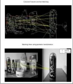
Fig. 4.2: (a) Extracted features and their matching (b) Matching Inliers Correlation:
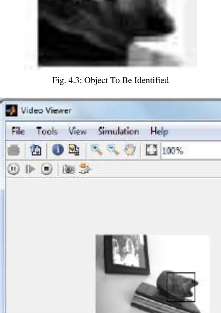
Fig. 4.3: Object To Be Identified
Fig. 4.4: Correlated Output Cross correlation in VHDL simulated output:
The two dimensional cross correlation algorithms is written in VHDL and simulated in Xilinx ISE.
V. FUTURE WORK
Nanotechnology can be used to minimize the dimensions of the module.
Medical monitoring system (ECG, BP, Sugar level) may be added to care the visually impaired patient.
The device can be equipped with GPS technology which will guide the blind man to his destination by giving directions through the headset.
Using Bluetooth instead of the headset can make the device more compact thus eliminating any discomfort experienced by the person.
System can be designed to interact with ATM machines in voice for convenience.
VI. CONCLUSION
The problem with the existing system is the delay encountered and insufficient efficiency. This vision system is designed on the basis of comparatively fast computations and minimized device modules. The system is compact in nature ensuring portability that blind people don’t look different, while they wear it. This design articulates the user to behave casually and individually without any restriction.
The object identification module of the proposed model was simulated and verified using both MATLAB and VHDL programming. The correlated outputs of both MATLAB and VHDL were compared with each other and it was found that there is 8% percentage of error. The position of the sample object was observed to be in the vicinity of the required position. All these result in a compact, safe, portable, cost-effective, totally a user friendly module satisfying the needs of the needy.
REFERENCES
[1] Subodh Kumar, PrabatPandey; FPGA Implementation Of Image Segmentation By Using Edge Detection Based On Sobel Edge Operator, IJRET: International
Journal of Research in Engineering and Technology
[2] Anthony Edward Nelson;Implementation Of Image Processing Algorithms On FPGA Hardware
[3] Hideaki Uchiyama;EricMarchand ,Object Detection and Pose Tracking for Augmented Reality:Recent Approaches
[4] Kah Pin Ng; Guat Yew Tan;Ya Ping Wong;2013 ;Vision-Based Hand Detection for Registration of Virtual Objects in Augmented Reality, International
Journal of Future Computer and Communication
[5] YiranLi ; FPGA Implementation for Image Processing Algorithms
[6] V.DhilipKanna,P.V.DeepakGovindPrasad,S.AswinAmirtharaj,N.Sriram Prabhu:2011;Design of a FPGA based Virtual Eye for the Blind, 2nd International
Conference on Environmental Science and Technology,IPCBEE vol.6 (2011) (2011) IACSIT Press, Singapore
[7] Christopher Schlumberger-Socha,Olivier Van-Goethem:2010;FPGA Project: Real Time Image Processing
[8] Bernard Blackham:2006;The Development of a Hardware Platform for Real-time Image Processing, Centre for Intelligent Information Processing Systems
School of Electrical, Electronic and Computer Engineering
[9] Carlos Lujan Ramirez, RamnAtocheEnseat and Francisco Jos Mora Mas;Acquisitionand Digital Images Processing,Comparative Analysis of FPGA, DSP,
PC for the Subtraction and Thresholding
[10] Martin Geier;Design and Implementation of an FPGA-based Image Processing Frame-work for the EyeBot M6