Article
1
Dynamic Gesture Recognition using a Smart Glove in
2
Hand-Assisted Laparoscopic Surgery.
3
Lidia Santos 1, Nicola Carbonaro 2,3, Alessandro Tognetti 2,3, José Luis González 1, Eusebio de la
4
Fuente 1, Juan Carlos Fraile 1 and Javier Pérez-Turiel1
5
1 ITAP, University of Valladolid, 47011 Valladolid Spain; [email protected]; [email protected], efuente
6
@eii.uva.es ; [email protected]; [email protected]
7
2 Research Centre E. Piaggio, University of Pisa, 56122 Pisa, Italy; [email protected]
8
(N.C.); [email protected] (A.T).
9
3 Department of Information Engineering, University of Pisa, 56122 Pisa, Italy
10
* Correspondence: [email protected]; Tel.: +34-983-423-355
11
Abstract: This paper presents a system developed for the assistance with a collaborative robot in
12
hand-assisted laparoscopic surgery (HALS). The system includes a sensing glove with
13
piezoresistive sensors which capture continuously the flexion degree of the surgeon's fingers.
14
These data are analyzed using an algorithm that detects and recognize the selected movements.
15
This information is sent as commands to the collaborative robot throughout the surgical operation.
16
The bending patterns, speed and execution times of the movements are modelled in a pre-phase in
17
which it will extract all the necessary information for later detection during the motion execution.
18
The results obtained with 10 different volunteers show a high degree of accuracy and a low false
19
discovery rate.
20
Keywords: Hand Assisted Laparoscopic Surgery (HALS); sensing glove; wearable; collaborative
21
surgical robot, gesture recognition.
22
23
1. Introduction
24
The field of robotics has been entering laparoscopic surgery to facilitate the surgeon's work. The
25
first robots were developed to provide greater stability and precision to the movements of
26
endoscopes or any other additional tools. They consisted of a simple robotic arm and an endoscope
27
or laparoscopic tool attached to it [1]. Since then, they have evolved into semi-autonomous robots
28
that assist the surgeon in the different phases of the operation [2][3][10].
29
The guidance of these robots is carried out by joystick, in which haptic feedback has been
30
developed [11] or using visual servo-control techniques [4] .
31
The use of cameras is an early developed technology to sense gestures, but it has not been
32
applied due to challenging problems such as changing light and background [5]. The same problems
33
appear in hand-assisted laparoscopic surgery (HALS), a special laparoscopic surgery in which the
34
surgeon introduce the non-dominant hand inside the patient’s abdomen. This allows the surgeon to
35
recover the sense of touch, which is not present during a standard laparoscopic operation. As the
36
entire hand will not always be visible, methods for recognizing hand gestures as [6][7][8][9][10] by
37
artificial vision are not appropriate, so in order to communicate with the collaborative robot in a
38
simple and intuitive way, the use of a sensor glove is proposed.
39
In the current paper, we have developed a dynamic gesture recognition algorithm using a
40
sensor glove to recognize the commands that the surgeon will send to the collaborative robot. Due to
41
the limited space and bearing in mind that the surgeon must have mobility within the patient's
42
abdominal cavity, a comfortable textile-based motion sensing glove has been chosen, which adapts
43
to the surgeon's hand. The glove we adopted in this study was tailored to a different application (i.e.
44
daily-life monitoring of the grasping activity of stroke patients, as described in [11]) and has a low
45
number of sensors, i.e. three sensors covering the thumb, index and middle fingers. This wearable
46
device allows monitoring the surgeon's hand movements throughout the entire operation without
47
detracting from the surgeon's operability. The movement of each finger is detected by the
48
acquisition of the sensor glove data. In this context, cross-talk between sensors appears as a noise
49
signal on one finger when the operator tries to move another. These disturbances are filtered to
50
avoid misclassification of the surgeon gesture. The gesture recognition algorithm developed will be
51
also in charge of discerning them.
52
To test this algorithm, 10 tests were performed by 10 different subjects to detect the pre-selected
53
movements. Each test consisted of three predefined movements and two others. The inclusion of
54
these two others is due to the need to demonstrate that the algorithm does not erroneously recognize
55
a movement that is not predefined with a predefined one.
56
With these tests, it has been concluded that a sensor glove can be used to send commands to a
57
robot collaborator during a HALS with a high degree of accuracy.
58
This paper is organized as follows. Next section introduces the materials and methodologies
59
used in the experiments that are shown in section 3. The results are presented in section 4 and they
60
are discussed in the subsequent section. Finally, section 6 present the conclusions.
61
62
2. Materials and Methods
63
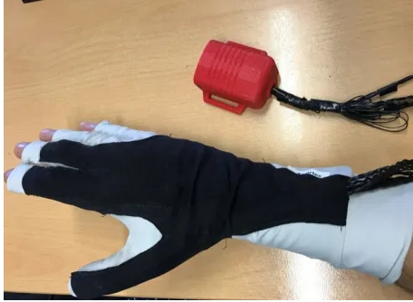
2.1. Sensing glove
64
The sensing glove adopted in this work is made of cotton-lycra and has three textile goniometers
65
directly applied on the top of fabric (Figure 1).
66
67
68
Figure 1. Sensing glove and the wireless acquisition unit.
69
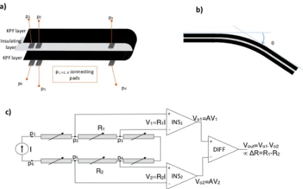
The textile goniometers are double layer angular sensors previously described in [12,13]. The
70
sensing layers are knitted piezoresistive fabrics (KPF) made of 75% electro-conductive yarn and 25%
71
Lycra [14,15]. The two KPF layers are coupled through an electrically-insulating stratum (Figure 2 a).
72
The sensor output is the electrical resistance difference (ΔR) of the two sensing layers that we
73
demonstrated to be proportional to the flexion angle (θ) [12] that is the angle delimited by the
74
76
Figure 2 a) Schematic structure of the KPF goniometer. The black stripes represent the two identical
77
piezoresistive ayers, while the gray stripe is the insulating layer. b) The output (ΔR) is proportional to the
78
bending angle (θ) c) KPF goniometer electrical model and block diagram of the electronics front-end. Two
79
instrumentation amplifiers (INS1 and INS2) and a differential amplifier (DIFF) produce the output ΔV that is
80
proportional to ΔR and thus to Δθ.
81
82
The glove was developed in previous studies to perform daily life monitoring of stroke patients’
83
activity to evaluate the outcome of their rehabilitation treatment [11,16]. In [17] we demonstrated the
84
reliable performance of the glove goniometers, showing errors below 5 degrees compared to an
85
optical motion capture instrument during natural hand opening/closing movements. The glove has
86
two KPF goniometers on the dorsal side of the hand to detect the flexion-extension movement of the
87
metacarpal-phalangelal joints of the index and middle fingers. The third goniometer covers the
88
trapezium-metacarpal and the metacarpal-phalangeal joints of the thumb to detect the thumb
89
opposition. We conceived this minimal sensor configuration as a tradeoff between grasping
90
recognition and wear-ability of the prototype.
91
For the acquisition of ΔR from each of the three goniometers, we designed an ad hoc three-channel
92
analog front-end (Figure 2– c). For each goniometer, the voltages V1=Vp2−Vp3 and V2=Vp5−Vp4 are
93
measured when a constant and known current I is supplied through p1 p6. A high input impedance
94
stage, consisting of two instrumentation amplifiers (INS1 and INS2), measures the voltages across
95
the KPF sensors. These voltages are proportional, through the known current I, to the resistances of
96
the top and bottom layers (R1 and R2). A differential amplifier (DIFF) amplifies the difference
97
between the measured voltages, obtaining the final output ΔV, which is proportional to ΔR and to θ.
98
Each channel was analogically low pass filtered (anti-aliasing, cut-off frequency of 10 Hz). The
99
resulting data were digitally converted (sample time of 100 Sa/s) and wirelessly transmitted to a
100
remote PC for storage and further elaboration.
101
102
2.2. Algorithm for movements detection
103
A HALS operation (Figure 3) has been selected in which the collaborative robot will assist the
104
surgeon. This operation is a cholecystectomy, the surgical removal of the gallbladder. In this case,
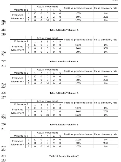
105
the robot will receive the following commands from the surgeon’s hand gestures: center the image of
106
be prepared to uniquely recognize the different movements defined as commands for the robot in
108
order to prevent the robot from performing any undesirable operations.
109
110
111
Figure 3. HALS operation. Photo courtesy ofDr.Martín Parada.
112
113
For the communication during operation with the collaborative robot, a protocol has been
114
established. This protocol will include these three movements that must be detected as commands
115
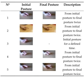
for the robot. The selected movements to be recognized as commands are shown on the Table 1.
116
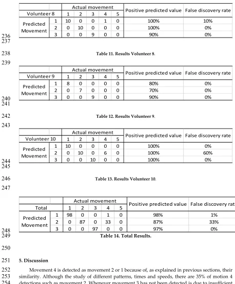
Table 1. Selected movements to be detected.
117
Nº Initial Posture
Final Posture Description Command
1
From initial posture to final
posture twice
To center the image from the
endoscope.
2
From initial posture to final
posture twice.
To indicate a place to suture.
3 -
Initial posture for a defined
time.
To indicate to stretch the
thread.
118
To detect these movements, the developed algorithm analyses the following parameters: flexion
119
pattern, velocity, execution times and value provided by the sensor of each finger. To evaluate these
120
parameters, there is a previous phase in which the variables of each movement in each person are
121
examined. This previous stage is required for each person because the speed and timing of the
122
fingers movement is very variable as shown in figure 4.
123
125
126
127
Figure 4. Sensor values during the same test performed by two different people: a) person 1 and b) person
128
2.
129
Once these variables are defined, the detection algorithm can identify each of the three
130
movements.
131
Motion of each finger is detected by the algorithm for the detection of defined movements that
132
scans the data from the sensing glove searching for the previously defined patterns of each
133
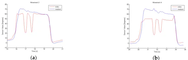
movement. Due to the cross talk between sensors, due to the unique textile substrate in which all the
134
sensors are attached, it may be possible to observe a disturbing signal of a finger when the operator
135
tries to move another, as shown in figure 5. These movements are filtered in order to avoid a
136
misclassification
137
(a) (b)
Figure 5. Sensor values during movement 2 for the same person. There should be no motion in the middle
138
finger because only the index finger should participate.
139
140
Due to the nature of the sensors used, it is possible to determine the degree of flexion that is
141
being applied to the sensor placed on the glove.. However, movement 4 and movement 2 could be
142
mixed up owing to their similarity, as shown in figure 6.
143
(a) (b)
145
(a) (b)
Figure 7. a) Glove data which are proportional to flexion of the finger in movement 1. b)Velocity of
146
fingers involved in movement 1.
147
148
Movement 1 can be identified by analyzing the data of the fingers index and middle. Each rise
149
and fall in the glove values corresponds to the flexion and extension movements of the fingers. This
150
movement consists of a descent (called D1) and ascent (A1) followed by another descent (D2) and
151
ascent (A2), as shown in figure 5. This is the flexion pattern considered for movement 1.
152
The velocity of the fingers involved in this dynamic gesture is higher than the cross-talk ones as
153
shown in figure 7 b). To stablish the typical velocity for this movement, the average and the standard
154
deviation of the velocity along D1 and D2, A1 and A2 are calculated. This typical velocity, V1u, is the
155
minimum value obtained from the subtraction of the standard deviation from the average in three
156
tests performed by the same person. Minimum time during descents, t1Du, (D1 and D2) and ascents,
157
t1Au, (A1 and A2) are also calculated and will represent the characteristic ascent and descent
158
execution times of movement 1.
159
To determine the execution time, t1u, consider the maximum time in which the whole movement
160
is performed; that is D1, A1, D2 and A2.
161
The last parameters to be defined are the maximum, xmax, and minimum, xmin, values of the
162
sensor, which set the thresholds to consider if the obtained values are part of movement 1. They are
163
obtained by analyzing three movement samples from the same person.
164
With these parameters, shown in table 2, movement 1 can be defined and differentiated from
165
others.
166
Table 2. Characterization of defined movements.
167
Mov. Finger Flexion Pattern
Velocity Execution time
D time A time Sensor value
1 Index
Middle D1 A1 D2 A2 |Ve|> V1u te < t1u tD > t1Du tA>t1Au xmin < x < xmax 2 Index D1 A1 D2 A2 |Ve|> V2u te < t2u tD > t1Du tA>t1Au xmin < x < xmax
3 Index
Middle - - te > t3u - - xmin < x < xmax
168
Using the graphs obtained during the performance of movement 2, figure 8, we can conclude
169
that to define it we need to determine the movements of the index and middle finger. The flexion
170
pattern for this movement is D1 A1 D2 and A2 for index finger and no movement for finger middle.
171
The velocity, time of execution, minimum time during descents (D1 and D2) and ascents (A1 and
172
(a) (b)
Figure 8. a) Glove data which are proportional to flexion of the finger in movement 2. b)Velocity of
174
fingers involved in movement 2.
175
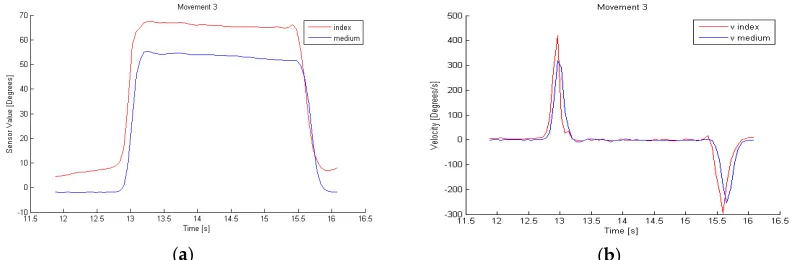
(a) (b)
Figure 9. a) Glove data which are proportional to flexion of the finger in movement 3. b)Velocity of
176
fingers involved in movement 3.
177
178
Movement 3, in figure 9, differs from the other two by the fact that the velocity must be 0, so it is
179
a static position maintained for a certain time. To identify it, we examine the values of the index and
180
middle finger sensors, whose values will be proportional to the flexion carried out by the sensorized
181
finger.
182
The algorithm for the detection of defined movements evaluates all the above mentioned
183
parameters and detects when one of these movements is executed.
184
185
3. Experiments
186
The test consists on carrying out the movements shown in table 3 in the same order, performing
187
a flat position between them. The test has been conducted by 10 people 10 times. Movements 1, 2
188
and 3 are selected to be detected by the algorithm while movements 4 and 5 are introduced to prove
189
that they are not detected as the three selected ones. The two new introduced motions are similar to
190
movements 1 and 2 but there are small differences between them.
191
The characteristic parameters of each movement are calculated from three tests performed by
192
the same person. These parameters are characteristic of each person, so 10 sets of patterns have been
193
obtained for each type of movement, one per person.
194
Table 3. Set of movements.
198
Nº Initial Posture
Final Posture Description
1
From initial posture to final
posture twice
2
From initial posture to final
posture twice.
3 -
Initial posture for a defined
time.
4
From initial posture to final
posture twice.
5
From initial posture to final
posture twice. .
199
4. Results
200
As shown in table 14, movements 1, 2 and 3 must be detected by the algorithm while
201
movements 4 and 5 should not be classified as selected motion. Movement 1 is detected between
202
80% and 100% (98% on overage) and movement 4 is identified as movement 1 only 1%, while
203
movement 2 is detected between 70% and 100% (87%) and movement 4 is recognized as 2 33%.
204
Movement 5 is never mistaken with other movements. Movement 3 is detected between 90% and
205
100% (97%).
206
207
1 2 3 4 5
1 10 0 0 0 0 100% 0%
2 0 8 0 0 0 80% 0%
3 0 0 10 0 0 100% 0%
Actual movement
Positive predicted value False discovery rate Volunteer 1
Predicted Movement
208
209
Table 4. Results Volunteer 1.
210
211
1 2 3 4 5
1 10 0 0 0 0 100% 0%
2 0 10 0 2 0 100% 20%
3 0 0 10 0 0 100% 0%
Actual movement
Positive predicted value False discovery rate Volunteer 2
Predicted Movement
212
213
Table 5. Results Volunteer 2.
214
1 2 3 4 5
1 10 0 0 0 0 100% 0%
2 0 8 0 2 0 80% 20%
3 0 0 10 0 0 100% 0%
Actual movement
Positive predicted value False discovery rate Volunteer 3
Predicted Movement
216
217
Table 6. Results Volunteer 3.
218
219
1 2 3 4 5
1 10 0 0 0 0 100% 0%
2 0 9 0 5 0 90% 50%
3 0 0 9 0 0 90% 0%
Actual movement
Positive predicted value False discovery rate Volunteer 4
Predicted Movement
220
221
Table 7. Results Volunteer 4.
222
223
1 2 3 4 5
1 10 0 0 0 0 100% 0%
2 0 9 0 2 0 90% 20%
3 0 0 10 0 0 100% 0%
Actual movement
Positive predicted value False discovery rate Volunteer 5
Predicted Movement
224
225
Table 8. Results Volunteer 5.
226
227
1 2 3 4 5
1 10 0 0 0 0 100% 0%
2 0 8 0 7 0 80% 70%
3 0 0 10 0 0 100% 0%
Actual movement
Positive predicted value False discovery rate Volunteer 6
Predicted Movement
228
229
Table 9. Results Volunteer 6.
230
231
1 2 3 4 5
1 10 0 0 0 0 100% 0%
2 0 8 0 9 0 80% 90%
3 0 0 10 0 0 100% 0%
Actual movement
Positive predicted value False discovery rate Volunteer 7
Predicted Movement
232
233
Table 10. Results Volunteer 7.
234
1 2 3 4 5
1 10 0 0 1 0 100% 10%
2 0 10 0 0 0 100% 0%
3 0 0 9 0 0 90% 0%
Actual movement
Positive predicted value False discovery rate Volunteer 8
Predicted Movement
236
237
Table 11. Results Volunteer 8.
238
239
1 2 3 4 5
1 8 0 0 0 0 80% 0%
2 0 7 0 0 0 70% 0%
3 0 0 9 0 0 90% 0%
Actual movement
Positive predicted value False discovery rate Volunteer 9
Predicted Movement
240
241
Table 12. Results Volunteer 9.
242
243
1 2 3 4 5
1 10 0 0 0 0 100% 0%
2 0 10 0 6 0 100% 60%
3 0 0 10 0 0 100% 0%
Actual movement
Positive predicted value False discovery rate Volunteer 10
Predicted Movement
244
245
Table 13. Results Volunteer 10.
246
247
1 2 3 4 5
1 98 0 0 1 0 98% 1%
2 0 87 0 33 0 87% 33%
3 0 0 97 0 0 97% 0%
Actual movement
Positive predicted value False discovery rate Total
Predicted Movement
248
Table 14. Total Results.
249
250
5. Discussion
251
Movement 4 is detected as movement 2 or 1 because of, as explained in previous sections, their
252
similarity. Although the study of different patterns, times and speeds, there are 35% of motion 4
253
detections such as movement 2. Whenever movement 3 has not been detected is due to insufficient
254
time in the static position. This situation would not appear during an operation because the surgeon
255
would wait in the static position until the robot would assist him/her so these non-identifications
256
would not be present.
257
Reviewing the results, it can be concluded that the effectiveness of the algorithm depends
258
largely on the person performing the test. This is because not all people have the same ability to
259
perform the exact motion with a high repeatability. Results with surgeons are expected to be better
260
because they have greater skills in this field. Tests have shown that the newly developed algorithm
261
can reliably identify the three movements defined in a series of different continuous movements.
262
pose, but also on intermediate positions and speeds that are continuously analyzed to determine if
264
their pattern is analogous to the model. Different filters are also introduced to make the dynamic
265
gesture recognition algorithm more reliable. The patterns obtained with the sensing glove present
266
sufficient information to be robustly identified preventing failures in those cases where the positions
267
are similar to those of the model but the execution speed of the movement is different.
268
One of the purposes of this study was to test the validity of our non-specific glove to
269
demonstrate the possibility to employ this kind of devices and define the specification for a
270
HALS-dedicated textile glove to be employed in future studies. In future works, glove-based hand
271
motion sensing could be fused with other sensing modalities, such as artificial vison, to make the
272
system more robust.
273
274
6. Conclusions
275
This paper presents a methodology for movement recognition for a textile-based sensing glove
276
in hand assisted laparoscopic surgery. The glove, using piezoresistive sensors, capture continuously
277
the flexion degree of the surgeon's fingers. However, hand movement recognition is not an easy task
278
due to the high variability in the motion patterns in different people and situations. We propose to
279
analyze the data detected by the sensing glove using the methodology described. First, the patterns
280
of the different selected movements are defined. Afterwards, and for each person, the parameters of
281
their movements are identified and then used to identify them online. Taking into account the
282
results in the conducted tests, the methodology has shown to be robust in identifying the set of
283
movements studied to be commands for the collaborative robot.
284
285
Acknowledgments: This research has been partially funded by the Spanish State Secretariat for Research,
286
Development and Innovation, through project DPI2013-47196-C3-3-R.
287
Author Contributions: Alessandro Tognetti and Nicola Carbonaro conceived and designed the sensing glove.
288
Lidia Santos carried out experiments. Lidia Santos processed and analyzed the data. Eusebio de la Fuente, José
289
Luis González, Alessandro Tognetti and Nicola Carbonaro gave advises and discussions. Lidia Santos,
290
Alessandro Tognetti and Nicola Carbonaro wrote the paper. Juan Carlos Fraile, Javier Turiel, Alessandro
291
Tognetti and Nicola Carbonaro supervised the entire work.
292
Conflicts of Interest: The authors declare no conflict of interest
293
References
294
1. LaRose, D.; Taylor, R. H.; Funda, J.; Eldridge, B.; Gomory, S.; Talamini, M.; Kavoussi, L.; Anderson, J.;
295
Gruben, K. A Telerobotic Assistant for Laparoscopic Surgery. IEEE Eng. Med. Biol. Mag.1995, 14, 279–288.
296
2. Bauzano, E.; Garcia-Morales, I.; del Saz-Orozco, P.; Fraile, J. C.; Muñoz, V. F. A minimally invasive surgery
297
robotic assistant for HALS-SILS techniques. Comput. Methods Programs Biomed.2013, 112, 272–283.
298
3. Kim, K. Y.; Song, H. S.; Suh, J. W.; Lee, J. J. A novel surgical manipulator with workspace-conversion ability
299
for telesurgery. IEEE/ASME Trans. Mechatronics2013, 18, 200–211.
300
4. Estebanez, B.; del Saz-Orozco, P.; García-Morales, I.; Muñoz, V. F. Interfaz multimodal para un asistente
301
robótico quirúrgico: uso de reconocimiento de maniobras quirúrgicas. Rev. Iberoam. Automática e Informática Ind.
302
RIAI2011, 8, 24–34.
303
5. Lu, Z.; Chen, X.; Li, Q.; Zhang, X.; Zhou, P. A hand gesture recognition framework and wearable
304
gesture-based interaction prototype for mobile devices. IEEE Trans. Human-Machine Syst.2014, 44, 293–299.
305
6. Song, Y.; Davis, R. Continuous body and hand gesture recognition for natural human-computer interaction.
306
IJCAI Int. Jt. Conf. Artif. Intell.2015, 2015–Janua, 4212–4216.
307
7. Ganokratanaa, T.; Pumrin, S. The vision-based hand gesture recognition using blob analysis. 2nd Jt. Int. Conf.
308
8. Asadi-Aghbolaghi, M.; Clapes, A.; Bellantonio, M.; Escalante, H. J.; Ponce-Lopez, V.; Baro, X.; Guyon, I.;
310
Kasaei, S.; Escalera, S. A Survey on Deep Learning Based Approaches for Action and Gesture Recognition in
311
Image Sequences. 2017 12th IEEE Int. Conf. Autom. Face Gesture Recognit. (FG 2017)2017, 476–483.
312
9. Alon, J.; Athitsos, V.; Yuan, Q.; Sclaroff, S. Simultaneous localization and recognition of dynamic hand
313
gestures. Appl. Comput. Vision, 2005. WACV/MOTIONS’05 Vol. 1. Seventh IEEE Work.2005, 2, 254–260.
314
10. Suryanarayan, P.; Subramanian, A.; Mandalapu, D. Dynamic hand pose recognition using depth data. Proc. -
315
Int. Conf. Pattern Recognit.2010, 3105–3108.
316
11. Lorussi, F.; Carbonaro, N.; De Rossi, D.; Paradiso, R.; Veltink, P.; Tognetti, A. Wearable Textile Platform for
317
Assessing Stroke Patient Treatment in Daily Life Conditions. Front. Bioeng. Biotechnol.2016, 4.
318
12. Tognetti, A.; Lorussi, F.; Mura, G.; Carbonaro, N.; Pacelli, M.; Paradiso, R.; Rossi, D. New generation of
319
wearable goniometers for motion capture systems. J. Neuroeng. Rehabil.2014, 11, 56.
320
13. Tognetti, A.; Lorussi, F.; Carbonaro, N.; de Rossi, D. Wearable goniometer and accelerometer sensory fusion
321
for knee joint angle measurement in daily life. Sensors (Switzerland)2015, 15, 28435–28455.
322
14. Pacelli, M.; Caldani, L.; Paradiso, R. Performances evaluation of piezoresistive fabric sensors as function of
323
yarn structure. Conf. Proc. ... Annu. Int. Conf. IEEE Eng. Med. Biol. Soc. IEEE Eng. Med. Biol. Soc. Annu. Conf.2013,
324
2013, 6502–6505.
325
15. Pacelli, M.; Caldani, L.; Paradiso, R. Textile piezoresistive sensors for biomechanical variables monitoring.
326
Annu. Int. Conf. IEEE Eng. Med. Biol. - Proc.2006, 5358–5361.
327
16. Tognetti, A.; Lorussi, F.; Carbonaro, N.; De Rossi, D.; De Toma, G.; Mancuso, C.; Paradiso, R.; Luinge, H.;
328
Reenalda, J.; Droog, E.; Veltink, P. H. Daily-life monitoring of stroke survivors motor performance: The
329
INTERACTION sensing system. 2014 36th Annu. Int. Conf. IEEE Eng. Med. Biol. Soc. EMBC 20142014, 4099–4102.
330
17. Carbonaro, N.; Mura, G. D.; Lorussi, F.; Paradiso, R.; De Rossi, D.; Tognetti, A. Exploiting wearable
331
goniometer technology for motion sensing gloves. IEEE J. Biomed. Heal. Informatics2014, 18, 1788–1795.
332