[Ginnoriya * et al., 5(9): September, 2018]
ISSN: 2349-5197
Impact Factor: 3.765
I
NTERNATIONAL
J
OURNAL OF
R
ESEARCH
S
CIENCE &
M
ANAGEMENT
SPEED CONTROL OF 3 PHASE INDUCTION MOTOR DRIVE USING SPACE
VECTOR PWM
Gyan Singh Ginnoriya*1 & Sanjeev Jarariya2
*1&2Corporate Insitute of Science & Technology, Bhopal M.P.- 462021
DOI: 10.5281/zenodo.1422342
Abstract
In this paper the speed of an induction motor can be controlled by varying input Voltage or frequency or both. Variable voltage and variable frequency for Adjustable Speed Drives (ASD) is consistently obtained from a three-phase Voltage Source Inverter. Voltage and frequency of inverter can be simply controlled by using PWM techniques, which is a very important aspect in the application of ASDs. A number of PWM techniques are there to obtain variable voltage and variable frequency supply such as PWM, SPWM, SVPWM to name a not many along with the various modulation strategies SVPWM is one of the mainly efficient techniques as it has enhanced performance and output voltage is comparable to sinusoidal. The analysis involves the relationship between modulation signals and space vectors and the switching patterns of space-vector modulation and the trigger of power electronic device.
Introduction
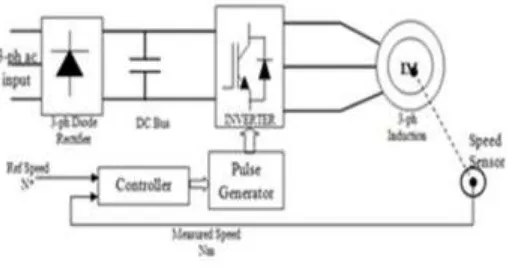
An adjustable speed drive (ASD) is a device used to give continuous variety of speed control. An ASD is competent of adjusting mutually speed and torque from a synchronous or induction motor. An electric adjustable speed drive is an electrical system used to manage motor speed. ASDs might be referred to by a multiplicity of names, such as variable frequency inverters, adjustable frequency drives or variable speed drives. The two terms variable frequency inverters or adjustable frequency drives will only be used to refer to definite AC systems, as is frequently the practice, although some DC drives are also based on the principle of adjustable frequency (Switching frequency of chopper switch).
Figure 1: ASD Block Diagram
[Ginnoriya * et al., 5(9): September, 2018]
ISSN: 2349-5197
Impact Factor: 3.765
I
NTERNATIONAL
J
OURNAL OF
R
ESEARCH
S
CIENCE &
M
ANAGEMENT
Pulse width modulation (pwm)
Variable voltage and frequency supply for Adjustable Speed Drives (ASD) is invariably obtained from a three-phase VSI. In power electronics, converters and motors, the PWM technique is mostly used to supply AC current to the load by converting the DC current and it appears as a AC signal at load or can control the speed of motors that run at high speed or low. The duty cycle of a PWM signal varies through analog components, a digital microcontroller or PWM integrated circuits.
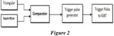
Figure 2
Figure 2 shows the comparator gets the inputs as reference waveform (square wave) and a carrier wave (triangular wave) is supply to the comparator to obtained PWM waveform. Triangular wave is formed by op-amp driver. Triggering pulses are produced at the instant of the carrier signal magnitude is greater then the reference signal magnitude.To turn-on the IGBT switches, firing pulses are produced, the output voltage during the interval triangular voltage wave stipulated the square modulating wave.
Advantages of PWM technique:
Output voltage can be controlled without other components.
Output voltage can be controlled, lower order harmonics can be eliminated and filtering out higher order harmonics by this filter requirements is minimized.
Disadvantages of PWM technique:
The inverter switches are costly as they must have low turn off and turn on times.
Space vector-pulse pwm (SVPWM)
It is an algorithm for the control of pulse width modulation (PWM). SVPWM is used for producing of alternating current (AC) waveforms. It is frequently used to drive 3-phase AC powered motors at variable speed from DC power. Various variations of SVPWM that result in different quality and computational requirements. The development is in the reduction of total harmonic distortion (THD) created by the rapid switching inherent to these algorithms.
Space vector modulation is a PWM regulator algorithm for multi-phase AC generation. The reference signal is sampled frequently, after each sample, non-zero active switching vectors adjacent to the reference vector and one or more of the zero switching vectors are preferred for the suitable fraction of the sampling period in order to integrate the reference signal as the average of the used vectors.
Principle of Space Vector PWM:
[Ginnoriya * et al., 5(9): September, 2018]
ISSN: 2349-5197
Impact Factor: 3.765
I
NTERNATIONAL
J
OURNAL OF
R
ESEARCH
S
CIENCE &
M
ANAGEMENT
Figure 3: Three-phase voltage source PWM Inverter
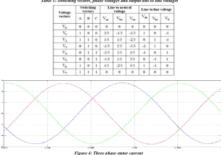
Therefore, the ON and OFF states of the upper IGBTs S1, S3 and S5 can be used to determine the output voltage.
The relationship between the switching variable vector and the line-to-line voltage vector is given by in the following:
The major advantage of SVPWM method is from the fact that there is a degree of freedom of space vector placement in a switching cycle. This improves the harmonic performance of this method.
[Ginnoriya * et al., 5(9): September, 2018]
ISSN: 2349-5197
Impact Factor: 3.765
I
NTERNATIONAL
J
OURNAL OF
R
ESEARCH
S
CIENCE &
M
ANAGEMENT
[Ginnoriya * et al., 5(9): September, 2018]
ISSN: 2349-5197
Impact Factor: 3.765
I
NTERNATIONAL
J
OURNAL OF
R
ESEARCH
S
CIENCE &
M
ANAGEMENT
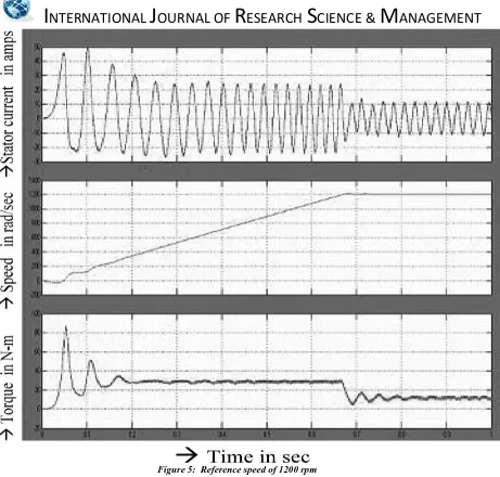
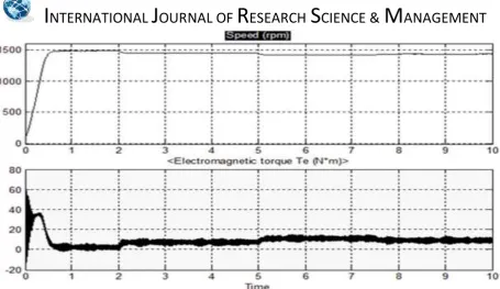
Figure 6: Motor Speed and Electromagnetic torque.
Conclusion and future trends
The Z-source converter overcomes the conceptual and theoretical boundaries and barriers of the conventional current-source converter and voltage-source converter and provides an advanced power conversion idea. The Z-source inverter system can create an output voltage greater than the dc input voltage by controlling the shoot-through duty ratio, which is unfeasible for the conventional ASD systems. In this work, described the operating principle, analyzed the circuit characteristics, and demonstrated its concept and superiority. Different PWM techniques and their comparison are presented. Maximum constant boost control method is additional beneficial PWM control method among the further PWM control methods. Maximum constant boost with 3rd harmonic
injection PWM control method increases output voltage boost while minimizing voltage stresses transversely switching devices. It allows over-modulation wherever modulation index can be varied from 0.50 to 1.150. Z-Source inverter fed IM drive system is simulated using Simulink software using above described PWM method. Results of simulation are compared with traditional PWM inverter. Following results are observed,
1. Shoot-through state is permissible by switching on every devices in the main inverter, thus EMI noise does not involve operation of Z-source inverter. This shoot-through state does not allowed in conventional inverter.
2. The low frequency ripples in the inductor current and capacitor voltage are eliminated completely. 3. Output voltage can be boosted to any desired value by varying shoot-through period T0, in zero states
without changing active state for a fixed modulation index.
4. Shoot-through state is determined by two straight lines, so it is easier to maintain constant shoot-through state and hence the boost factor for all the time.
5. Constituent size (L & C) and hence cost required is less as compared to traditional PWM inverter. 6. Stator current is smooth as compared with traditional PWM inverter. Small permissible ripples in stator
current are observed at lower carrier frequency and at higher carrier frequency very smooth stator current is observed.
[Ginnoriya * et al., 5(9): September, 2018]
ISSN: 2349-5197
Impact Factor: 3.765
I
NTERNATIONAL
J
OURNAL OF
R
ESEARCH
S
CIENCE &
M
ANAGEMENT
References
[1] International Journal of Computer and Electrical Engineering, Vol. 1, No. 1, April 2009 1793-8198 Space Vector Pulse Width Modulation Based Speed Control of Induction Motor using Fuzzy PI Controller R. Arulmozhiyal, Member, IEEE, K. Baskaran, Member, IEEE.
[2] Miaosen Shen, Jin Wang, Alan Joseph, Fang Zheng Peng, Leon M. Tolbert, and Donald J. adams, “Constant Boost Control of the Z-Source Inverter to Minimize Current Ripple and Voltage Stress”, IEEE Transactions on industry application vol. 42, no. 3, May/June 2006
[3] S. Rajakaruna, Member, IEEE and Y. R. L. Jayawickrama, “Designing Impedance Network of Z-Source Inverters” IEEE Transactions on industry application.
[4] G. Pandian and S. Rama Reddy, “Embedded Controlled Z Source Inverter Fed Induction Motor Drive” IEEE transaction on industrial application, vol.32, no.2, May/June 2010.
[5] K. Srinivasan and Dr. S. S. Das, “Performance Analysis of a Reduced Switch Z-Source Inverter fed IM Drives”, Journal of Power Electronics, Vol. 12, No. 2, May/June 2010.
[6] Omar Ellabban, Joeri Van Mierlo and Philippe Lataire, “Comparison between Different PWM Control Methods for Different ZSource Inverter Topologies” IEEE Transactions on industry application, May/June 2010
[7] K.Niraimathy, S.Krithiga, “A New Adjustable-Speed Drives (ASD) System Based On High-Performance Z-Source Inverter”, 978-1-61284-379-7/11 2011 IEEE, 2011 1st International Conference on Electrical Energy Systems
[8] Muhammad H. Rashid, “Power Electronics”, Second Edition, Pearson Education.
[9] C.-G. Kim, J.-H.Lee, H.-W.Kim, and M.-J.Youn, “Study on maximum torque generation for sensor less controlled brushless DC motor with trapezoidal back ELECTRO MOTIVE FORCE,” IEE Proc.-Electro. Power Appl., vol. 152, no. 2, pp. 277–291, Mar. 2005.
[10] J. H. Song and I. Choy, “Commutation torque ripple reduction in brushless dc motor drives using a single dc current sensor,” IEEE Trans. Power Electron., vol. 19, no. 2, pp. 312–319, Mar. 2004.
[11] S. Wu, Y. Li, X. Miao, “Comparison of Signal Injection Methods for sensor less control of PMSM at Very Low Speeds”, IEEE Power Electronics Specialists Conference, PESC 2007, June 2007 pp. 568 – 573.
[12] M. Eskola, H. Tuusa, “Sensor less Control of Salient Pole PMSM Using a Low –Frequency Signal Injection”, European Conference on Power Electronics and Applications, Sept. 2005, pp. 1- 10
[13] S. Ogasawara, H. Akagi, “An Approach to Real-Time Position Estimation at Zero and Low Speed for a PM Motor Based on Saliency”, IEEE Transactions on Industry Applications, Vol. 34, No. 1, Jan./Feb 1998, pp. 163-168
[14] JoohnSheok Kim, Seung Ki Sul, “New Stand-Still Position Detection Strategy for PMSM Drive without Rotational Transducers”, Conference Proceedings of the Ninth Annual Applied Power Electronics Conference and Exposition, APEC '94., Vol. 1, 13-17 Feb. 1994, pp.363 – 369
[15] US Patent No.4654566, “ Control system, method of operating an electronically commutated motor, and laundering apparatus,” granted to GE.
[16] T.Endo, F.Tajima, et al., “Microcomputer Controlled Brushless Motor without a Shaft Mounted Position Sensor,” IPEC-Tokyo, 1983.
[17] K.Rajashekara, A. Kawamura, and K. Matsuse, “Sensorless Control of AC Motor Drives,” IEEE Press, 1996.
[18] S.Ogasawara and H.Akagi, “ An Approach tp Position Sensorless Drive for Brushless dc Motors,” IEEE Trans. on IA, Vol.27, No.5, Sept/Oct. 1991.
[19] US Patent 5859520, “Control of a Brushless Motor,”granted to STMicroelectronics.
[20] STMicroelectronics Application Note AN1130, “An Introduction to Sensorless Brushless DC Motor Drive Applications with the ST72141,” website www.st.com