National Conference on Advances in Engineering and Applied Science (NCAEAS) 29th January 2018
Organized by : Anjuman College of Engineering and Technology (ACET) Nagpur, Maharashtra, India, In association with
International Journal of Scientific Research in Science and Technology
Simulation and Controller Design of an Interline Power Flow
Controller in MATLAB
Saurabh Bodele, Mohammad Aamir, Pratik Raut, Shivam Nasre, Aarti Rao, Sneha Ladse, Prof.Pramod gadge, Prof.Yasmin Sayeed
Electrical and Power, RTMNU, ACET, Nagpur, Maharashtra, India
ABSTRACT
An Interline Power Flow Controller (IPFC) is basically a FACTS controller which finds its utility in series compensation supplemented with power flow control within the transmission line. It contains a minimum two Voltage Source Converters (VSCs) with a common dc-link. In this work we propose to develop a control scheme of an IPFC system with two VSCs to compensate the impedances of two similarly dimensioned parallel transmission lines . The model is simulated using MATLAB Simulink to demonstrate the system behavior of the IPFC.
Keywords : FACTS controller, Interline Power Flow Controller, MATLAB Simulink, STATCOM, SSSC
I.
INTRODUCTION
Voltage or Current Source convertor based Flexible AC Transmission Systems (FACTS can be used to control steady-state as well as dynamic/transient performance of the power system. Such Converter-based FACTS controllers provide an advantage of generating/absorbing reactive power without the use of ac capacitors and reactors supplemented with control of active and reactive power flow in the system[1].
Series connected converter-based FACTS controllers include Static Synchronous Series Compensator (SSSC), Unified Power Flow Controller (UPFC), and Interline Power Flow Controller (IPFC). A SSSC is a series compensator with ability to operate in capacitive/inductive modes to improve system stability [3,4]. The UPFC includes a Static Synchronous compensator
(STATCOM) and a SSSC that share a common dc-link.
The IPFC consists of two or more SSSC with a common dc-link. They provide independent control of reactive power of each individual line, while active power could be transferred via the dc-link between the compensated lines and can also be used to equalize active/ reactive power between transmission lines.
This paper presents models of the IPFC which are based on [1,2]. In section II the methodology is discussed followed by the control scheme in section III. Section IV presents the results.
II.
METHODOLOGY
A. Power Circuit
- with controllable amplitude and phase angle - into the power transmission line through a coupling transformer. Each VSC provides series reactive power compensation for an individual line and it can also supply/absorb active power to/from the common dc-link.
Thus, an IPFC has an additional degree of freedom to control active power flow in the power system when compared to a traditional compensator. This capability makes it possible to transfer power from over- to under-loaded lines, reduce the line resistive voltage drop, and improve the stability of the power system. The coupling transformer primary windings of the master and slave converters are star-connected while their secondary
windings are connected in series with each phase of the transmission line. In addition, the transformer leakage reactance allows regulation of the output voltage magnitude and phase angle, with respect to the transmission line current, and offers stable control of the VSC power output.
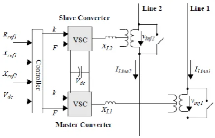
Figure 1 shows the scheme of an IPFC having two VSCs. In this scheme, a master control system is used to compensate both resistive and inductive impedances of the Line 1 power system, and the slave control system is used to regulate the reactance of Line 2 and maintain the common dc-link voltage
B. Converter model
The VSC is the fundamental building block of the IPFC. Various types of pulse-width modulation (PWM) or multi-pulse converters i.e. multi-level converters, are feasible for power conversion.
Irrespective of the VSC topology, a large number of switches must be connected in series to provide the
required valve voltage rating. Therefore, appropriate snubber circuits are used to minimize the switching stresses on each device.
Figure 1. Schematic of an IPFC
We propose to use 3-level Neutral Point Clamped (NPC) PWM VSC. This topology is suitable for high power applications and, when compared to a 2-level topology, it produces fewer harmonics, has smaller dc capacitors, lower switch blocking voltages and lower switching losses.The drawbacks, however, of the 3-level NPC topology are: requirement for a large number of switches, different duties for semiconductors switches and a requirement for balancing the dc capacitor voltages. For the converter model, a 3-phase 3-level NPC VSC with a switching frequency of 900 Hz is used. Each converter consists of 12 valves and 2 dc capacitors C1 and C2. Each valve consists of a switch with turn-off capability and an anti-parallel diode.
The diodes ensure bi-directional current flow and, therefore, the converter can operate in either rectifier or inverter modes.
The switch model consists of two snubber circuits to limit dv/dt and di/dt in the VSC switches.
the transmission line current by exactly 90o, depending upon the requirement of the reactive power.
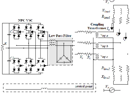
Figure 2. Schematic of 3-level Neutral Point Clamped VSC
The neutral point of the coupling transformer and dclink of the slave system VSC are connected with a large inductor Lo. This path is employed to equalize the dc capacitor voltages of the VSC. However, the master converter system of the IPFC (that regulates the resistive and inductive impedances of the transmission line) has no such connection between the neutral of the coupling transformer and dc-link of the IPFC (Figure 2). Since the output voltage of the VSC contains high-order harmonic components, low-pass and tuned filters are used to provide a clean sinusoidal waveform in both master/slave systems.
III.
CONTROL SCHEME OF IPFC
The IPFC is designed to maintain the impedance characteristic of the two transmission lines. The IPFC consists of two converter systems:
(a) a master converter system that is capable of regulating both resistive and inductive impedances of Line 1; and,
(b) a slave converter system that regulates Line 2 reactance and keeps the common dc-link voltage of
the VSC at a desired level. So, each VSC is independently controllable.
Balancing the dc voltages Vdc1 and Vdc2 on the capacitors C1 and C2 respectively, is an important concern in multi-level converters (Figure 2). Uneven voltage charging on the capacitors can cause over-voltages on the switching devices and that could be destructive for them. The problem may be solved by either
(a) a modified PWM switching pattern [11],
(b) by a voltage regulator for each level using an additional charge balancing leg [12],
or (c) separate dc sources. In order to maintain an equal voltage in the dc-side, the voltage of the neutral point must be regulated.
Here, based on [15], the zero sequence current i0 is used to equalize voltages on the dc-link capacitors of the VSC.
C. Reference Wave Generator (RWG)
The 3-phase transmission line currents are used as the reference signals by the controller to generate either lagging or leading voltages by a 90o phase shift with respect to the transmission line current. The output reference waves are synchronized continuously with the original input waveforms (that could be distorted or contain harmonics). This method, when compared to a conventional PLL, has a fast response to any distortion and suffers very little transient delay.
D. PWM Block
This block provides the firing pulses for the 3-level VSC switches
E. Balancing Controller
achieved by connecting the neutral points of the slave system’s coupling transformer and the dc-link
of the IPFC through a large inductor Lo (Figure 2).
IV.
SIMULATION RESULTS
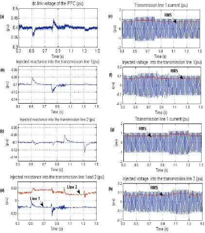
Figure 3. shows the Impact of load variation (a) Dc-link voltage (b) Injected reactance into the Line 1 (c) Injected reactance into the Line 2 (d) Injected resistance into the Lines 1 and 2 (e) Current in Transmission Line
Impact of dc voltage balancing circuit (a) Voltage difference of two dc-link capacitors (b) dc-link voltages Vdc1
and Vdc2 (c) Zero sequence current (d) Net dc-link voltage (Vdc1+Vdc2) (e) Injected reactance into the
System response to step change of the controller reference values (a) Dc-link voltage (b) Injected reactance into the Line 1 (c) Injected reactance into the Line 2 (d) Injected resistance into the Line 1 (e) Injected voltage into the Line 1 (f) Injected voltage into the Line 2 (g) Phase angle between the injected voltage and the transmission line current (h) Receiving-end reactive power in Line 1 and Line 2.
V.
CONCLUSION
We conclude that we will have to develop an IPFC system and will simulate it in MATLAB observe the operation of IPFC.
VI.
REFERENCES
[1]. N. Hingorani and L. Gyugyi, "Understanding FACTS: Concepts and Technology of Flexible AC Transmission Systems," New York, NY: IEEE Press, 2000.
[2]. L. Gyugyi, K.K. Sen, and C.D. Schauder, "The Interline power Flow Controller concept: a new approach to power flow management in transmission systems," IEEE Trans. on Power Delivery, Vol. 14, No. 3, pp. 1115-1123, July 1999.
[3]. V.K. Sood, "Static synchronous series compensator model in EMTP," IEEE Canadian Conference on Electrical and Computer Engineering, Vol. 1, pp. 207-211, Winnipeg, May 2002.
[4]. S.Salem and V.K. Sood, "Modeling of series voltage source converter applications with EMTP-RV," Int. Conference on Power System Transient (IPST'05), Montreal, June 19-23, 2005.
[5]. V. Diez-Valencia, U. D. Annakkage, A. M. Gole, P. Demchenko, and D. Jocobson,
"Interline power Flow Controller concept steady-state operation," IEEE Canadian Conference on Electrical and Computer Engineering, Vol. 1, pp. 280-284, Winnipeg, May 2002.
[6]. J. Chen, T. T. Lie, and D. M. Vilathgamuwa, "Basic control of interline power flow controller," IEEE Power Engineering Society, Vol. 1, pp. 521- 525, Winter 2002.
[7]. D. Menniti, A. Pinnarelli, and N. Sorrentino, "A fuzzy logic controller for Interline Power Flow Controller implemented by ATP-EMTP," IEEE Conf. on Power System Technology, Vol. 3, pp. 1898-1903, Oct. 2002. [8]. B. Faradanesh, and A. Schuff, "Dynamic
studies of the NYS transmission system with the Marcy CSC in the UPFC and IPFC configurations," IEEE Conf. on Transmission and Distribution, Vol.3, pp. 1175 - 1179, Sept. 2003.
[9]. B. Faradanesh, "Optimal utilization, sizing, and steady-state performance comparison of multi-converter VSC-based FACTS controllers," IEEE Trans. on Power Delivery, Vol. 19, No.3, pp. 1321-1327, July 2004. [10]. D. Krug, S. Bernet, and S. Dieckerhoff,