A Novel Multispectral and 2.5D/3D
Image Fusion Camera System for
Enhanced Face Recognition
William Williams
A thesis presented for the degree of
PhD Computer Science and Information
Systems
This report is substantially the result of my own work, expressed in my own words, except where explicitly indicated in the text. I give my permission for it to be submitted to the JISC Plagiarism Detection Service.
The report may be freely copied and distributed provided the source is explicitly acknowl-edged.
Signed:_______________________________ William Williams
Acknowledgement
This thesis would not have been possible without the encouragement, support and guidance of several people to whom I oer my sincere gratitude and thanks. In alphabetical order they are:
Chloe Harrison
Prof. Steve Maybank
Robin Watling
Sue Williams
CONTENTS CONTENTS
Contents
1 Introduction 8
2 Background 10
2.1 Image Fusion . . . 11
2.2 Image Fusion for FR . . . 14
2.3 Adaptive Image Fusion . . . 19
2.4 2.5D/3D Image Fusion . . . 22
2.5 Image Fusion Technology . . . 25
2.6 Summary of the Literature Review . . . 29
3 Design 31 3.1 Camera System . . . 31
3.2 Camera registration . . . 38
3.3 Face Databases . . . 39
3.4 Eyeglasses Compensation . . . 43
3.4.1 Mapping of VIS to LWIR Eye Images . . . 44
3.4.2 Local Geometry Preservation . . . 47
3.4.3 Eyeglass Detection and Segmentation . . . 47
4 Method 52 4.1 Image Fusion in Transform Space . . . 52
4.1.1 Discrete Wavelet Transform (DWT) . . . 53
4.1.2 Contourlet Transform (NSCT) . . . 54
4.1.3 Non-Adaptive Fusion In Transform Space . . . 58
4.1.4 Adaptive Fusion in Transform Space . . . 60
4.2 Discrete Cosine Transform Features . . . 64
4.3 Adaptive Image Fusion in Match-Score Space . . . 68
5 Results 70 5.1 Single Modality Images . . . 72
5.2 Non-adaptive Transform Fusion . . . 79
CONTENTS CONTENTS
5.3.1 Fusion in DWT Space - Energy Measure . . . 81
5.3.2 Fusion in DWT Space - WSML Measure . . . 83
5.3.3 Fusion in DWT Space - Sobel Measure . . . 85
5.3.4 Fusion in NSCT Space - Energy Measure . . . 87
5.3.5 Fusion in NSCT Space - WSML Measure . . . 88
5.3.6 Fusion in NSCT Space - Sobel . . . 89
5.4 Match-Score Fusion . . . 91
5.4.1 Semi-Adaptive Match-Score Fusion . . . 91
5.4.2 Match-Score Fusion of Fused DCT Features and DWT Fused Images . . . 93
5.5 Image Fusion In Feature Space . . . 97
6 Conclusions 101
7 Further Work 104
8 Summary 105
CONTENTS CONTENTS
Abstract
The fusion of images from the visible and long-wave infrared (thermal) portions of the spectrum produces images that have improved face recognition performance under varying lighting condi-tions. This is because long-wave infrared images are the result of emitted, rather than reected, light and are therefore less sensitive to changes in ambient light. Similarly, 3D and 2.5D images have also improved face recognition under varying pose and lighting. The opacity of glass to long-wave infrared light, however, means that the presence of eyeglasses in a face image reduces the recognition performance.
This thesis presents the design and performance evaluation of a novel camera system which is capable of capturing spatially registered visible, near-infrared, long-wave infrared and 2.5D depth video images via a common optical path requiring no spatial registration between sensors beyond scaling for dierences in sensor sizes. Experiments using a range of established face recognition methods and multi-class SVM classiers show that the fused output from our camera system not only outperforms the single modality images for face recognition, but that the adaptive fusion methods used produce consistent increases in recognition accuracy under varying pose, lighting and with the presence of eyeglasses.
1 INTRODUCTION
1 Introduction
This thesis describes the design and development of a novel multispectral camera system which is capable of capturing images in the visible (VIS) near-infrared (NIR) and long-wave infrared (LWIR) spectral bands as well as 2.5D/3D depth data (Section 3.1). To our knowledge, no camera system such as this has been developed and investigated for face recognition applications. Two databases are generated using the camera system (Section 3.3 on page 39) under vary-ing pose, lightvary-ing and eyeglasses. The results of extensive face recognition experiments across multiple image fusion and recognition methods are reported. The experiments explore the per-formance of the fused output versus single-modality images and attempt to identify an optimum method for automatic, adaptive image fusion (Section 5.3). An eyeglasses-compensation algo-rithm which automatically detects and synthesises areas occluded by eyeglasses in the LWIR images using information from the VIS images (Section 3.4) is also applied and the results reported in Section 5.1.
This thesis demonstrates that a manually weighted fusion technique yields improved face recognition under varied lighting conditions for a particular set of images, but that a specic set of fusion weights cannot necessarily be applied universally under any variation in lighting. We will show that in such cases, what is commonly achieved is a set of weights suitable only for a particular set of face images. Images fused using more adaptive methods produce more accurate face recognition under varied pose, lighting and with eyeglasses.
We demonstrate that images which are adaptively fused in the transform and feature spaces can be further fused with single modality images in match-score space to improve recognition accuracy and also produce more consistent recognition performance under changing lighting conditions. A method of match-score fusion using the transform fused images and feature fused images is shown to achieve higher recognition and verication rates than methods based on single modalities for all lighting modes used across a range of established face recognition methods.
Finally a feature fusion method utilising the adaptive transform fused image and fused features is described and tested using multiclass SVM classiers. The feature vector is shown
1 INTRODUCTION to give a highly consistent 98% and 94% recognition rate for both lighting modes used in our experiments. From this we conclude that a multispectral camera system using an adaptive fusion algorithm in the transform and feature spaces is an eective solution to face recognition under realistic or poor lighting conditions and varying pose.
2 BACKGROUND
2 Background
There are several areas of research which are relevant to this thesis. These can be subdivided as:
Image fusion: the fusion of information from two or more images in order to produce a single image that is of greater use to an image processing task than the constituent images. Image fusion for face recognition: the application of image fusion specically to face images
for the purpose of recognition and verication.
Adaptive image fusion: a method of image fusion whereby the information in the stituent images is selected for fusion by a process which adapts to variations in the con-stituent images.
2.5D/3D and multi-modal image fusion for face recognition: the fusion of images with data captured using depth sensors and other 2D images for application to face recognition and verication.
Image fusion technology: camera systems and hardware designed for the capture and fusion of images.
A literature review and discussion of these research areas with regard to this thesis are conducted in sub-sections 2.1 to 2.5 below. A summary of the motivation and contribution of the thesis with regard to the literature review is then given in Section 2.6.
2.1 Image Fusion 2 BACKGROUND
2.1 Image Fusion
Early work in fusing long-wave infrared (LWIR) and visible (VIS) sensor images was started in the late eighties by Burt and Adelson [11] and Toet et al. [84] who used Laplacian (LP) and contrast pyramid (CP) techniques respectively in order to select the important features from the constituent images. While both algorithms are designed to produce output for human observation only, it is interesting to note that, in their advance on Burt and Adelson's work, Toet et al. exploit knowledge of how the human vision system works for their fusion algorithm. This is particularly relevant to ongoing research today, twenty two years later, in cognitive image fusion [82].
Algorithms for image fusion are divided into several categories with regard to abstraction; low, mid and high. The algorithms that have been demonstrated within these categories work at signal, pixel, feature or symbolic levels where signal is at a low level, pixel and feature are mid level and symbolic methods operate at a high level of abstraction. The majority of image fusion algorithms that have been researched and developed work at the pixel level in either the spatial or a transform domain [30, 45].
Image fusion algorithms operating in the spatial domain can be very simply implemented by combining the pixel values of the constituent images using a weighted average for each image [45]. Image fusion algorithms operating in a transform domain can be implemented by applying a multi-resolution transform e.g. wavelets [45, 47] or contrast pyramids [84] and combining the lower resolution images which are produced. The fused image is then obtained by performing the inverse transform.
The initial work with contrast pyramids described in [84] creates a ratio of low pass (ROLP) pyramid for the VIS and LWIR images. By convolving an image with a weighted Gaussian lter, each level of the ROLP pyramid contains a low-pass ltered, subsampled copy of the image from the tier below it. The ratios of the low pass images at each level are then computed before a composite ROLP pyramid is created by selecting the values from the constituent pyramids. The selection criteria can be chosen with respect to the post-processing desired for the nal fused output.
2.1 Image Fusion 2 BACKGROUND
The use of wavelet transform coecients for image fusion has many advantages over ROLP pyramids. They are more compact, can provide directional information and reduce redundancy as each level of resolution does not contain blocking artifacts which are common in pyramid techniques [47].
The simplest and most commonly used wavelet transforms is the Discrete Wavelet Transform (DWT) [31, 47, 56]. This is a multi-resolution transform whereby an image is decomposed into detail and average coecients. The detail coecient images give vertical, horizontal and diagonal edge information. The average coecient image represents a low-pass ltered version of the original image and gives texture information. It has been shown that, when two images from dierent spectral modalities are decomposed using the DWT (with the obvious assumptions that they are the same size and are spatially registered), a single fused image can be created from the two constituent images by selecting or weighting a combination of coecients from either constituent image. The nal fused image is generated by using the Inverse Discrete Wavelet Transform (IDWT).
The DWT method described in [47], while producing a fused image which resulted in im-proved perception by humans, does have shift variant behaviour. This is inherent in most transforms. A shift in the input signal during decomposition can cause the DWT coecients at dierent levels of resolution to change [42, 45, 56]. This can produce "ringing" artifacts as well as problems in preserving edge and texture detail within the fused image.
The Dual-Tree Complex Wavelet Transform (DT-CWT) [42, 66] uses a "dual tree" of low-pass lter banks. The complex wavelet transform (CWT) has improved analytical properties in terms of reduced redundancy and shift invariance compared to the DWT as it uses complex valued scaling functions and complex valued wavelets. In a similar way to the classic Fourier transform (FT) which produces real and imaginary components of a signal (i.e. a pair of cosine and sine components that are 90° out of phase with each other), and therefore a truly analytical signal, in DT-CWT two "trees" of low-pass lter banks are designed to reproduce similar behaviour to the FT in the complex wavelet and complex scaling functions. The main advantages of this method are that it is shift invariant while also being directionally sensitive [42, 56], the
2.1 Image Fusion 2 BACKGROUND latter being particularly useful for detecting edge information within an image. The DT-CWT produces better qualitative and quantitative results than both pyramid and DWT methods when used for image fusion [56] due to the inherent shift invariance. It improves on prior attempts to produce shift invariant techniques (SIDWT) by reducing redundancy. However, it is worth noting that this improvement comes with a higher computational and system resource demand than standard DWT [45].
Not as much work has been done on techniques for image fusion in the feature or symbolic levels as has been done at the pixel level. The majority of feature level methods work by dividing the input images into regions and then applying a priority rule to select which regions from the constituent images are used in the nal fused image. In [45] the detail coecients of the DT-CWT are used to obtain texture information from the constituent image. The gradient function is then applied and combined with intensity information, thus providing information on edge locations where the resulting gradients are largest and allowing the segmentation of the image into regions of interest.
The advantages of such methods are [45, 61] a) the ability to use more intelligent fusion rules when selecting the regions to be fused, b) regions within the fused image can be highlighted by weighting them. The weight can depend on various properties of the region. c) a reduced sensitivity to signal noise d) the possibility of improved image registration by using the region features identied in the constituent images. There is also the suggestion in [45] that future sets of component images could have their fused output rapidly predicted by tracking the movements of the image regions. This is particularly relevant to real-time video surveillance in that it would drastically reduce the computational demand on the system.
The various methods of region-based fusion schemes are discussed in [45]. While more complex than transform domain schemes, the ability of feature-level fusion schemes to apply weightings to regions based on their activity, size or position relative to other regions allows the optimisation of the nal fused image for its intended end use.
2.2 Image Fusion for FR 2 BACKGROUND
2.2 Image Fusion For Face Recognition
Face detection and recognition are increasingly important for security applications [94]. As camera systems and networks produce better quality images, decrease in price and generally become more widespread, the advantages of robust facial recognition systems for identication have become more and more apparent.
As mentioned above, one of the major disadvantages of sensors working in the visible range of the electromagnetic spectrum (~400-750nm) is that they are very sensitive to ambient changes in light. Face detection and identication suer greatly when there is a decrease or shift in light source either due to natural variations (e.g. night time, shadows) or when the viewed scene is indoors and there is shuttering or obscuration of the light source. Further to this the subject's facial expression and pose relative to the camera can also aect the performance of face recognition. Sensors working in the long-wave range (~8-14μm) provide better performance
under ambient light variations [74, 75, 89] as they detect emitted light coming from the subject, rather than light reected o the subject. While LWIR images are in many ways superior to VIS images for face recognition [74] they can also be hindered by external, environmental variables. Indeed, images captured via LWIR sensors can prove problematic since any change in the temperature of the surroundings or the subject will aect the resulting image and therefore the match rate [27, 34]. Temperature changes in the subject are dicult to avoid since they can depend on any combination of metabolic processes within the subject, ambient temperature, alcohol consumption or physical exertion. In addition the presence of eyeglasses also aects the recognition performance, as glass is opaque to LWIR light. This causes eye-glasses to obscure feature information. While occlusions in the image are potentially less detrimental to recognition rates than variations in outdoor or uncontrolled conditions [34], they are obviously still a concern for face recognition applications as ~50% of the population wears some form of eye-glasses.
Due to the advantages and disadvantages of the two sensor modalities it was found that under more realistic experimental conditions i.e. with the subject moving or changing expression or out of alignment with the camera, neither the VIS or LWIR images were superior to the other with regard to face recognition [88]. In an attempt to overcome these limitations the fusion of multispectral face images was found to produce images that provide a higher performance for
2.2 Image Fusion for FR 2 BACKGROUND face recognition than either single modality image on its own. As a result, there has been an increasing amount of research focused on multispectral or multisensor image fusion algorithms that produce an output image optimised for use with various face recognition algorithms [6, 12, 14, 31, 41, 44, 69, 71, 88].
In [31] a DWT fusion method is used to decompose the images into approximation coecients and detail coecients using Haar wavelets, before weighting the coecients and combining them. Finally, the fused image is generated by applying the inverse DWT (IDWT) to the set of fused coecient images. The coecient weights applied during the fusion are determined by the quality of the respective images for face recognition. If, for example, there is a large reduction in light, the VIS image will lose a lot of the information required for face recognition. In this case the weights are adjusted such that the fused coecients are weighted towards the LWIR than the VIS coecients. The optimal values of these weights under dierent lighting conditions are xed and set a priori through experimentation with a particular face image database.
In [31] the xed-weight method applied to the LWIR and VIS images (0.3 and 0.7 respec-tively) was reported to produce a higher success rate for face recognition than simply averaging the DWT coecients (i.e. weights of 0.5 and 0.5) although problems remained when using weighted DWT fusion in the presence of eye glasses. Because LWIR is blocked by glass, eye glasses appear as black ellipses in the LWIR image. This can severely decrease the success rate of any face recognition algorithm applied to the nal fused output image. If the weighting in the nal fused image is in favour of the LWIR image, the success rate may be decreased still further. In [44] a similar fusion method to [31] is used. However, an ellipse tting algorithm is employed to locate and then replace any eye glasses found within the LWIR image with a generic eye template. The template is generated by averaging all the LWIR images with no eyeglasses that are available in the test database. This is shown to produce large improvements in the success rate in the rst match (39% and 33% increases across two databases) and the rst ten matches (16.8% and 6.7% across two databases). However, injecting "non-scene" information is not a desirable solution to the problem of eye glasses in LWIR images as in a real-world environment an ambient temperature change could cause a dierence in the contrast between the replacement eye data and the rest of the face. It is also assumed that a large repository of LWIR images is
2.2 Image Fusion for FR 2 BACKGROUND available for creating the averaged data. Further to this, while it is not explicitly discussed, the ellipse tting, eyeglass removal and eye template superimposition, which requires rotation and resizing of the template may not lend themselves to a real-time application.
An alternative method to weighted averages of the DWT coecients is image-based fusion using some selection criteria to pick the coecients to be used from each constituent image. An example of this method is described in [71] where genetic algorithms (GA's) are used for making the selection of coecients during image fusion. The chromosome in the genetic algorithm is encoded as a bit string, with each bit representing a wavelet coecient in the fused image. The values of these bits are then used to select the image coecient to be used in the nal fused image i.e. 0 = LWIR, 1 =VIS. Once the GA has converged on a solution, the image fusion is completed by applying the optimised chromosome as a binary mask to the VIS and LWIR coecients. The nal fused image is then produced using the IDWT as before.
While genetic algorithms are an interesting approach that provides more variability than static weighted averages and also proves more robust to the presence of eye glasses and ambient light variations, they do present some problems. The inherent problems of GA's are that they a) don't always provide the best coecient selections for fusion and b) have a variable rate of performance depending on the random value used to seed the algorithm.
In [71] a GA is used for fusing face images by rst selecting the parent chromosome and applying it to the LWIR and VIS image coecients. The inverse transform is then applied to the fused coecient image and the nal fused image is passed to a face recognition algorithm which provides a recognition score. The chromosome is then recombined and mutated as per the GA, which gives a new chromosome which, in turn, is used to produce another fused image and recognition score. The recognition scores give a measure of "tness" which allows the GA to identify which chromosome produces fused images with best face recognition performance. The process is then iterated until a convergence criteria is met i.e. a minimum recognition score is achieved. This carries a large computational cost and renders the proposed application of genetic algorithms, in this specic manner, totally unsuitable for real-time image fusion. Further to this, as the chromosome is optimised to a sepcic set of training images there is a risk of overtting
2.2 Image Fusion for FR 2 BACKGROUND the fusion to a particular database.
In [18] a fusion method is proposed using the non-separable wavelet frame transform (NWFT) which is similar to the DT-CWT method discussed above and in [42]. The non-separable wavelet transform (NWT) method treats the image as an area as opposed to rows and columns in DWT. By altering the lter coecients to the NWT (low-pass and high-pass lters), the NWFT is ob-tained. As explained in [42], this means the NWFT is shift invariant and has an improved directional property. However, after the NWFT is obtained, a coecient selection method is still required in order to obtain a nal fused image. In [18], a maximum absolute value rule is applied as the selection criteria. The results showed an above 90% recognition performance for experiments conducted with variations in illumination, eyeglasses and expression. However, the recognition performance was reduced to 84.85% when all three variables were changed simul-taneously. Under the same conditions, a DWT method (using an absolute maximum selection rule) produced a 75.76% recognition performance. When we compare these results to those found in [31] in which weighting the coecient selection of a DWT fusion method produces a recognition performance of 95.84% (improved from 90.31% using an absolute maximum selection rule), it suggests that fusion using the NWFT may not produce particularly large increases in performances compared to other transforms reported in the literature.
Feature-based image fusion uses fusion selections based on features identied within the image [69]. The image fusion algorithm described in [71] eectively treats the selection of these features as a pattern recognition problem in which GA's are employed to nd the optimum set of coecients for fusion. In [69] a post-image fusion process is used whereby a supervised learning method (specically a Support Vector Machine or SVM) is used to select feature vectors from a fused image for face recognition. While it is noted that the initial fusion method using DWT gives a low enough complexity for it to be used in real-time, there is no similar analysis of the complexity of the SVM post-processing stage. This approach to image fusion, when applied to multispectral situations, appears to give the best results when using VIS and near-infrared (NIR) which is reected light. The results from [69] show an error rate of 3.18% when the scheme is applied to VIS and LWIR. In comparison, the results in [31] obtained by fusing weighted DWT coecients, without the computational demand of the secondary feature fusion via SVM, have
2.2 Image Fusion for FR 2 BACKGROUND an error rate of 4.16%.
An alternative to fusing the face images in image or feature space is match-score space fusion whereby the match scores for the images in each spectral modality are calculated separately and the similarity scores from each modality then fused by a weighted average. This has been shown in applications to some mulitspectral image databases to produce better recognition results than image or feature fusion[12]. An example of this method can be seen in [25] where match score fusion is applied to a set of VIS, NIR and LWIR face images using a manually adapted set of score fusion weights to achieve a 95% recognition rate under varying light and expression, although it is worth noting that the face images used had no variation in pose and did not feature eyeglasses. The application of match score fusion to an already fused image set is investigated in [70] whereby the VIS and LWIR image pairs for each subject in a database are rst fused in the wavelet transform domain. Two sets of features, namely the 2D log Polar Gabor and Local Binary Pattern (LBP) features, are then extracted from the fused image set and the recognition algorithm applied before fusing the resulting match scores. It was shown that this hybrid method of image and match score fusion gave a verication rate of 98.08% at a false acceptance rate (FAR) of 0.01% when applied to the Equinox database [70]. It is worth noting, however, that only verication results are reported so no conclusion can be drawn for recognition performance.
2.3 Adaptive Image Fusion 2 BACKGROUND
2.3 Adaptive Image Fusion
Research into image processing using the DWT has shown that the low-pass, average coecients, while being the most suitable for face recognition applications [67, 68] are very sensitive to changes in illumination [55, 67]. In comparison, the highpass detail coecients capture texture and geometric details and are more resilient to changes in illumination, but edge and corner information can still be lost under extreme lighting variations [1] and changes in expression [67]. These variations can be compensated by applying a set of static weights, however image fusion can unintentionally become over-optimised for the particular test database being used. That is to say, the resulting algorithm can fail if the database is changed. The risk of this overtting to a particular database is clear and indeed, it has been found that fusion methods which have previously been reported to perform well under controlled conditions do not do well in uncontrolled or outdoor environments [38]. The aim, therefore, is to nd a method of multispectral image fusion which not only allows accurate face recognition and verication but can do so under widely varying or previously unobserved conditions e.g. lighting,pose, expression. This is identied in the survey literature [38, 97] as a promising area for the future of face recognition .
For an image fusion routine to avoid this overtting it must be, to some extent, adaptive to the type and quality of the component images. Image quality measures have been an active area of image processing research for the last two decades and are well documented in the literature [24, 26, 63, 87]. For the purpose of image fusion, however, the majority of the research has concerned the fusion of images used for surveillance (VIS and NIR images), medical (CT and MRI images) or multi-focus applications. These lend themselves well to image quality measures as there is an a posteriori comparison to be made between the nal fused image and the component images after which the fusion algorithm can be adjusted in order to optimise the output. Obviously for face recognition this post-fusion comparison is not available. We do not know if the fusion of two or more face images has been successful in terms of improved recognition until we compute similarity scores across training and testing sets. In a real-world application the fusion system would not know if a face submitted for verication is valid or an impostor and any attempt to iteratively optimise the fusion based on the resulting verication score risks increasing the rates of false acceptance and false rejection.
2.3 Adaptive Image Fusion 2 BACKGROUND
For face recognition applications, therefore, it would be advantageous to detect any quality problems in the component images and either process them prior to fusion, or adjust the fusion routine to minimise their impact on recognition accuracy. In [68] it is found that if all of the images in a VIS modality face database are normalised by histogram equalisation (HE) prior to performing recognition tests, the recognition accuracy is reduced in many cases. Their research showed that adaptively applying HE only to images of low luminance quality gave improved recognition accuracy. To do this, probe images were measured for a global luminance distortion and HE applied if they were below a threshold.
In [67] a set of VIS face images are processed using the DWT and the sensitivity of dierent subbands to changes in lighting and expression are measured. Having identied that the approx-imation subband provides the most accurate recognition rate under uniform lighting, but the low-highpass (LH) subband is the least sensitive to variations in lighting, a multi-stream recog-nition method is proposed by the authors. The match score for each subband of the probe DWT image is calculated with those in the gallery database and the match scores are weighted and combined. The authors concluded that adaptive fusion weights were necessary to compensate for variations in the probe image lighting.
For non-adaptive image fusion in the transform domain such as DWT, the aim is to preserve the discriminatory features of the approximate (low frequency) and detail (high-frequency) sub-bands while simultaneously minimising the transference of any noise to the nal fused image. For an adaptive image fusion method the aim is to be able to measure and identify a probe image with poor illumination and reduce the weighting of the VIS low frequency coecients in the nal fused image. Similarly for adaptive fusion in the feature and match-score spaces, it would be advantageous to detect any variations in lighting and down-weight the aected features or match scores in order to improve the accuracy of the face recognition.
Recently, the trend for 'deep learning' techniques have been applied to feature extraction for image fusion [49, 95]. The application of a Deep Neural Network (DNN) for this purpose is attractive as the features which minimise the intra-class variability and maximise the inter-class variability are selected automatically by the DNN once. However, a large number of samples
2.3 Adaptive Image Fusion 2 BACKGROUND are required in order to produce a trained network which is capable of generalising. This would require thousands of samples per class i.e. face images per subject, and for our application of multispectral image fusion we are limited by the size of our database (see Section 3.3). There are also recently researched aws within DNNs showing that very small changes in pixel values can change the output classication of a DNN [54, 79].
2.4 2.5D/3D Image Fusion 2 BACKGROUND
2.4 2.5D/3D and Multimodal Image Fusion for Face Recognition
Over the past decade the increasing availability and quality of low-cost depth sensors has ensured the rapid growth of research into the application of 3D information for face recognition [2, 7, 36, 46, 52, 53, 59, 81, 85]. The ability to capture a face image in 3D intuitively suggests a solution to the problem of pose variation and, if the depth sensor used works in the IR, it is also argued that 3D face recognition can be made insensitive to lighting variations [8, 50].The two most common methods for estimating depth are structured light and time-of-ight (TOF). In structured light sensors a known NIR laser pattern is projected onto a scene which is viewed by an NIR camera operating at the same wavelength as the laser. Any object or set of objects in the scene reects the points of the laser pattern back into the NIR camera. If the laser pattern as measured by the NIR camera is known when the pattern is projected onto a at plane at a known distance, then any deformation of the pattern due to an object can be used to estimate depth. Due to the nature of this conguration the pairing of the NIR camera to the NIR laser projector is critical and specic to each structured light sensor. Calibration is carried out at the point of manufacture and built into hardware within the unit.
In contrast, a TOF sensor uses the known speed of light to calculate distances based on the time taken for an emitted photon to be projected into the scene and reected back. In order to do this the TOF sensor has a NIR emitter which emits high frequency pulses of NIR light onto a scene. In order for the NIR camera to discriminate between the probe laser light and other light sources the probe laser is either modulated using a radio frequency (RF) or synced with a high-speed electronic shutter within the NIR camera.
A depth sensor will generally use a single IR wavelength laser source to probe and capture a scene; thus large changes in visible light that cause inaccuracies in VIS face recognition have only a small eect on the depth sensor only. However, to state that that 3D depth sensors are totally insensitive to illumination variations is not accurate.
Most articial light sources emit radiation in the NIR waveband where most depth sen-sors operate. Also, terrestrial sunlight can be considered to be a broad-band from ~300nm to
2.4 2.5D/3D Image Fusion 2 BACKGROUND >2000nm and thus natural light variations will also include the NIR waveband (750-1400nm). While depth sensors do attempt to prevent external noise from interfering, a depth sensor must detect and measure very small changes in a single wavelength of light with a high dynamic range. Thus areas of a subject's face with high reectivity will invariably cause blooms in the detected NIR image, which can translate into inaccurate depth measurements. Indeed in [8] the myth of 3D image illumination invariance is discussed for this very reason.
A modern depth sensor will generally produce depth information in two modalities: a set of 3D points, or point cloud, recorded in a three dimensional array
a 2D intensity image where the gray scale value of each pixel is related to a depth value within a scene. Commonly referred to as a 2.5D, range or depth image.
There has been increasing interest in and, indeed, successful demonstrations of face recognition applied to either the 3D data [2, 46] or 2.5D data [36, 52] alone. However, early research reporting high recognition performances in 3D alone have proved to be too optimistic when the size of the database increased from tens to hundreds of subjects, or when more challenging poses or lighting were used during capture [8, 97]. With most modern depth sensors producing both a 2D colour and depth image, the application of 2D and 2.5D/3D fusion has also been investigated in the research literature. The most common approach has been to apply a recognition algorithm to each modality separately and then apply a match-score fusion [8, 16, 81, 85, 92]. This has been shown to outperform a single modality approach.
There has also been research conducted into face recognition using recovered depth images from multiple 2D cameras, as opposed to a dedicated depth sensor. In [92] a photometric stereo camera system consisting of four cameras is constructed and used to automatically capture face images of subjects as they pass in front. Depth images are reconstructed from the four images and the recognition scores for the 3D and 2D images are fused in match-score space. The results show that the match-score fusion of 2D images with depth images recovered from photometric stereo also produces an increased recognition accuracy compared to using a single modality.
While there has been an increasing interest in the fusion of 2.5D and 3D face data from one depth sensor, comparatively little work as been done on the fusion of 2.5D/3D data with
2.4 2.5D/3D Image Fusion 2 BACKGROUND 2D intensity images captured in VIS, and NIR/LWIR spectral modalities. This is noted in the recent survey literature where the authors conclude:
...the work on 3-D + IR and visual+IR+3-D is comparatively rare. That is mainly because 1) visual images carry face texture information that is particularly useful for face recognition; 2) visual images are easy to acquire and process; 3) no devices currently exist that can capture faces with the three modalities synchronously. [97]
2.5 Image Fusion Technology 2 BACKGROUND
2.5 Image Fusion Technology
There has been a large discrepancy between the extent of research into novel image fusion techniques and viable methods for real-world deployment. This is noted in the image fusion technology review literature:
"...much of the literature to date on the topic of image fusion has not drawn attention to system-level issues or practical matters associated with making a real-time image fusion system a genuine reality, preferring to explore ever more complex or obscure methods of combining pixels."[73]
As sensor technologies have become more compact and cheaper, reliable real-time image fusion systems have recently become viable, although the complexity of the fusion algorithms employed is still limited by the computational resources available [70]. There exists a multitude of papers that, while mathematically interesting, propose fusion algorithms that are too complex to be employed in a real-time scenario, [70, 71]. To this end, when we refer to 'Image Fusion Technology', we are focusing on hardware, software and algorithm design developments that have a real-time system as the primary goal.The various process involved in a generic image fusion system are identied as image registration, image pre-processing, image fusion and image post-processing [73].
Unexpectedly the choice of fusion algorithm used is not the greatest factor aecting the quality of the system's output. The registration of the two images, such that they are spatially matched to one another prior to fusion, has the largest eect with regard to output quality [73]. Indeed, in [40] it was found during comparisons in recognition rates using VIS and LWIR images that the LWIR images were very sensitive to errors in eye-position registration. Further research has shown that it is dicult to reliably identify salient facial features such as eyes in LWIR images [27]. The advantages, therefore, of a multi-spectral camera system with a common optical path are considerable [23, 73] as the registration of the separate modalies is inherent at the point of image capture. This means that the computational demand on the fusion system's resources is massively reduced and a manual registration stage during image fusion is unnecessary.
2.5 Image Fusion Technology 2 BACKGROUND
The initial work in image fusion of LWIR and VIS images in [84] utilised a system that obtained images via two sensors over the same optical path. This was achieved by using a dichroic germanium mirror, or "beam-splitter" at 45° to the incident light. The mirror splits the incoming light into the constituent wavebands relevant to the sensors used. The LWIR sensor is placed in-line with the incident light, behind the germanium dichroic mirror. In this arrangement, the mirror acts as a long wave pass lter for the LWIR sensor. The VIS sensor is placed at 45° to the LWIR sensor, such that it is exposed to the reected, visible-range light from the dichroic mirror. Registration between the two sensors was then carried out by placing an array of lights within the scene and adjusting the camera optics in order to "overlay" the lights in the component images.
Germanium, whilst having a relatively low transmittance (T%) of ~45% in the range of 2-12µm still provides enough light in the appropriate wavebands to produce an image in the LWIR sensor, however the signal is reduced and the resulting images are of rather poor quality. The LWIR sensor also uses a germanium lens which reduces the transmitted light by a further 45%, as can be observed in the Figures in [84]. Similarly, the reduction in signal to the VIS sensor due to the fact that there is a less than 100% reectance (R%) from the dichroic mirror, results in a poor quality image.
The resolution of the image can be increased by the use of a single crystal mirror, as opposed to the multicrystaline mirror used in [84], as the advances in crystal growth technology over the past twenty years now allow. This would increase the level of detail observed in the LWIR image from that obtained in [84], however the overall reduction in detail due to this particular dichroic mirror method is still unacceptable, especially if the resulting images are to be used for feature extraction in face recognition in the post-processing stage.
Development on the dichroic or "beam-splitting" method has advanced from this initial stage of using only germanium, to a more highly engineered solution. With the development of coating technology, particularly dual magnetron reactive sputtering, it is now possible to design and produce "custom" optical components consisting of hundreds of layers of material coatings that will transmit and reect light within desired wavebands at high transmittance (T%) and
2.5 Image Fusion Technology 2 BACKGROUND reectance (R%) to maintain image quality. It is possible to create a coated optical glass that will give a much better performance as a dichroic mirror than germanium on its own but at a considerable cost. The optical system produced by the Equinox Corporation is highly complex, consisting of multiple, custom-made superachromatic lenses which are responsible for focusing the light within each sub-spectrum (VIS and LWIR) onto the focal plane of the dichroic mirror. Even when this is achieved, the signal strength of the VIS component must be increased for low-level light conditions by using an intensier.
The system does produce extremely high quality results (60fps with the images spatially registered to within 1/5 of a pixel). However, the hardware is extremely expensive in terms of research and development, as well as manufacture and is not commercially available. With few other attempts being made to produce a commercially viable system using an identical optical path for multiple sensors, the general solution to the problem of image registration has been the design and development of proprietary hardware [23, 72, 73]. Even now such devices are very limited in their availability and are mostly designed for military use e.g. target acquisition and identication, which means they are too expensive for general applications such as airport security, general access control or enrollment systems.
Only in the past decade have the continual advances in processor technology (Moore's law) and the resulting proliferation of multi-core processors made real-world image fusion systems using commercial o-the-shelf (COTS) hardware a possibility. While advances in real-time image fusion have been made [33], the computational cost of spatially registering image pairs in real-time is so high that the latest developments in fusion algorithm research are still not viable in a real-time system.
In [14, 15] a hyperspectral camera system is described which captures images in small sub-bands of the overall VIS spectrum (400-750nm) using a set of narrowband lters and a liquid crystal tunable lter (LCTF) which can be induced to transmit only the desired wavelength of light during capture. Experiments across a database of 82 subjects for various indoor and out-door lighting modes show that fusion of the hyperspectral images in match-score space produced an increase of 78% in recognition performance under outdoor lighting.
2.5 Image Fusion Technology 2 BACKGROUND However, the single sensor design of the camera system requires the subject to remain still and compliant during capture as the lter system iterates through the wavelengths. For applications where the subject is not necessarily compliant, the system is at a large disadvantage.
A multispectral camera system is designed and built by Toet et al [83]. It applies beam-splitting technology to co-register multiple camera sensors. The system contains VIS, NIR and LWIR cameras and a series of lters which portion o the incoming light into its constituent wavebands appropriate to the response of each camera. The system is designed for defence applications where the visibility of a building in a combat area can be low if the illumination is insucient or there are occulsions. No results for face recognition are reported. The system does, however, produce a fused video output of multiple spectral bands in real-time.
In [41] an array of cameras working in VIS, NIR, LWIR and a 3D TOF camera are used to capture face images under varying pose and illumination. It is noted that the dierent spectral images are not fused. The 3D face data is used for pose normalisation of registered 2D face images prior to recognition. The constituent cameras do not share a common optical path. Instead the captured images are registered by using the 3D TOF camera to estimate the translation and rotation of the TOF 2D image plane with respect to the world coordinate system. The separate spectral images (VIS, LWIR, NIR) are texture mapped to the 3D point data before being normalised using Iterative Closest Point (ICP) to correct for any variation in pose. The recognition experiments were then conducted using these 2.5D images. The combination of the normalised 3D face images with dierent 2D spectral images was found to outperform the use of VIS or 3D images alone.
In the few commercially available image fusion systems on the market, over half the available processing power, even for the optimised systems described in [33] is used in image registration prior to fusion. This remains an area of on-going development to produce reliable results in real-time environments. The advantages of a common optical path system are a greatly reduced demand on system resources due to the removal of an image registration step and, therefore, an increased amount of system resources available for advanced fusion algorithms and image processing. An automatically registered multispectral camera system also reduces errors induced
2.6 Summary of the Literature Review 2 BACKGROUND during image registration between sensors. In particular, facial location features can be detected in the VIS image and mapped directly to the other modality images. It is not surprising, therefore, that the most recent review literature notes an increasing interest in multispectral + 3D/2.5D camera systems [97] and predicts that such camera systems are the future of face recognition [3].
2.6 Summary of the Literature Review
From our review of the literature we have seen that face recognition can be considerably improved by using multispectral and multimodal images. As noted in [97] the comparative lack of reserach on multispectral and 2.5D/3D fusion for face recognition is primarily due to the lack of camera systems capable of capturing co-registered images across these modalities. We have therefore proposed a design for a novel mutlispectral with 2.5D/3D camera system (Section 3.1) which is capable of capturing spatially registered VIS, NIR, LWIR video and depth data through a common optical path.
Much of the multispectral image fusion research reports results using publically available databases, with the main focus on the development of fusion algorithms that can achieve higher recognition rates than previous attempts. We suggest that this risks the pursuit of an algorithm nely tuned to a specic database, rather than a more general one that is robust to changes in lighing or pose. From our literature review we would suggest that research in this area should have a more holistic approach with respect to the performance of both the fusion algorithm and camera system and that performance of the whole system under previously unseen lighting conditions should be more of a concern. This is also covered in our literature review where we found the problem of adaptive automatic fusion of multispectral and multimodal images for face recognition has received little attention.
With consideration to these areas of the literature, this thesis describes a contribution to the eld in the development of a novel mutlispectral and 2.5D/3D camera system (Section 3.1 and Section 3.2) as well as the databases of face images we have generated using the camera system (Section 3.3). Our experimental method for investigating the fusion of these images across dierent levels of image fusion (Sections 4) is designed to demonstrate the over-tting of
2.6 Summary of the Literature Review 2 BACKGROUND certain algorithms to specic image sets as well as develop an adaptive fusion model that results in accurate face recognition under new unseen conditions in lighting.
3 DESIGN
3 Analysis, Design and Implementation
In this section we will report on the design and development of a novel multispectral camera system and the generation of the face image databases used in our experiments. The methods of image fusion in data, feature and match-score space are also described.
3.1 Camera System
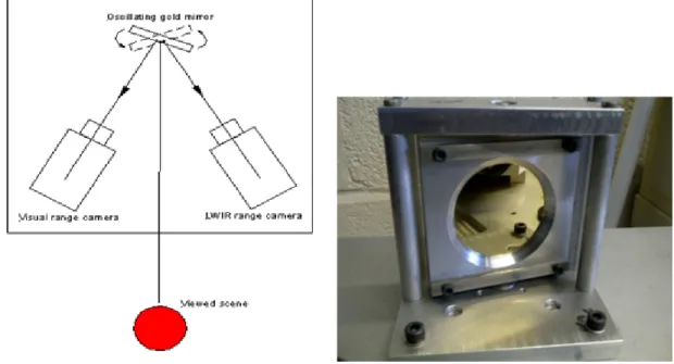
The camera system described here was rst designed in 2010 as a VIS + LWIR multispectral system using an oscillating gold mirror to produce identical optical paths with near-simultaneous image capture between cameras as shown in Figure 1. A gold mirror was used because com-mercially available dichroic mirrors at that time could only separate out the infrared to 1200nm which is not sucient for the thermal range (8-14μm). Gold is commonly used in IR optics
because of its consistently high reectance from the NIR into the LWIR (see Figure 2) and it retains a relatively high reectivity (~80-90%) within part of the VIS range (400-700nm) , making it well suited as a mirror for capturing both VIS and LWIR images. The gold mirror has a protective layer of silicon dioxide which prevents tarnishing of the gold.
Figure 1: LEFT: Schematic of the original oscillating gold mirror camera system, RIGHT: Photograph of the oscillating gold mirror and mount.
3.1 Camera System 3 DESIGN
Figure 2: Reectance spectrum of protected gold from 600nm to 20μm at 45° angle of incidence
(AOI)
Recognition experiments using face images captured via this system and fused in the trans-form domain showed the eectiveness of the camera system and the advantage of the spatial registration of the images. However, the system was limited by the relatively low frequency oscillation of the gold mirror. This problem could not be overcome.
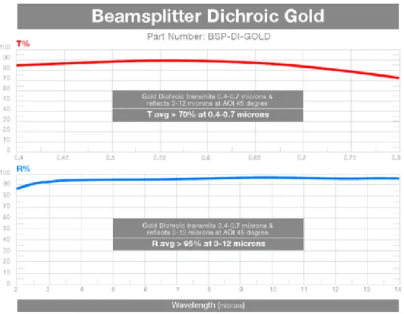
In early 2012, ISP-Optics announced a dichroic beam-splitter with a >70% average trans-mittance across the 400-700nm visible range and an >95% average reectance across the LWIR 8-12μm range as shown in Figure 3. Replacing the gold mirror with this dichroic beam splitter
not only improved the signal level for the VIS camera, but also increased the rate of image acquisition to allow full video rate image capture of the spatially registered images.
3.1 Camera System 3 DESIGN
Figure 3: The VIS range transmittance (T%) and LWIR range reectance (R%) of the ISP Optics dichroic mirror.
Finally, in July 2013, the camera system was expanded to include a Microsoft 'Kinect' depth sensor device as well as an additional dichroic mirror which separated the VIS and NIR portions of the spectrum. The 'Kinect' depth sensor was selected for several reasons: a wide range of driver and software development tools exist for the platform, it is comparatively cheap and the structured light format lends itself well to our system since the projector can be red in parallel with the camera system. Thus a novel multi-spectral + 3D/Depth camera system that is capable of capturing spatially registered VIS, LWIR and Depth video and images has been designed and constructed. The system, as shown in Figure 4, comprises the following sensors:
An EYE R25 thermal sensor using a 12mm (F/0.85) manual focus lens for the LWIR component.(3000-12000nm)
3.1 Camera System 3 DESIGN camera (400-700nm)
A Microsoft KinectTM camera and encoded light laser projector unit which operates in
the NIR region of the spectrum (800-900nm).
The EYE R25 presented the best compromise between image quality and cost. For the VIS cameras an acceptable level of image quality could be achieved for a low cost. The LWIR camera has a limited availability of sensor sizes and germanium lenses. For our relatively close-range application we selected a 12mm lens on the EYE rank 25 to maximise speed and image quality. The VIS camera has a 1/3 crop sensor which when used with a 4.5-10mm zoom lens produces an image with the same focal length and eld of view as the LWIR camera. However, the KinectTM camera has a xed focal length and cannot therefore be adjusted to coincide with
the LWIR and VIS camera images. The one-o registration process carried out to adjust for this is described in Section 3.2.
Due to the limitations of the Kinect hardware, the NIR laser projector cannot be turned o without also turning o the NIR camera, thus separate NIR images and video cannot be captured simultaneously with the other cameras because the NIR laser pattern is projected onto the subject's face. However, it is possible to obtain VIS, LWIR and NIR images and video by physically shuttering the NIR laser projector and illuminating the scene with a 850nm LED array (shown in Figure 5). As the NIR sensor on the Kinect does not have a broad-band response we require this additional illumination in the 850nm wavelength in order to obtain an image, however, this has obvious implications for the fairness of any comparison between lighting modes since all the NIR images are eectively fully illuminated from the front. As such the NIR images are considered separately in our image fusion experiments discussed in Section 5 on page 70. Our system handles the shuttering of the NIR laser projector and NIR LED illumination automatically when capturing an image set, with a slight temporal oset of ~0.5 seconds between the NIR image and the corresponding VIS and LWIR images.
The video streams from the LWIR and VIS cameras are captured using an IDS Falcon Quattro framegrabber running on a Microsoft WindowsTM PC with an Intel i3 530 processor
and 4GB RAM. The software to capture images from the camera streams is written in C++ and uses the OpenCV library while the Microsoft KinectTM is interfaced using the OpenNI library
3.1 Camera System 3 DESIGN and the PrimesenseTM driver. Software for the control of the broadband lighting, LED lighting,
NIR laser shutter and data storage is written in National Instruments LabviewTM and allows
for quick, automatic control of the timed lighting, the NIR shutter and the capture and storage of every image stream. The user is required to enter a subject ID number, select the pose the subject is in and then select one of four lighting modes (front, left, right or low). The software then turns on the appropriate lights and the images are automatically captured, labeled and stored for that subject ID.
Figure 4: A schematic showing the conguration of the multispectral and 3D/Depth camera system components. Two dichroic mirrors are positioned at 45 degrees to the direction of view and reect (R) into the VIS and LWIR cameras the wavebands of light to which they respond whilst transmitting (T) the NIR wavelengths through to the NIR camera. Each dichroic mirror transmits the remaining wavelengths through to the next dichroic mirror or camera.
The cameras are independently xed to a machined aluminum base plate with precision engineered mounts which allow for ne adjustment of the pitch and yaw of the VIS and LWIR cameras. The dichroic mirrors are similarly mounted in precision engineered and xed mounts such that the lters are held vertical and at 45º to their respective cameras. The base plate itself is mounted on a frame to achieve a general head height from the bench top. Fine vertical adjustment of the entire frame and camera system is achieved via an optics-quality lab jack which can raise and lower the assembly. Wide views of the camera system and lighting assembly are shown in Figure 5 and Figure 7.
3.1 Camera System 3 DESIGN
Figure 5: A subject's view of the camera system and setup: 1) The camera system 2) 'Kinect' projector shutter 3) Front lighting mode lamp 4) NIR illumination LED array
3.1 Camera System 3 DESIGN
Figure 6: A plan view of the camera system: 1) LWIR camera 2) VIS camera 3) 'Kinect' NIR depth camera 4) Second dichroic 5) First dichroic 6) 'Kinect' NIR laser projector 7) NIR laser bae
Figure 7: A wide view of the camera system and setup: 1) Left side illumination lamp 2) Camera system 3) Right side illumination lamp 4) Control and acquisition computer
3.2 Camera registration 3 DESIGN
3.2 Camera registration
As discussed in Section 4 the variable focal length of the VIS camera lens allows it to be adjusted such that the VIS and LWIR images coincide. However, the xed focal length of the KinectTM
prevents such an adjustment being made for the depth and NIR images. In order to calculate the ane transformation required to scale and register the VIS/LWIR images with the NIR/Depth images a registration tool was constructed. This consisted of a set of four lights which have an output covering the response of all the camera sensors, mounted within a sheet of TufnolR to
thermally insulate the lights from their mounting. The registration tool was then imaged using the camera system.
The images of the registration tool were then loaded into the MatlabTM control point
selec-tion tool (available in the image processing toolbox). An example of this process is shown in Figure 8. The centers of the light points in the VIS and corresponding NIR image are manually marked and the ane transform required to register the two sets of points is then calculated. This registration process and ane transform calculation is only required once. The transform is then automatically applied to the NIR/Depth images at point of capture and storage.
Figure 8: The registration tool as viewed by the NIR/Depth (1) and VIS (2) cameras. The registration points selected via the MatlabTM registration function can be seen.
3.3 Face Databases 3 DESIGN
3.3 Face Databases
Using the novel, multispectral and depth camera systems described in 3.1 on page 31, a database of face images has been generated.
The database consists of 42 subjects imaged during two separate sessions using the above camera system under varying pose and illumination conditions. The subject and camera system were situated in a blacked out room to remove any ambient light eects during image capture. Illumination is applied via two 12W halogen lights placed behind and to either side of the camera system and directed at the subject. Each light has a computer controlled power supply and the lighting variations and image capture are computer controlled. All images are cropped to 128x128 pixels and manually normalised for eye position and head rotation such that the line of the eyes is parallel to the x-axis of the image plane. Each session was conducted over a month long period with approximately one year between the sessions. There was no control of the ambient room temperature during either capture session.
The images from session one are obtained as follows: 30 subjects
Lighting modes consist of front, side and low lighting. The side lights (shown in Figure 7) are positioned at 30º to the subject's face. The pose and lighting variations are intended to simulate an environment with uncontrolled, non-uniform illumination in which the subject changes position. This is referred to as 'Lighting mode 1' or LM1
Each subject is imaged under front, left side and right side poses, with each lighting mode for each pose
Each subject is imaged wearing eyeglasses and in the front pose, for each lighting mode. Where the subject did not have their own eyeglasses a pair was provided
The capture process under each lighting and pose variation is repeated for each subject All images are cropped to 128x128 pixels and normalised for eye position and head rotation
3.3 Face Databases 3 DESIGN Therefore for session one each subject has 24 images for each spectral modality and depth image modes. There are three spectral modality images (VIS, NIR, LWIR) and a 2.5D/depth image mode at each capture, thus for each subject there are4×24 = 96images and a total of 96×30 = 2880 images for session one. An sample showing the lighting variations for LM1 is
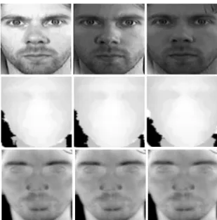
shown in Figure 9.
Figure 9: An example of the LM1 lighting variations for the front pose VIS (rst row) depth (second row) LWIR (third row) images. From left to right: Front-lit, side-lit and low-light.
The images from session two are obtained as follows:
30 subjects, 18 of which were imaged in session one approximately one year previously Lighting modes consist of front, side and low lighting. The side lights (shown in Figure
7) are positioned at 70º to the subject's face and the power of the lamps was increased. The pose and extreme lighting variations are intended to simulate an environment with harsh highly directional, non-uniform, uncontrolled lighting in which the subject changes position. This is referred to as 'Lighting mode 2'
Each subject is imaged under front, left side and right side poses, with each lighting mode for each pose
3.3 Face Databases 3 DESIGN Each subject is imaged wearing eyeglasses and in the front pose, for each lighting mode.
Where the subject did not have their own eyeglasses a pair was provided.
The capture process under each lighting and pose variation is repeated for each subject All images are cropped to 128x128 pixels and normalised for eye position and head rotation
with the line of the eyes parallel to the x-axis of the image plane
Therefore for session two each subject has 24 images for each spectral modality and depth image modes. There are three spectral modality images (VIS, NIR, LWIR) and a 2.5D/depth image mode at each capture, thus for each subject there are4×24 = 96images and a total of 96×30 = 2880 images for session two. An sample showing the lighting variations for LM2 is
shown in Figure 10.
Figure 10: An example of the LM2 lighting variations for the left side pose VIS (rst row) depth (second row) LWIR (third row) images. From left to right: Front-lit, side-lit and low-light
With a total of 42 subjects our databse can be considered small scale in comparison with other databases used in similar research. The size is primarily due to the practicalities of obtaining subjects whilst completing the research in a reasonable timescale, as well as the self-funded nature of the research. As noted in [41] there is no database of registered multispectral VIS, NIR, LWIR and 2.5D/3D face images so making a direct comparison with our database
3.3 Face Databases 3 DESIGN is not possible. The authors of [41] generated their own database of 100 subjects using their camera system although it is worth noting that the research was funded by grants from the National Research Foundation of Korea and the Ministry of Knowledge Economy (Korea) and the database is not available to the public.
There are, however, multispectral face databases available which are commonly used in multispectral face recognition research. For comparison to our own database in terms of subject numbers and image type, these are:
Equinox Face Database [89] contains 300 subjects VIS, SWIR, MWIR and LWIR. It was funded under a US DARPA program but is no longer available to the public.
Near Infrared Visible Light Database (ND-NIVL) [5] contains 574 subjects imaged in VIS and NIR in front pose with normal indoor lighting.
ASU Database [96] contains 96 subjects imaged in VIS and LWIR modalities under varying indoor and outdoor lighting and with eyeglasses where the subject required them. IRIS Database [51] contains images of 30 subjects in VIS and LWIR taken under varying
expression pose and illumination.
IRIS-M3 Database [13] contains images of 80 subjects in VIS and LWIR along with hy-perspectral divisions within the VIS band. The subjects are imaged under indoor and outdoor lighting conditions.
WVUM Database contains images of 50 subjects in VIS and SWIR. The VIS images are take in front prole with the SWIR images under varying pose. The SWIR images are taken in 10nm sub-bands of the SWIR band.
3.4 Eyeglasses Compensation 3 DESIGN
3.4 Eyeglasses Detection and Compensation
A LWIR image of a subject wearing eyeglasses is unsuitable for face recognition. The opacity of the glass to the LWIR light results in large black areas which occlude information that is important for face recognition.
There have been attempts to develop a suitable method of compensation for the presence of eyeglasses in LWIR images prior to fusion with other spectral images. For example, in [44] an average eye is constructed by averaging all of the LWIR eye images in a database. The average eye is then rotated and transformed into position over the eyeglasses within an LWIR image. Alternative methods for eyeglasses compensation have also been proposed in which the LWIR features are modeled to allow the reconstruction of the LWIR image that would have been obtained without eyeglasses [93]. However the process is computationally demanding, which is undesirable for a real-time system. Also, the presented results, based on the correlation between the reconstruction and the average image for a subject, are not extensive or particularly convincing.
A more desirable solution is to use the VIS image information to estimate the occluded LWIR eye image. There has been some work to identify a transform between image modalities, specically the VIS and IR spectral modes. In [17] a patch-based transformation of VIS and NIR image pairs is used to synthesise a VIS face image from a given NIR face image with excellent results. Whilst an explicit global manifold for the transform is not learned, a local linear mapping between VIS and NIR face images is shown to exist. The mapping between VIS and NIR modalities using Local Linear Embedding (LLE) is also shown to preserve the local geometry between two VIS and NIR images. This is in contrast to [22] where LWIR images are converted to VIS images for face recognition using Sophisticated Local Linear Embedding (SLLE) which does not assume that the local geometry is preserved between two VIS and LWIR images. This is discussed further in Section 3.4.2.
A method of synthesising the occluded LWIR eye image from the VIS image using a local linear mapping similar to those described in [17, 22, 62] is employed in this paper. A description of this method is given in Section 3.4.1.
3.4 Eyeglasses Compensation 3 DESIGN 3.4.1 Mapping of VIS to LWIR Eye Images
Using theN VIS and LWIR pairs of normalised front pose images without eyeglasses from the database described in Section 3.3, a set of VIS and LWIR eye image pairs(ϕ1
i,ϕ2i) (i= 1,2...N)
of64×64pixels are extracted, where ϕ1
i is a VIS eye image andϕ2i is the LWIR image of the
same eye. Each eye image is divided into M overlapping patchesP that are16×16 pixels in
size and have an overlapping region of 12×12 pixels. A set of patches for an eye image can
therefore be given asPj,k where(j= 0,1...m−1)is the number of patches sampled in the row
direction and(k= 0,1...n−1)is the number of patches sampled in the column direction giving
a total ofM =m×n= 13×13 = 169patches per eye image.
For each patch in a set P1
j,k extracted from a VIS eye image ϕ1iwe calculate the LBP
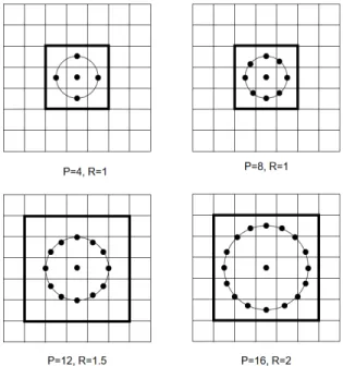
histograms at 7 dierent resolutions using the Multiresolution Local Binary Pattern analysis (MLBP) as described in [17]. The MLBP is an ecient, rotation invariant method of texture analysis using local binary patterns [57]. In MLBP the standard LBP operator which calculates the value of a central pixel by thresholding, weighting and summing pixels within a surrounding neighbourhood is adapted to work at dierent resolutions. The central pixel neighbourhood for MLBP is dened by a variable radius R and sample point number P. The dierent LBP resolutions are obtained by varying the pixel radius R and the number of sample points P to obtain LBP histograms at various resolutions. An example how these point and radius values are congured is shown in Figure 11.
3.4 Eyeglasses Compensation 3 DESIGN
Figure 11: Examples of varying point number and radius value congurations used in MLBP.
The LBP histogram computed at each resolution is normalised and stored in a cell ar-ray such that we can reference for a given patch Pj,k1 from eye image ϕ1i the LBP histogram
{Hj,k(LBPP,R)}where the sample point number and radius values used are(P, R)=(4,1),(8,1),(12,1.5),(8,2),(16,2),(16,3),(24,3).
By repeating this for all eye images extracted from a database we build a cell array which can be used as a dictionaryD1 consisting of an entry for each VIS eye image and the LBP histograms
extracted at each resolution for each patch therein. Each row of D1 indexes the(j, k) patch
positions and each column indexes the VIS eye image extracted from the database. In parallel to this we have the dictionaryD2 consisting of the corresponding LWIR eye imagesϕ2
i and the
LWIR eye image patchesP2
j,k.
For a new eye image pair (ϕ3
i, ϕ4i) where we wish to synthesise the LWIR image ϕ4i, we
rst compute the LBP histograms {Hj,k(LBPP,R)} for each patch Pj,k3 of the VIS eye image
ϕ3i in the same manner as above. For each patch ofϕ3i we compute the similarity at each LBP resolution for each column in the corresponding row of dictionary D1 . The LBP similarity is calculated using the histogram intersection such that for for two histogramsH1 andH2 at the