Header Body Footer Margin Notes i 8 -i 7 ? 6 i 1 -i 3 i 10 -i 9 6 ? i 11 i 2 ? 6 6 ? i 4 6 ? i 5 6 ? i 6
1 one inch + \hoffset 2 one inch + \voffset 3 \oddsidemargin = 0pt 4 \topmargin = -7pt 5 \headheight = 12pt 6 \headsep = 25pt 7 \textheight = 591pt 8 \textwidth = 418pt 9 \marginparsep = 10pt 10 \marginparwidth = 85pt
11 \footskip = 30pt \marginparpush = 7pt (not shown) \hoffset = 0pt \voffset = 0pt
Body Footer Margin Notes i 8 -i 7 ? 6 i 1 -i 3 i 10 -i 9 6 ? i 11 6 i 6
1 one inch + \hoffset 2 one inch + \voffset 3 \evensidemargin = 35pt 4 \topmargin = -7pt 5 \headheight = 12pt 6 \headsep = 25pt 7 \textheight = 591pt 8 \textwidth = 418pt 9 \marginparsep = 10pt 10 \marginparwidth = 85pt
11 \footskip = 30pt \marginparpush = 7pt (not shown) \hoffset = 0pt \voffset = 0pt
Multi-Objective Optimisation Methods Applied
to Aircraft Techno-economic and Environmental
Issues
C. Tsotskas
<
>
Craneld University, School of Engineering, Department of Power and Propulsion Dissertation (Full Time PhD)
Christos Tsotskas
PhD
Academic Year: 2010-2014
Supervisors: Prof. A. M. Savill, Dr T. Kipouros Date of Initial Registration: 7 November 2010
Date of Submission: 7 November 2014
This thesis is submitted in partial fullment of the requirements for the degree of Doctor of Philosophy.
©Craneld University 2014. All rights reserved. No part of this publication may be reproduced without the written permission of the copyright owner.
v
To my parents and other half, for the time spent apart.
Christos Tsotskas November 2014
Stouc goneÐc mou kai sto llo mou misì, gia to qrìno pou touc stèrhsa.
Xrhstoc Tsotskac Noembrioc 2014
vii For the goal is not the last, but
the best. Aristoteles (Second Book of Physics, ii, 194a 32-33)
To rìlo tou tèlouc den ton diek-dikeÐ kje èsqato shmeÐo, all mìno to bèltiston. Aristotèlhc (Fusik, II, ii, 194a 32-33)
Be content with the present, but seek after what is best. Isocrates, To Demonicus, section 29
Stèrge mèn t parìnta, z tei dè t beltÐw. Isokrthc, Proc Dhmìnikon, enìthta 29
ix
Declaration
This dissertation is the result of my own work and includes nothing which is the outcome of work done in collaboration. This dissertation contains a total of 92330 words and 83 Figures in 291 pages.
xi
Acknowledgements
The research has been carried out at Craneld University between November 2010 and November 2014.
The research project has received funding from the European Union's Sev-enth Framework Program (FP7/2007-2013) for the Clean Sky Joint Technology Initiative under grant agreement N0 CJSU-GAMSGO-2008-001.
I would like to thank my supervisors Prof. A. M. Savill and Dr T. Kipouros for their patience and guidance throughout my rst research steps.
I would also like to thank CLEANSKY System for Green operations team, Dr V. Sethi and his team for providing access to GATAC framework and technical guidance when integrating and using GATAC.
I express my gratitude to CLEANSKY committee at Craneld University and Bodossaki Foundation, Greece for providing additional support to carry out my research.
I would like to thank the German Academic Exchange Service (DAAD) for giving me the opportunity to meet with Prof. S. Turek and Dr M. Razzaq from TU-Dortumnd, Germany, where we exchanged signicant scientic expertise and knowledge.
I would like to thank Dr G. T. Parks and Dr V. Sethi for their feedback. Last but not least I would like to thank my family and my wife who stayed by my side throughout this journey. Their support has been invaluable.
xiii
Abstract
Engineering methods that couple multi-objective optimisation (MOO) techniques with high delity computational tools are expected to minimise the environmental impact of aviation while increasing the growth, with the potential to reveal in-novative solutions. In order to mitigate the compromise between computational eciency and delity, these methods can be accelerated by harnessing the compu-tational eciency of Graphic Processor Units (GPUs).
The aim of the research is to develop a family of engineering methods to support research in aviation with respect to the environmental and economic aspects. In or-der to reveal the non-dominated trade-o, also known as Pareto Front(PF), among conicting objectives, a MOO algorithm, called Multi-Objective Tabu Search 2 (MOTS2), is developed, benchmarked relative to state-of-the-art methods and ac-celerated by using GPUs. A prototype uid solver based on GPU is also developed, so as to simulate the mixing capability of a microreactor that could potentially be used in fuel-saving technologies in aviation. By using the aforementioned methods, optimal aircraft trajectories in terms of ight time, fuel consumption and emis-sions are generated, and alternative designs of a microreactor are suggested, so as to assess the trade-os between pressure losses and the micro-mixing capability.
As a key contribution to knowledge, with reference to competitive optimisers and previous cases, the capabilities of the proposed methodology are illustrated in prototype applications of aircraft trajectory optimisation (ATO) and micro-mixing optimisation with 2 and 3 objectives, under operational and geometrical constraints, respectively. In the short-term, ATO ought to be applied to existing aircraft. In the long-term, improving the micro-mixing capability of a microre-actor is expected to enable the use of hydrogen-based fuel. This methodology is also benchmarked and assessed relative to state-of-the-art techniques in ATO and micro-mixing optimisation with known and unknown trade-os, whereas the former could only optimise 2 objectives and the latter could not exploit the com-putational eciency of GPUs. The impact of deploying on GPUs a micro-mixing ow solver, which accelerates the generation of trade-o against a reference study, and MOTS2, which illustrates the scalability potential, is assessed.
With regard to standard analytical function test cases and verication cases in MOO, MOTS2 can handle the multi-modality of the trade-o of ZDT4, which is a MOO benchmark function with many local optima that presents a challenge for a state-of-the-art genetic algorithm for ATO, called NSGAMO, based on case studies in the public domain. However, MOTS2 demonstrated worse performance on ZDT3, which is a MOO benchmark function with a discontinuous trade-o, for which NSGAMO successfully captured the target PF. Comparing their overall performance, if the shape of the PF is known, MOTS2 should be preferred in problems with multi-modal trade-os, whereas NSGAMO should be employed in
discontinuous PFs. The shape of the trade-o between the objectives in airfoil shape optimisation, ATO and micro-mixing optimisation was continuous. The weakness of MOTS2 to suciently capture the discontinuous PF of ZDT3 was not critical in the studied examples.
First, the climb phase of a medium-haul aircraft was optimised by employ-ing MOTS2 and NSGAMO, where both optimisers revealed comparable results, and the genetic algorithm was assessed more appropriate because of the span of solutions and the value of hypervolume quality indicator. When optimising the climb phase, the MOTS2' trade-o was narrower than NSGAMO. In terms of fuel-eciency in the PF, NSGAMO's extreme trajectory outperforms MOTS2 by approximately 80 kg (6.38% fuel saving). Similarly, the fastest trajectory dis-covered by NSGAMO is 35 seconds shorter (4.07% time eciency) against the most fuel ecient trajectory. Also, the ight path trends revealed by NSGAMO are closer to the theoretical optimal cruise-climb trajectories.
Second, by using MOTS2, a 3-phase trajectory was optimised to simultan-eously minimise the fuel burn, ight time and NOx emissions. When comparing the extreme designs from the discovered PF, the optimal solutions reveal an im-provement of up to 1.13 minutes (2.4% shorter travel time), 171.44 kg of consumed fuel (8.87% fuel savings) and 2.15 kg of NOx (4.37% emissions savings). In both ATO applications, specifying the altitude of the rst segment of the ight is the most signicant factor with respect to the optimum behaviour.
Third, the internal design of a micro-reactor was optimised by altering the geometrical layout of the device and the ow characteristics. When compared to a reference study, the simulation time in the design process was improved by ap-proximately 20 times and the quality of the generated trade-o increased by 5% in terms of hypervolume. The generated trade-o suggested designs that maximised the micro-mixing capability up to a factor of 227% in terms of normalised vorticity magnitude, whereas the normalised dierence in total pressure was as low as 1.8%. A selected compromise design achieved more than 30% improvement in both ob-jectives. The performance of the discovered designs in micro-mixing optimisation is very similar with respect to the area of low dierence of total pressure, even after the considerable speed up. However, the vorticity magnitude (i.e., the mix-ing capability) improved by approximately 20%. The suggested compromise design geometrically is very similar to the minimum pressure losses design, but relatively distant in terms of performance (mainly because of the ow speed), which is con-sistent with experimental observations, where minor changes can bring dramatic changes in performance.
Future directions suggest linking the optimisation methodology to decision sup-port systems and integrate multiple principles, and improve the levels of automa-tion and scope of the research in transport and other elds.
Contents
Abstract xiii
Table of Contents xv
List of Figures xix
List of Tables xxiii
Listings xxv
Acronyms and Nomenclature xxvii
1 Introduction 1
1.1 Background . . . 1
1.1.1 Improving Operations by Optimising Aircraft Trajectories . 2 1.1.2 Evolving Aircraft Technology by Optimising Micro-Mixing . 2 1.1.3 The Role of Simulation and Optimisation . . . 5
1.2 Aims and Objectives . . . 6
1.3 Overall Project Methodology. . . 7
1.4 Outline of Thesis . . . 10
1.5 Contribution to Knowledge. . . 11
2 Literature Review 13 2.1 Initial Contributions . . . 13
2.2 Computational Methods for Aircraft Technology for Mixing by us-ing CFD . . . 14
2.3 Accelerating Computational Methods of Computational Fluid Dy-namics . . . 15
2.4 Optimisation Applications by using CFD . . . 17
2.5 Accelerating Optimisation Methods . . . 18
2.6 Optimising Aircraft Trajectories . . . 19
2.7 Optimisation and Multi-Objective Optimisation . . . 27
2.8 Summary and Linking with next Chapter . . . 30 xv
3 Technical Description of Computational and Optimisation Tools 33
3.1 Multi-Objective Optimisation Algorithm . . . 33
3.1.1 Introduction . . . 33
3.1.2 Trends in Multi-Objective Tabu Search . . . 36
3.1.3 The Design and Implementation of MOTS2 . . . 37
3.1.3.1 Describing the Dierent Types of Memories . . . . 40
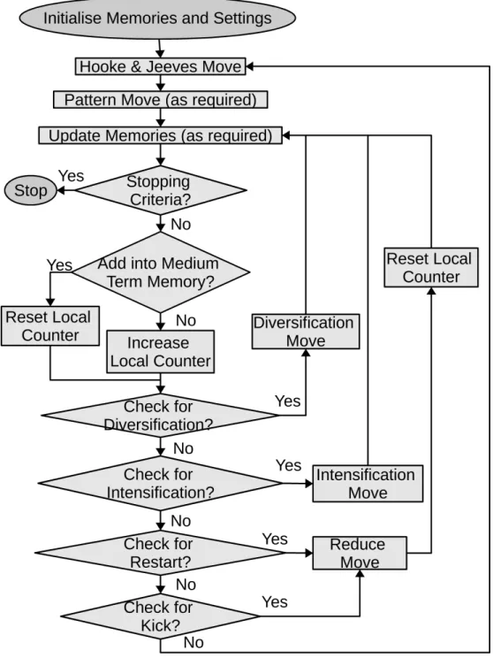
3.1.3.2 Algorithmic Structure . . . 44
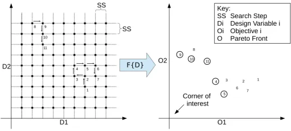
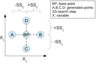
3.1.3.3 Frequently Performed Moves . . . 48
3.1.3.4 Conditionally Performed Moves . . . 52
3.1.4 Constraints and Objectives Handling . . . 54
3.1.5 Unique Features . . . 55
3.1.6 Verifying MOTS2 . . . 58
3.1.6.1 Benchmarking the Family of ZDT Functions for Bi-objective Optimisation . . . 59
3.1.7 Validating MOTS2 . . . 65
3.1.7.1 Airfoil Shape Optimisation . . . 66
3.2 Parallel Multi-Objective Optimisation Algorithm . . . 70
3.2.1 Trends in Parallel Implementations . . . 71
3.2.2 Parallelisation Strategy for External Evaluation . . . 72
3.2.3 Scalable Multi-Objective Optimisation Problems . . . 74
3.2.4 Massive Parallelisation Strategy . . . 74
3.2.4.1 Software and Hardware Perspectives . . . 75
3.2.4.2 Design Decisions and Concerns . . . 76
3.2.4.3 Implementation . . . 78
3.2.5 Assessing GPU-MOTS2 on a Simple Benchmark . . . 79
3.2.6 Investigating the Interactions between the GPU Hardware and Algorithm Conguration on GPU-MOTS2 . . . 84
3.2.7 Discussion and Future Work . . . 87
3.3 Flow Solver Simulation . . . 89
3.3.1 Background . . . 89
3.3.2 Graphics Accelerators Programming Model . . . 90
3.3.3 Lattice Boltzmann Method for D3Q19 . . . 92
3.3.4 Porting LBM to GPU . . . 94
3.3.4.1 Algorithm . . . 97
3.3.4.2 Memory Access . . . 99
3.3.4.3 Execution . . . 100
3.3.5 Interfacing and Conguration Settings . . . 101
3.3.6 Architecture of the Flow Solver . . . 102
3.3.7 Simulating the Fluid Flow in the Microreactor by using GPU-LBM . . . 105
CONTENTS xvii
3.4 Summary and Linking with next Chapter . . . 113
4 Applications 117 4.1 Aircraft Trajectory Optimisation . . . 117
4.1.1 Trajectory Optimisation of Climb Phase . . . 117
4.1.1.1 Problem Description . . . 117
4.1.1.2 Methodology for the Climb Phase . . . 118
4.1.1.3 Preparing the Multi-Objective Aircraft Trajectory Optimisation Process for Climb . . . 122
4.1.1.4 Optimisation Algorithms. . . 124
4.1.1.5 Optimising Climb - Results and Discussion. . . 126
4.1.1.6 Identied Issues. . . 133
4.1.2 Trajectory Optimisation of Climb, Cruise and Descent . . . 134
4.1.2.1 Problem Description . . . 134
4.1.2.2 Methodology for the 3-Phase Trajectory . . . 135
4.1.2.3 Preparing the Multi-Objective Optimisation Pro-cess of the 3-phase ATO . . . 140
4.1.2.4 Optimisation Progress . . . 151
4.1.2.5 Comparing the Variables and Objectives . . . 154
4.1.2.6 Analysing Aircraft Trajectories . . . 155
4.1.2.7 Identied Issues. . . 161
4.2 Micro-Mixing Optimisation of Microreactor. . . 163
4.2.1 Problem Description . . . 163
4.2.2 Methodology . . . 164
4.2.3 Preparing the Multi-Objective Optimisation Process of the Reaction Mixing . . . 169
4.2.4 Optimising Environmentally-friendly devices - Results and Discussion . . . 173
4.2.5 Identied Issues . . . 196
5 Concluding Remarks and Discussion 199 5.1 Main Research Contributions . . . 199
5.2 Discussion of Findings . . . 200
5.3 Main Conclusions . . . 204
5.4 Assumptions and Limitations . . . 206
5.5 Future Work . . . 210
5.5.1 Improving the Methods. . . 210
5.5.1.1 Improving Optimisation Process and Procedures . 211 5.5.1.2 Improving Process and Procedures for Aircraft Tra-jectory Optimisation . . . 213
5.5.1.3 Improving Process and Procedures for Multi-Disciplinary
Design Optimisation of the Microreactor . . . 215
5.5.2 Expanding the Applications . . . 215
5.5.2.1 Future Aircraft Trajectory Studies . . . 216
5.5.2.2 Future Multi-Disciplinary Design Optimisation Stud-ies . . . 218
5.5.3 Improving the Tools . . . 220
5.5.3.1 Improving the Optimiser . . . 220
5.5.3.2 Improving the Flow Solver . . . 224
5.5.4 Long-Term Extensions . . . 225
References 227 Appendices 257 A Scalability of GPU-MOTS2 258 Corrections 258 A Rebuttal - TEMPORARY Chapter 263 A.1 Statement of Thesis Deciencies . . . 263
A.2 Common Corrections . . . 266
A.3 Corrections suggested by Dr Parks . . . 267
A.3.1 Generic Corrections . . . 267
A.3.2 Specic Corrections . . . 269
A.3.3 Annotated Corrections . . . 274
A.3.4 Other rebuttal comments . . . 275
A.4 Corrections suggested by Dr Sethi . . . 275
A.4.1 Corrections in Abstract . . . 275
A.4.2 Corrections in Introduction . . . 276
A.4.3 Corrections in Literature . . . 278
A.4.4 Corrections in Computational Tools . . . 279
A.4.5 Corrections in Applications . . . 281
A.4.6 Corrections in Conclusions . . . 284
List of Figures
1.1 Abstract Optimisation Methodology . . . 8
2.1 GATAC Top Level Design [167] . . . 25
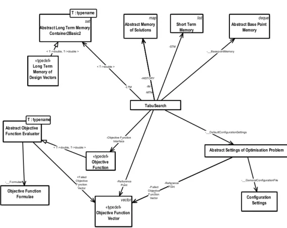
3.1 MOTS2 Architecture . . . 38
3.2 Tabu Search Memories . . . 41
3.3 MOTS2 Algorithm Flow Diagram . . . 45
3.4 An Instance of MOTS2 on a 2 Decision Variables and 2 Objective Optimisation . . . 47
3.5 Hooke and Jeeves Move in Decision Space . . . 49
3.6 Methodology for Verifying MOTS2 against Test Functions . . . 59
3.7 ZDT1 EAF . . . 62
3.8 ZDT2 EAF . . . 62
3.9 ZDT3 EAF . . . 62
3.10 ZDT4 EAF . . . 62
3.11 ZDT6 EAF . . . 62
3.12 Normalised Hypervolume Boxplots for ZDT Test Functions . . . 62
3.13 Demonstrating the Performance of NSGAMO (in the Plots Referred to as NSGAMO3) on ZDT1 Against State-of-the-art Optimisation Algorithms [220] . . . 63
3.14 Demonstrating the Performance of NSGAMO (in the Plots Referred to as NSGAMO3) on ZDT3 Against State-of-the-art Optimisation Algorithms [220] . . . 64
3.15 Demonstrating the Performance of NSGAMO (in the Plots Referred to as NSGAMO3) on ZDT6 Against State-of-the-art Optimisation Algorithms [220] . . . 65
3.16 Methodology for Validating MOTS2 against Low Fidelity Physics . 66 3.17 XFOIL EAF . . . 70
3.18 Normalised HV Boxplots for XFOIL. . . 70
3.19 Parallel Evaluation Scheme on GPU . . . 78
3.20 Methodology for Verifying the Scalability of GPU-MOTS2 against a Single Test. . . 81
3.21 Scalability of GPU-MOTS2 when the Number of Variables Increases 83 xix
3.22 3 Dimensional 19 Microscopic Densities - D3Q19 Model . . . 92
3.23 GPU-LBM Class Diagram . . . 104
3.24 GPU-LBM Sequence Diagram . . . 105
3.25 a) Perspective View of the Microreactor Model, b) Prole View of the Microreactor Model in Physical Units (not to scale) [45] and c) Prole View of the Microreactor Model in Lattice Units (not to scale) [46] . . . 108
3.26 View of the Bae Plate in Lattice Units [64] . . . 109
3.27 The Flow Pattern between Experimental Measurements and Simu-lation are Qualitatively Compared . . . 110
3.28 Vector Field . . . 111
3.29 Vector Field with Scaled Vectors. . . 111
3.30 Velocity Prole of the Microreactor, perpendicular to the Flow . . . 112
3.31 Velocity Prole along the Microreactor . . . 113
4.1 Methodology to Compare MOTS2 against NSGAMO for ATO in the Climb Phase . . . 120
4.2 Trajectory Modelling . . . 121
4.3 Outline of Optimisation Process on an Instance of a 3-Segment Flight122
4.4 Comparing the Trade-Os and the Compromise Designs . . . 126
4.5 Generated Trajectories . . . 128
4.6 Design Variables to Objective Functions Relationships. . . 131
4.7 Mapping of Decision Space to Objective Space of the PF in Parallel Coordinates Projection . . . 132
4.8 Methodology for Optimising a 3-Phase Trajectory by using MOTS2 140
4.9 Engine Model Schematic . . . 141
4.10 HERMES Aircraft Performance Model Flow Chart [263] . . . 145
4.11 Calculating the Corrected Emission Index of NOx at Altitude by using the Emission Model [272] . . . 147
4.12 MOTS2 Search Progress in 3-phase ATO . . . 152
4.13 Parallel Coordinates Projection of the Objective Space of 3-phase ATO . . . 153
4.14 Comparing the Variability from HISTORY and PF with Reference to Tables 4.5 and 4.8 . . . 156
4.15 Relative Objectives' Improvement . . . 157
4.16 Comparing the Trajectory Altitude Proles . . . 159
4.17 Comparing the Trajectory Speed Proles . . . 159
4.18 Zooming trajectory altitude proles . . . 160
4.19 Methodology for Comparing MOTS2 and GPU-LBM against the Original Multi-Objective Tabu Search and the Original LBM . . . . 165
LIST OF FIGURES xxi
4.21 Coverage of Decision Space (from HISTORY) . . . 174
4.22 Optimum Decision Space and Objective Space (from MTM) . . . . 175
4.23 Histogram of rst Decision Variables of the Optimal and Complete Dataset . . . 177
4.24 Histogram of Second Decision Variables of the Optimal and Com-plete Dataset . . . 177
4.25 Histogram of Third Decision Variables of the Optimal and Complete Dataset . . . 177
4.26 Comparing the Pareto-Front (PF) between the Current Implement-ation and the Original one from [64] . . . 179
4.27 Optimisation Search Pattern at 1877 Total Evaluations . . . 182
4.28 Optimisation Search Pattern at 3805 Total Evaluations . . . 182
4.29 Optimisation Search Pattern at 7711 Total Evaluations . . . 183
4.30 Optimisation Search Pattern at 9676 Total Evaluations . . . 183
4.31 Optimisation Search Pattern at 11743 Total Evaluations . . . 184
4.32 Complete Optimisation Search Pattern, PF and Selected Designs (listed in Table 4.13) . . . 184
4.33 PF Progress (Related to Figs. 4.27 to 4.32) . . . 185
4.34 The Progress of the PF at the Beginning of the Search, as an Interim Snapshot of the Trade-O from Fig. 4.33 . . . 186
4.35 Monitoring the Number of Invocations of the Provided Moves Through-out the Optimisation Search . . . 188
4.36 The Activity of the Optimiser Through the Number of Consecutive Unsuccessful Iterations . . . 188
4.37 Zooming into the Number of Invocations of the Provided Moves Throughout the Optimisation Search . . . 190
4.38 Bae Plate for the Datum Design . . . 192
4.39 Bae Plate for the Design with Maximum Vorticity Magnitude . . 192
4.40 Bae Plate for the Compromise Design . . . 192
4.41 Bae Plate for the Design with Minimum Dierence in Total Pressure192
4.42 Trade-o of Selected Designs while Varying Flow Speed (the Flow Speed Increases when Moving from Left to Right) . . . 193
4.43 Velocity Contours in the mid Plane of the Datum Design . . . 194
4.44 Velocity Contours in the mid Plane of the Design with Maximum Vorticity Magnitude . . . 194
4.45 Velocity Contours in the mid Plane of the Compromise Design . . . 195
4.46 Velocity Contours in the mid Plane of the Design with Minimum Normalised Dierence in Total Pressure. . . 195
A.1 Scalability of the Elapsed Time of GPU-MOTS2 on ZDT1 when the Number of Variables Increases . . . 258
A.2 Scalability of the Elapsed Time of GPU-MOTS2 on ZDT2 when the Number of Variables Increases . . . 259
A.3 Scalability of the Hypervolume Indicator of GPU-MOTS2 on ZDT1 when the Number of Variables Increases . . . 260
A.4 Scalability of the Hypervolume Indicator of GPU-MOTS2 on ZDT2 when the Number of Variables Increases . . . 261
List of Tables
3.1 Optimisation Conguration Settings for ZDT Benchmark Functions 60
3.2 Features of ZDT Functions . . . 60
3.3 MOTS2 Conguration Settings for Airfoil Shape Optimisation . . . 69
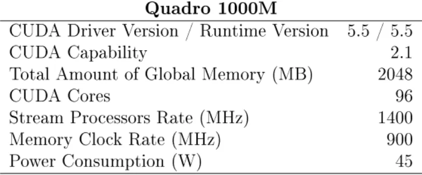
3.4 GPU Hardware Specications to Benchmark the Performance of MOTS2 . . . 77
3.5 GPU-MOTS2 Conguration Settings for Test Functions . . . 82
3.6 GPU-MOTS2 Conguration Settings for Test Functions to Study the Interactions of GPU Hardware and Algorithm Conguration . . 85
3.7 GPU Hardware Specications to Simulate the Microreactor . . . 106
4.1 Climb Flight Envelope for 4-Segments Aircraft Trajectory Optim-isation (ATO) . . . 124
4.2 Optimisation Conguration Settings for Aircraft Trajectory . . . 125
4.3 Principal Component Analysis of the Decision Variables that Belong to the Optimal Trade-O . . . 129
4.4 Hypervolume Indicator . . . 130
4.5 Flight Envelope for 3-phase Aircraft Trajectory Optimisation (ATO) and Mapping to Optimisation Problem Variables . . . 137
4.6 Engine Design Specication . . . 142
4.7 Aircraft Model Specications. . . 144
4.8 Specication of Variables for 3-phase Aircraft Trajectory Optimisa-tion (ATO) with Reference to Table 4.5 . . . 149
4.9 Multi-Objective Tabu Search 2 (MOTS2) Conguration Settings for 3-phase Aircraft Trajectory Optimisation (ATO) . . . 151
4.10 MOTS2 Conguration Settings for Microreactor Optimisation . . . 173
4.11 MOTS2 Conguration Settings to Optimise the Microreactor . . . . 173
4.12 Hypervolume Indicator for Microreactor Mixing . . . 179
4.13 Design and Performance Metrics for Selected Designs from Fig. 4.32 192
Listings
3.1 MOTS2 Top Level Pseudocode . . . 38
3.2 STM Container Class Pseudocode . . . 40
3.3 Container Class Pseudocode . . . 41
3.4 LTM Container Class Pseudocode . . . 43
3.5 Hooke and Jeeves Move Pseudocode . . . 49
3.6 Pattern Move Pseudocode . . . 51
3.7 Intensify Move Pseudocode . . . 53
3.8 Diversify Move Pseudocode . . . 53
3.9 Reduce Move Pseudocode . . . 54
3.10 Pseudocode of the Method to Activate Kick . . . 56
Acronyms and Nomenclature
ALT altitude . . . .120
APM Aircraft Performance Model. . . .118
ATC Air Trac Control . . . .19
ATM Air Trac Management . . . .2
ATO Aircraft Trajectory Optimisation . . . .2
BP Base Point. . . .40
CAS Calibrated Airspeed. . . .123
CFD Computational Fluid Dynamics . . . .3
CPU Central Processor Unit . . . 18
CUDA Compute Unied Device Architecture . . . .15
D3Q19 3 dimensional 19 microscopic densities . . . .89
DACE Design and Analysis of Computer Experiments. . . .212
EAF Empirical Attainment Function . . . .59
EPM Engine Performance Model . . . .118
FMS Flight Management System . . . .21
FPA Flight Path Angle. . . .120
GATAC Green Aircraft Trajectory under ATM Constraints . . . .24
GPU Graphic Processor Unit . . . .7
HISTORY History Memory. . . .40
HPC High Performance Computing. . . .15
ICAO International Civil Aviation Organisation . . . .146
IM Intensication Memory. . . .40
LBM Lattice Boltzmann Method . . . .7
LTM Long Term Memory . . . .40
MOO Multi-Objective Optimisation . . . .6
MOTS2 Multi-Objective Tabu Search 2 . . . .7
MTM Medium Term Memory (full Pareto Front) . . . .40
xxix LIST OF ACRONYMS AND NOMENCLATURE NS Navier-Stokes . . . .14
NSGAMO Nondominated Searching Genetic Algorithm Multi-Objective . . . .22
NSGA-II Nondominated Sorting Genetic Algorithm II . . . .22
PCA Principal Component Analysis . . . .128
PF Pareto-Front . . . .28
RBF Radial Basis Functions. . . .212
SBX Simulated Binary Crossover . . . .22
SIMD Single-Instruction Multiple-Data. . . .91
SIMT Single-Instruction Multiple-Threads. . . .75
SM Symmetric Multiprocessor . . . .72
SPD speed . . . .120
SS Search Step . . . 48
SSRF Search Step Retain Factor . . . .68
SRS Software Requirements Specications . . . .34
STM Short Term Memory (Tabu) . . . .40
avgD average density
blockId.x block index in CUDA
blockDim.x dimension of blocks in CUDA
CO2 Carbon Dioxide . . . .5
did domain index
CD drag coecient . . . .67
CL lift coecient. . . .67
ei lattice velocity
gid global thread index
fi distribution of particles for density i
fieq distribution of particles in equilibrium for density i
i microscopic density index
Kn Knudsen number . . . .17
LX size of computational domain on X-axis
LY size of computational domain on Y-axis
xxxi LIST OF ACRONYMS AND NOMENCLATURE
LZ size of computational domain on Z-axis
lu lattice unit . . . .101
NOx Nitrous Oxides . . . .4
r hole radius in the bae . . . .107
P0 total pressure . . . .171
Re Reynolds number. . . .106
s spacing in the bae . . . .107
t temporal index
threadId.x thread index in CUDA
u macroscopic velocity
wi weights for densityi
x spatial index on the X-axis. . . .112
y spatial index on the Y-axis . . . .112
z spatial index on the Z-axis
∆P0 dierence of total pressure . . . .171
∆t time step
ρ macroscopic density
τ relaxation time
ω vorticity . . . .171
SoTD Statement of Thesis Deciencies . . . .263
P2 Revised Assessment By Dr Parks . . . .263
S2 Revised Assessment By Dr Sethi. . . .263
Chapter 1
Introduction
1.1 Background
The high demand to transfer more passengers and goods along with expanding global economies have been driving the transport trends [1]. Among others, air transport, as a sector, has been growing very fast over the last 40 years [2]. Despite numerous incidents (e.g., market crash), the volume of passengers and goods to be transferred by air has increased tenfold and fourteenfold, respectively, which has a direct impact on the environment and energy use [3]. Economically, in terms of re-turn on investment, airlines have the lowest rate among many other industries [4]. Environmentally, a four-pillar strategy was set to achieve the emission reduction goals, where the rst and second items of the list are related to aircraft technology (i.e., airframe, engines and sustainable biofuels) and ight operations [5]. The faster any solutions become available, the greater the benet for all the stakehold-ers and the quicker the recovery for the planet will be [6]. Hence, dedicated eorts to save fuel and costs are required in every phase of an aircraft's life cycle and operations. The main challenges for air transport [7], which highly conict with each other, are aviation growth, climate change, air quality, aircraft noise, and sustainable development. These problems could be addressed by using technical methods and computational tools [8,9].
There are various procedures so as to accommodate the aforementioned chal-lenging goals [10]: a) decrease the overall number of operations, b) change aircraft type/technology, c) alter aircraft trajectories. As discussed in [1115] and by con-sidering the statistics in [12], the rst option is unlikely to happen, as trac tends to continuously increase [1618]. Therefore, a combination of the last two options seems a viable approach with respect to the initial problem.
The tools and methods developed in this research are expected to assist avi-ation (and similarly related industries) at the operavi-ational and research level. A
multitude of stakeholders could nd interest in the products of this research. Air-lines could use their existing resources in an optimal way while accomplishing both internal and/or external objectives and/or other criteria. Manufacturing industry and academia will possess an alternative way to perform further research studies and analyses, which will increase their potential and knowledge span at the re-search level. Individuals and rere-searchers could carry out their own projects, which will enable them to be more productive and will give them additional capability and exibility to eectively tackle their problems. Ultimately, in the long term, following years of technological improvement, research bodies that focus on the le-gislation and protection of the environment (e.g., Air Trac Management (ATM)) could experiment new strategies and design for a better society.
1.1.1 Improving Operations by Optimising Aircraft
Traject-ories
Aircraft Trajectory Optimisation (ATO) could be readily performed as a more promising short-term solution and is expected to reshape the next generation of
ATM [19]. As a concept, ATO includes all the means and processes, so as to im-prove the ight path of an aircraft. ATOis strongly related toATMbecause it can enhance the mechanisms to coordinate a range of actions from issues related to the ight of a single aircraft to issues concerning international airspace [6]. Operational improvements include a variety of methods of ying, maintaining and loading the aircraft as well as ATM procedures and systems. Frequently, these solutions at-tempt to maximise fuel eciency by minimising ight distance, optimising cruise altitude and speed [20]. This is a straightforward technique that could consider-ably reduce the eect of aircraft operations on the environment with most minimal change(s) to the stakeholders of the aviation industry (aircraft, airport, human resources, other equipment, etc.). By applying optimisation methods, a range of solutions for real-world problems ofATOcan be obtained [21]. Performance-based navigation, a wider concept that uses area navigation as discussed in [22,23], is expected to be an on-going issue until 2020 [24], towards optimising the airspace in order to meet high demand requirements and future needs, even in pilot trials [25].
1.1.2 Evolving Aircraft Technology by Optimising
Micro-Mixing
Changing the type of the aircraft is a massive task that requires huge amounts of time, resources and encompasses potential risk; so it seems to be an alternative long-term solution, because of the high economic and temporal cost [20]. Although the current technology is considerably advanced, relative to the beginning of
avi-1.1. BACKGROUND 3 ation, it has not reached the level of maturity that would allow any scaling in terms of the number of operations. Technological improvements involve changes in the engine and airframe in terms of design and performance [26], the development and use of alternative fuels [27]. As a single cost item, the fuel is responsible for 30% to 40% of total costs [24], where technologies that aim to reduce fuel consumption should also be cost-ecient either in terms of initial investment or maintenance costs. In terms of using alternative fuels, where liquid hydrogen has the largest span for new types of aircraft before 2020, 10% of the fuel used by aircraft is ex-pected to be an alternative fuel by 2017 [24,28]; there is a great uncertainty behind this technology, which ought to be de-risked by carrying out further research. A signicant drive in the evolution of aviation is the advance of Computational Fluid Dynamics (CFD) as discussed in [29].
Investigating alternative energy technology for aircraft has been an on-going topic since the beginning of aviation. Several advanced technological alternatives are predicted to improve the environmental performance of commercial aviation between the years 2030 and 2040 [30,31]. As expected, fairly soon after the com-mercial launch of aircraft for civil ight, several studies have discussed alternative ways of addressing environmental and other concerns, mainly with respect to tech-nology [32]. Similarly, environmental concerns and political pressure concerning the future of aviation have been expressed in [33]. Since then, investigating al-ternative types of fuel, better combustor design, better materials, better tools and methods, and reduction of noise and emissions have been important topics.
Using hydrogen is a viable solution in the long run in order to address envir-onmental concerns along with energy dependency [34,35]. One of the suggestions in [15] was to use hydrogen-powered aircraft, where hydrogen will be used as a fuel by the combustor of the aircraft engine. In general, combining hydrogen with diesel or using lean mixtures of hydrogen in experimental testings have reduced the emissions, but in extreme cases emissions slightly increased [36,37]. Compared to kerosene, hydrogen weighs less [38]. However, a larger volume is required to store enough fuel for operational purposes, and it is very expensive to produce and the eciency is reduced [39,40]. More importantly, hydrogen aircraft congurations have a minimal environmental footprint [34,35,3941]. This concept is further explained in [34], where new designs are presented with very promising results for the future of aviation.
However, in order to use hydrogen on conventional engines, modications are required to achieve a better performance with respect to the environmental im-pact [34]. For instance, implementing cryogenic storage on hydrogen tanks will reduce the size of tanks and could enable existing aircraft to use hydrogen. In gen-eral, this technology has improved over the years and seems a viable solution for achieving environmentally-friendly combustion [34,42]. Nevertheless, using
hydro-gen eectively depends on the geometry of the combustor as shown in [34,39,40]. The shape of the combustor can aect the mixing of fuel and air [39,41]. High tur-bulence makes sure that the fuel is well mixed with air giving a high ame speed, which is of major importance when minimising emissions [43]. Hence, environ-mentally-friendlier combustion depends on micro-mixing, which obviously requires small-scale devices [44].
Fundamentally, in order to enable hydrogen-powered aircraft, small devices that perform mixing at small scale are required, such as microreactors. A mi-croreactor, also known as a miniaturised reactor, is a small-scale device that can mix reacting agents by molecular diusion with applications in energy generation, medical diagnostics, drug discovery, etc. It is a promising solution, whose mix-ing capability has been investigated experimentally, where it is clearly stated that the geometry of the reactor needs to be optimised to improve the mixing capabil-ity [45] and a number of concepts have been explored via simulation [46]. Bringing together computational and experimental methods will be very benecial for the development process of environmentally-friendly devices [47]. However, specialised tools and methods are needed to design such devices and to study their perform-ance, because of the complexity of natural phenomena that take place at such a small scale [46,48,49]. When designing the shape of the microreactor, two import-ant factors to consider are the mixing capability and the pressure losses, which both ought to be optimised at the same time.
In order to reduce gaseous emissions, moving away from stoichiometric com-bustion (i.e., the ideal comcom-bustion that combines the correct amount of air and fuel), which is related to high ame temperature, could be an alternative ap-proach [50,51]. The challenge in combustor design is to reduce the high ame temperature oxidation of nitrogen [50], which is mainly responsible for Nitrous Oxides (NOx) emissions. By providing a more homogeneous fuel/air mixture while
operating at a lean fuel/air ratio,NOx emissions decrease dramatically because of
the low temperature of the ame and the complete removal of hot spots in the combustion area [52]. So, lean or rich combustion is required to reduce the high ame temperature. The air has to be redistributed to minimise the liner cool-ing ow and up to 70% of the combustor air ow has to be premixed with the fuel. By using premixing, an increasingly homogeneous mixture is formed that prevents high-temperature concentration. Consequently, better mixing requires a combustor design with a high swirl. In addition, in premixing, auto-ignition and ashback might occur when the combustor pressure is high. Dierent types of combustors have been invented, among which lean premixed prevaporised has the potential to reduceNOx, up to 70% on take-o, compared to a standard reference.
In lean premixed prevaporised combustor, ows are separated for fuel atomisation and fuel mixing and evaporation, which achieves high mixture uniformity, but at
1.1. BACKGROUND 5 the risk of auto-ignition and ashback. Micro-mixing is the technology that can achieve mixing without the aforementioned risks. Hydrogen has wider stability limits and can burn lean without approaching the lean blowout limits, in which case it reduces ame temperature and consequently reduces NOx emissions.
Ad-ditionally, hydrogen-based combustion has no Carbon Dioxide (CO2) emissions at
aircraft mission level 1. In such conditions, this may increase NO
x emissions. All
this demonstrates that achieving the right balance is very challenging, because of underlying physics. In general, large pressure losses may provide better mixing (for combustor mixture and also aect the size of the combustor). However, any pressure loss is a parasitic loss and will compromise the thermal eciency and consequently the specic fuel consumption. Clearly, investigating the trade-o by using optimisation techniques is required in order to achieve the best possible mixing and low pressure losses at the same time.
1.1.3 The Role of Simulation and Optimisation
Several computational tools are used in aviation in order to make decisions to drive the costs down and minimise environmental impact [8,9]. Until recently, the avi-ation industry was focused on safety, time eciency and low costs. At the moment, noise, emissions and fuel reduction are gaining more ground in research, so as to generate sustainable solutions that cover both short-term and long-term environ-mental and economic targets [3,8]. Computational methods are now contributing to the environmental impacts such asCO2 and NOx emissions and aircraft
traject-ories. State-of-the art methods and the needs of aviation should be bridged [53], as the scientic progress in the multi-disciplinary analysis of aircraft ight is slow. Many processes or procedures could be potentially optimised via simulation, so as to assist in a decision making process (or phase) of a problem [54]. In fact, many challenging problems in science and industry could be expressed as optim-isation problems [55] and could be tackled by combining them with optimisation following the principles of systems modelling [54,56]. Unfortunately, the concept of optimisation does not receive the industry's full attention, and, consequently, future extensions are not appreciated [6,57]. In general, optimisation can lead to innovative solutions [58], followed by a return on investment, which is aligned with the concept of innovization [59] and the need to employ revolutionary solutions to meet demand in order to improve environmental compatibility, safety, aordability and reliability [6,60]. Revolutionary technologies are anticipated to contribute in approaching aviation zero-emissions in the future [24]. This research is expected to contribute to the establishment and improvement of tools and methods in the eld of optimisation via simulation, by suggesting solutions to address the identied
1However, the CO
limitations that are described in the next chapter.
In the eld of computer modelling and operational research, optimisation or optimisation search or optimisation process (the terms are used interchangeably throughout the text) denotes the search process that discovers alternative solu-tion(s) subject to certain constraints. Frequently, in real-world applications, the optimisation process means to minimise time, cost, risk or to maximise prot, quality and eciency. The optimisation problem consists of independent (de-cision) variables, also called parameters, which represent the degrees of freedom, and one or more objective functions, which represent the goals. The decision point or decision vector is the combination of decision variables, with reference to the optimisation process. The collection of the decision variables and objectives denes the decision space and objective space of the problem, respectively. In some cases, there are restrictions that dene acceptable values of variables, objectives or other relations. These are called constraints and should be carefully handled, as they could dramatically increase the complexity of the problem. In the context of op-timisation, solution or optimisation solution denotes the combination of decision variables along with the corresponding objectives/tness/performance (via an ob-jective function evaluation). In the context of design optimisation, the decision space is also called the design space.
1.2 Aims and Objectives
The aim of this research is to devise a family of engineering methods and bench-mark them relative to state-of-the-art methods, so as to be applied to Multi-Objective Optimisation (MOO) studies in aviation with respect to the environ-mental and economic aspects. The products of this research (i.e., methods and tools) are developed to be freely used in a variety of ways by any number of stake-holders and could link to either research or commercial tools and methods.
Objectives:
1. Devise a methodology with the potential to be used in applications of ATO
and micro-mixing optimisation.
2. Develop a prototype method to model the mixing capability of a microreactor that could potentially be used in fuel-saving technologies in aviation.
3. Benchmark and assess the aforementioned developments against state-of-the-art methods of ATO and design optimisation.
4. Demonstrate the optimisation methodology by generating optimal aircraft trajectories in terms of ight time, fuel consumption and emissions.
1.3. OVERALL PROJECT METHODOLOGY 7 5. Demonstrate the optimisation methodology by generating alternative designs of a microreactor to improve the micro-mixing capability and environmental impact.
1.3 Overall Project Methodology
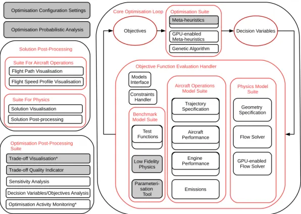
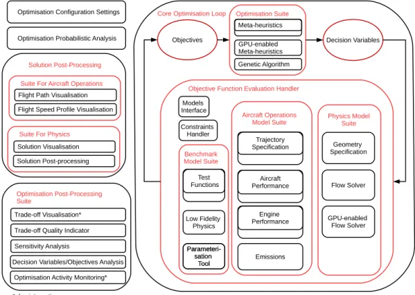
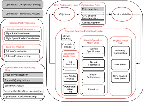
Principles of Optimal Design [61], Systems Engineering and Systems Modelling [56] are employed in the proposed methodology, as outlined in Fig. 1.1. More specic-ally, the methodology is an optimisation methodology, where the aim is to search for improvements in the performance of aircraft trajectories and micro-mixing by altering characteristic parameters. This includes a number of methods and tools, where a combination of them is employed in an instance/application, as required. Any method or the whole methodology can be repeated as many times as neces-sary, so to achieve a certain level of condence. A few of the methods can also be employed during the optimisation process, so as to keep the user as much informed as possible.
The novelty of the methodology lies in the ability to interface with other sys-tems, scalability and use of Graphic Processor Units (GPUs) to accelerate com-putationally intensive algorithms. The technology readiness level [62] of the meth-odology is assessed to be between 1 and 2, and it is possible to reach level 3, where feasibility can be proven by tackling numerous applications.
With reference to the objectives above, the following methods are suggested: 1. Multi-Objective Tabu Search 2 (MOTS2) and related tools and methods will
be developed, so as to support the aforementioned optimisation methodology with the potential to be applied to applications at scale. As a metaheuristic optimiser, MOTS2 is expected to be able to deal with the requirements of real-world applications [55,63]. For scalability purposes, the optimiser will be ported on GPU, so as to be able to handle a large number of decision variables in the future.
2. A ow solver based on the Lattice Boltzmann Method (LBM) will be de-veloped and will be ported on GPU, so as to accelerate the execution. 3. The optimiser will be benchmarked against test function and reference
prob-lems. Furthermore, it will also be compared against a competitive optimiser of the same class and another, so as to identify cases for which it would be suitable.
4. The methodology will be integrated into representative models to study the performance of the optimiser under 2 and 3 objectives.
5. The methodology will be linked to the aforementioned uids solver and will be applied to a reference study, where tools of the same class of optimisation and simulation were used, so as to compare and evidence any performance gains. Optimisation Suite Models Interface Optimisation Post-Processing Suite Physics Model Suite Objective Function Evaluation Handler
Core Optimisation Loop
Geometry Specification
Suite For Aircraft Operations
Flow Solver GPU-enabled Flow Solver Emissions Aircraft Operations Model Suite Aircraft Performance Engine Performance Benchmark Model Suite Test Functions Low Fidelity Physics Optimisation Configuration Settings
Suite For Physics
Parameteri-sation Tool *also interactive Constraints Handler
Optimisation Probabilistic Analysis Objectives Decision Variables
Flight Path Visualisation
Solution Visualisation Parameteri-sation Tool Meta-heuristics Trade-off Visualisation* Trade-off Quality Indicator Sensitivity Analysis
Decision Variables/Objectives Analysis Optimisation Activity Monitoring*
GPU-enabled Meta-heuristics
Flight Speed Profile Visualisation
Solution Post-processing
Solution Post-Processing Genetic Algorithm
Trajectory Specification
Figure 1.1: Abstract Optimisation Methodology
A description of the modules and methods follows, as depicted in Fig. 1.1: Optimisation Conguration Settings: A collection of settings to specify the
optimisation problem and to instruct the behaviour of the optimiser. These are specied to balance between exploration and exploitation of decision space, depending on the complexity of the optimisation problem.
Optimisation Probabilistic Analysis: A method to run multiple instances of an optimisation problem and acquire the generated trade-o, so as to visu-alise and assess the quality of the trade-o over all the runs.
Optimisation Post-Processing Suite: A collection of methods to analyse and interpret the optimisation results following the end of the optimisation, where:
1.3. OVERALL PROJECT METHODOLOGY 9 Trade-o Visualisation: A plotting method to visualise the trade-o, as generated by the optimiser during the execution of the optimisation process.
Trade-o Quality Indicator: A method to numerically represent the qual-ity of the trade-o by processing all the points of the trade-o. It is mainly used for automation (i.e., within the optimiser) and comparison purposes.
Sensitivity Analysis: A method to numerically represent the importance of decision variables.
Decision Variables/Objectives Analysis: A collection of methods to pro-cess and visualise the decision variables, and/or the interplay among the objectives, so as to identify relationships, which would be hard to detect otherwise.
Optimisation Activity Monitoring: A method to visualise the search progress of the optimiser.
Core Optimisation Loop: The main optimisation loop. Depending on the com-plexity, the computationally intensive parts of the simulation ought to be further restructured, so as to run on a platform that could speed up the simulation, such as GPUs.
Optimisation Suite: A collection of optimisers.
Objective Function Evaluation Handler: A collection of handlers, in-terfaces and models (where the decision variables are mapped via simu-lation of the underlying physics and/or business logic to objectives) for the optimisation problem, where:
Constraints Handler: An interfacing method between the optimiser and the Model Suites to detect the operating status of an instance of Model Suite and provide failed values for the objective function(s) in the case of a failure (e.g., when the Model Suite does not return the values of an objective function for a certain combination of decision variables). This is a fail-safe mechanism to protect any unexpected cease of operation of the optimiser.
Benchmark Model Suite: A method to verify the behaviour of an optimiser to compare the ability to generate a trade-o. The dif-ference between the Test Functions and the Low Fidelity Physics is that the former have a well-known trade-o, whereas the lat-ter's trade-o might not be known in advance. The Parameterisa-tion Tool is a module that is required by the Low Fidelity Physics method, as explained in 3.1.7.1.
Aircraft Operations Model Suite: A collection of methods to carry out ATO.
Physics Model Suite: A collection of methods to carry out an in-stance of design optimisation.
Solution Post-Processing: A collection of methods to visualise, process and evidence aspects of an optimisation solution. Normally, this is employed to further analyse a number of solution(s) by using human insight and domain expertise, so as to identify special features that are responsible for the change in objectives and/or assess the quality of the optimisation solutions.
Solution Post-Processing Suite For Aircraft Operations: A collection of methods to visualise aspects of the target ight, where:
Flight Path Visualisation: A snapshot of the ight path, frequently represented as a 2D plot of range vs altitude.
Flight Speed Prole Visualisation: A snapshot of the speed prole of the ight path, frequently represented as a 2D plot of range vs speed.
Solution Post-Processing Suite For Physics: A collection of methods to visualise aspects of the target design by visualising a target geometry and ow features and/or post-analysis the former so as to gain a better insight.
1.4 Outline of Thesis
The remainder of this document is structured as follows:
Chapter2identies limitations of existing methods by reviewing current state-of-the-art tools and methods in optimisation techniques, ATO and micro-mixing studies.
Chapter 3 describes in detail the development and benchmarking of a MOO
algorithm and a prototype uid solver for the purposes of the research. The architecture of the developed systems, implementation details and design decisions are discussed, too.
Chapter 4 presents three optimisation applications to demonstrate the de-veloped tools and methods. First, an ATO application at the climb phase is performed, so as to minimise fuel consumption and ight time. The same method-ology is then applied to a 3-phaseATO, so as to minimise fuel consumption, ight time and gaseous emissions. Third, while investigating for new aircraft technology, the shape of a microreactor is optimised, so as to study its ow mixing and other ow properties that reduce gaseous emissions.
1.5. CONTRIBUTION TO KNOWLEDGE 11 Chapter5summarises the main ndings of the research and recommends future research directions at various levels.
1.5 Contribution to Knowledge
By achieving the aforementioned objectives and identifying current limitations in state-of-the-art methods, the contribution to knowledge follows:
A exible optimisation methodology is devised that can be linked and applied to problems related to ATO and micro-mixing optimisation with 2 and 3 objectives. This is also benchmarked and assessed relative to state-of-the-art techniques in optimisation with known and unknown trade-os. The ability of the methodology to reveal non-dominated trade-os, also with reference to competitive optimisers, in 2 and 3 objectives is additionally demonstrated. The impact of deploying an optimiser on GPUs and carrying out a
micro-mixing optimisation study where the ow solver is deployed on GPUs is assessed in terms of computational eciency and speed up. In the latter case, the quality of the generated trade-o is also compared against a reference study [64].
During this research, software packages (see chapter 3, [65]), and the following technical report and articles were produced:
C. Tsotskas, T. Kipouros, and A. M. Savill. Fast Multi-objective Optim-isation of a Micro-uidic Device by Using Graphics Accelerators. Procedia Computer Science, 51:2237 - 2246, 2015
C. Tsotskas, T. Kipouros, and A. M. Savill. Multi-Objective Tabu Search 2: First Technical Report. Craneld University, 2015, ISBN 978-1-907413-34-6 C. Tsotskas, T. Kipouros, and A. M. Savill. The Design and Implementation of a GPU-enabled Multi-objective Tabu-search Intended for Real World and High-dimensional Applications. Procedia Computer Science, 29:21522161, 2014
C. Tsotskas, T. Kipouros, and M. Savill. Biobjective optimisation of prelim-inary aircraft trajectories. In Evolutionary Multi-Criterion Optimization, volume 7811 of Lecture Notes in Computer Science, pages 741-755, 2013 M. Razzaq, C. Tsotskas, T. Kipouros, M. Savill, and J. Hron. Multi-objective
optimization of a uid structure interaction benchmarking. Computer Mod-eling in Engineering & Sciences, 90(4):303337, 2013
Chapter 2
Literature Review
2.1 Initial Contributions
The concept of ATO had been discussed in [6669], where the trajectory is mod-elled by using optimal control theory. Signicant work in terms of theory, meth-odology, processes and techniques is presented in [68,7078]. All these approaches transform the optimisation problem into another type of problem and employ re-spective methods, usually called direct and indirect methods. However, a prior and deep insight of the nature of mathematics and physics is required so as to obtain a sensible solution by employing the optimal control theory, which cannot be taken for granted when dealing with real-world cases [69], especially in diverse environments. Obviously, the rst action to reduce emissions is to cut down fuel consumption, as was also mentioned in [79], which, as expected, has reduced the negative impact of greenhouse gases.
Optimisation was employed very early to address real-world problems when critical decision(s) had to be made. The nature of real-world cases is such that very frequently multiple and conicting criteria are involved, which leads to using specialised tools and methods. One of the earliest references inMOOcan be found in [80], where cost, sensitivity, stability, risk, and irreversibility and other metrics were considered as separate objectives. Following MOO, the concept of Multi-Objective Decision Making was also discussed in [81], where a decision maker is called to attain more than one goal or objective in selecting the path of action, subject to a variety of constraints forced by the environment, resources and pro-cesses.
2.2 Computational Methods for Aircraft
Techno-logy for Mixing by using CFD
Over the years CFD has been proven as a tool of paramount importance in aviation [82]. It has enabled users to design, to analyse and to support high-performing and cost-ecient commercial transports. The ability to model (both aerodynamic and reactive) ows by using CFD has progressed considerably and changed the aerospace design process, while reducing testing requirements and physical designs at lower cost and risk. Moreover, it is foreseen that using CFD
will contribute critically to performing more environmentally-friendly studies in the next few years [29].
Although there are numerous approaches to improving the technology of exist-ing gas turbine engines [83], there are studies that investigate alternative ways to generate energy such as [27,35,41,8491], which depend on specialised software. The studied devices consist of many dierent components with very complicated geometrical arrangements that challenge conventional tools from the elds ofCFD. Apart from new conceptual devices, conventionalCFDtools are invaluable [92,93], but new tools will be required to make considerable progress [60,93]. These tools are required to perform studies within acceptable time frames, as the current mech-anisms are very time and resource consuming. When a new technology of energy generation in aviation is researched, usually standard tools and methods from the elds of CFD are employed. However, these tend to take considerable wall-clock time. In addition, setting up the case to handle complicated boundary conditions, multi-phase or multi-component ows is usually a very time-consuming task, which requires further processing time to nish the simulation.
When engineering applications require resolving uid interactions in high ac-curacy, the LBM oers an alternative method for CFD instead of using the Navier-Stokes (NS) equations [9496]. More specically, it is a class of cellular automata that can approximate theNS equations to second order with an explicit collision-streaming scheme [97]. It is particularly suitable for problem instances that involve low Mach number ow, mesoscopic ows, complex geometrical ar-rangements and particular boundary conditions. Further studies considerably im-prove LBM's potential and capabilities making it a practical tool for engineering applications [98103]. However, when it comes to LBM, the majority of the im-plemented solutions attempt to simulate a few of the benchmark problems, such as lid-driven cavity ow and others, for instance [104]. LBM is expected to be the next evolution in computational sciences [105]. It is not going to replace traditional
CFDmethods based on NS, but it can be considered as a competitive alternative that can occasionally (e.g., [106]) inuence the generation of new approaches and needs to be further matured.
2.3. ACCELERATING COMPUTATIONAL METHODS OF COMPUTATIONAL FLUID DYNAMICS15
2.3 Accelerating Computational Methods of
Com-putational Fluid Dynamics
Multi-disciplinary approaches that involvedCFDdid not change as rapidly as they could, while High Performance Computing (HPC) has rapidly evolved [29]. Phys-ical modelling could not accurately predict the important ow features, as the geo-metries became more complex and the software became even more sophisticated, which gave rise to multi-disciplinary simulations. Furthermore, conducting high-precision studies is of paramount importance when researching on combustors that use hydrogen, but they are also computationally intensive [107]. Consequently, the time required to run aCFDsimulation will impede to scale up the problem to sim-ulate a more detailed aircraft model as the computational workload would increase and more complicated geometrical arrangements should be handled.
In general, adopting alternative software and hardware is still at an early stage before it becomes well established and is an ongoing topic widely discussed in many scientic conferences [108,109]. Big vendors and institutions from the elds of computer modelling either have focused their eorts to develop tools that make use of that technology or they have already acquired them [110,111]. Others have integrated them with their processes or have adopted them accordingly, such as [112].
The advance of recent GPUs in terms of higher processing throughput, larger memory bandwidth and their faster in-between inter-communication capabilities greatly contributes to the evolution of new tools and methods. The hardware includes highly parallel, many-core and multi-threaded processors and many hier-archical memories. In addition, Compute Unied Device Architecture (CUDA) is a programming language that has the ability to access GPUs' hardware and has reached a level of maturity, where programming is more exible and robust than ever before. Hence, computationally intensive applications can run more ef-ciently even on very large scale problems [113]. Simply, it provides exibility to directly and easily manipulate various levels and types of ne computational resources onGPUs. Due to the low overall cost and high computational eciency, they suggest a decent alternative computational architecture that can suciently cope with the requirements of scientic applications, which increasingly require even more computational power [29,114,115]. Computationally, GPUs also have great cost-benet: Their low energy consumption for the attained computational speed inspired the creation of the performance metric proposed in [116], where the computational power is combined with the energy required for performing a simulation.
The LBM is one of the alternatives with great potential for the future of avi-ation and a great t for computavi-ational platforms based on GPUs, because it is
an algorithm whose logic is very well aligned with hardware operation of GPUs, as explained below and in greater detail in subsection 3.3.1. By denition, the concept of LBM is a memory-bound algorithm, which provides a good t for the
GPU architectures. Given a computational environment with many processors,
GPU-enabled LBM codes could potentially run considerably faster without com-promising accuracy [104,117129]. The execution of the LBM algorithm can be signicantly accelerated when running onGPUs, for instance [123]. In general, the
GPU-enabledLBMis a competitive counterpart in terms of both accuracy and ex-ecution speed. So far, signicant exex-ecution speed-up and faster convergence rate have been achieved. Furthermore, for a relatively small computational domain it has the potential to perform a real-time simulation.
Available computational power and low cost will be a considerable factor in the evolution of aviation [93]. Employing alternative computational architecture on
CFD-based applications can be an intermediate step towards the next generation ofHPC and computational methods [29]. As already mentioned, there are several applications where GPUs have been proven useful in accelerating the execution of sub-system(s) for the purposes of aviation and many more are expected in the future. However, only a few of them are compared against real-world data and even fewer are coupled with other systems (e.g., [130]).
As usual, when implementing an HPC application, the most challenging is-sues are instruction-level-parallelism, memory management, power management, algorithmic dependencies, hardware dependences, data dependences, and other de-pendencies. Therefore, it is critical to design and develop the application following the principles of object-orientation to minimise any complications and allow for future extensions. However, as pointed out in [131], porting and upgrading every possible application toCUDAdoes not pay o for the attained speed-up. Another challenge lies in the eld of intercommunication with other systems, which depends on legacy software and impedes coupling.
The performance of GPUs on many applications has inspired the creation of supporting tools and projects for even greater achievements. Other projects at-tempted to simplify and unify the implementation of applications for sustainable development [132]. Two applications in the elds of structural mechanics [131] and uid mechanics [133] not only demonstrated increased computational per-formance, but they also introduced novelty in memory management (for instance, memory-fetching) and mixed-precision arithmetic, respectively. Similar projects are required so as to establish the use ofGPUs on engineering applications.
For the purposes of advancing applications of aviation technology by usingCFD
methods, high-delity simulation technologies ought to evolve, which could poten-tially contribute to the achievement of future environmental goals [29]. More spe-cically, CFDmethods should evolve along with HPC and should take advantage
2.4. OPTIMISATION APPLICATIONS BY USING CFD 17 of modern HPC infrastructure, where GPUs are very strong candidates. Several studies attempt to adapt applications ofCFDwith nite volumes to run onGPUs, such as [130,134], but compared toLBM, the obtained speed-up is not very satis-factory. Successful work in this direction has been presented in [117,119], where signicantly high performance was achieved. Even in more advanced applications, such as [135], LBM can be computationally faster. From a theoretical point of view, when studying devices at micro-scale Knudsen number (Kn) rises and the NS equations cannot be used [136,137]:
Kn =
λ
L (2.1)
where λ denotes the mean free path of a molecule, and L is the characteristic
length. Moreover, the eect ofKnwill be very important when the application will
be capable of resolving the phenomena of heat transfer, as discussed in [138,139]. Simply, accurately predicting the characteristics of any micro-device that depend on temperature is a very challenging task. Hence, using the NS equations is not the best approach.
2.4 Optimisation Applications by using CFD
When it comes to designing technology for the future of aviation, there are sev-eral studies that carry out optimisation by using tools from the eld of traditional
CFD. Nevertheless, using LBM was rst introduced in [64,137] and these studies extend this work. However, the elapsed wall-clock time and resources required to complete such an application are not satisfactory for engineering applications. Specialised and expensive infrastructure is required, which is accessible to very specic organisations and users. Hence, the utilisation of resources, the cost of delay (with respect to the time required to complete one case) and the accessib-ility ought to be improved so as to scale up and be more practical. To the best of the author's knowledge, this is the rst time such operational constraints are considered and these should be combined with a exible software architecture so as to link with other applications, too.
An instance of computational intelligence in optimisation methodology can be found in [133], where a two-layer hierarchical optimisation code operates with variable precision. The lower level handles computations in single precision while exploring design space. Following a nite threshold, the optimisation algorithm switches to the double precision mode for the most promising regions, where sig-nicant accuracy is required. This strategy follows the fundamental principles of
CUDA, where single precision operations are executed faster, so as to eectively utilise the computational eciency of GPUs. As a compromise, mixed precision
could be used: On each equation, the left-hand-side and right-hand-side parts are calculated with a single and double precision, respectively. The latter presen-ted the highest ratio of precision for computations, a very reasonable metric for engineering applications. The optimisation algorithm can also operate in both precision modes. It is important to mention that a few scientic references were found that combine design optimisation along with GPUs-enabled CFDtools and methods (e.g., [133]). However, none was found to be applicable to micro-mixing optimisation studies.
2.5 Accelerating Optimisation Methods
Based on the author's experience, multi-objective optimisers might degrade in performance because of the number of decision variables, the number of objective functions, the number and type of constraints. Also, in terms of process life cycle, the elapsed time to evaluate an objective function is also important, as compu-tationally intensive objectives might need to be modelled [140], so as to speed up the optimisation. As pointed out in [93], the large number of variables (more than 4000) involved in a singleCFDsimulation while employing multi-disciplinary objectives dramatically increases the problem size. In addition, it is clearly men-tioned in [141] that alternative parallelisation techniques (e.g. usingGPUs) should be employed in the future. Hence, employing GPUs to accelerate the execution of the algorithm is a viable approach and further developed in subsection3.2.
The potential of GPUs has also been demonstrated in optimisation applica-tions. First, an instance of single-objective tabu search in Mixed Integer Program-ming was presented in [142]. Specically, the quadratic assignment problem for more than 30 items was optimised, achieving higher throughput. The greatest gain was noticed for the pair-wise exchange and initial cost calculation routines, which are the most computationally intensive parts. Comparative to Central Processor Unit (CPU) implementation, 20 to 45 times faster results derived by porting the same code in CUDA, while the same results were obtained as if the code ran on a computational cluster. Algorithmic-wise, neighbourhood exploration and con-current regions searching are mainly favoured. Still, minimising communication between CPU and GPU is a critical factor, which is alleviated in most recent generations. Secondary problems concerning the parallel tabu search are: unique search space allocation, threads operational overlapping, promising regions explor-ation and memory control. A variant of native multi-objective tabu search that operates on GPUs has been designed and has been implemented with the inten-tion to be used on real-world applicainten-tions with increased problem size. Many cost functions for dierent combinations of decision variables can be evaluated at the same time because of the fast throughput of GPUs. This capability will enable
2.6. OPTIMISING AIRCRAFT TRAJECTORIES 19 users to run cases with thousands of variables within a reasonable time frame.
2.6 Optimising Aircraft Trajectories
The environmental impact can be minimised considerably by revising the ATM
procedures such as lower cruise speed, arrival management and departure manage-ment, the continuous descent approach, noise preferential routes, noise abatement procedures and others described in [143]. A similar concept to ATOwas presented in [144,145]. The objective was to design an aircraft to y on pre-specied routes. Th
![Figure 3.14: Demonstrating the Performance of NSGAMO (in the Plots Re- Re-ferred to as NSGAMO3) on ZDT3 Against State-of-the-art Optimisation Al-gorithms [220]](https://thumb-us.123doks.com/thumbv2/123dok_us/809071.2602293/98.892.167.785.158.520/figure-demonstrating-performance-nsgamo-plots-nsgamo-optimisation-gorithms.webp)
![Figure 3.15: Demonstrating the Performance of NSGAMO (in the Plots Re- Re-ferred to as NSGAMO3) on ZDT6 Against State-of-the-art Optimisation Al-gorithms [220]](https://thumb-us.123doks.com/thumbv2/123dok_us/809071.2602293/99.892.112.733.148.546/figure-demonstrating-performance-nsgamo-plots-nsgamo-optimisation-gorithms.webp)