Designing for an Emergency
– Developing Support for a Collaborative
Time-Critical Environment
Lucien Bokouka
NADA
Numerisk analys och datalogi Department of Numerical Analysis
KTH and Computer Science
100 44 Stockholm Royal Institute of Technology
SE-100 44 Stockholm, Sweden
Designing for an Emergency
– Developing Support for a Collaborative
Time-Critical Environment
Lucien Bokouka
TRITA-NA-E03161
Master’s Thesis in Computer Science (20 credits)
within the First Degree Programme in Mathematics and Computer Science, Stockholm University 2003
Supervisor at Nada was Kjell Lindqvist Examiner was Stefan Arnborg
Abstract
In safety and time critical environments such as emergency call centres it is impor-tant for the users of such systems to be able to perform their work as quickly and efficiently as possible. In order to successfully develop such systems the developers should use methods such as interaction design, which is the central theme in this thesis. Methods such as interaction design become increasingly important for devel-opers, as more and more software today are made more complex.
This Master’s project has consisted of analysing the work practice and coordinative work of the operators at SOS Alarm, mainly concerning the handling of emergency calls and documentation of a case.
This project has resulted in designing, implementing, and evaluating a prototype ap-plication for the coordinative work of the operators at SOS Alarm based on discus-sions of a series of improvements according to the way the operators actually use the current system.
Keywords: Interaction design, usability, coordinative- and time-critical work.
Referat
Design för nödsituationer
– utveckling av stöd för en kooperativ och tidskritisk miljö
I säkerhets- och tidspressade miljöer som larmcentraler är det viktigt för användare av ett sådant system att kunna utföra sitt arbete så snabbt och effektivt som möjligt. För att utveckla sådana system på ett framgångsrikt sätt måste utvecklare använda metoder såsom interaktionsdesign, vilket är det centrala ämnet i den här rapporten. Metoder som interaktionsdesign blir mer och mer viktiga för utvecklare eftersom många moderna program är mer och mer komplexa.
Detta examensarbete består av en analys av SOS Alarms operatörers arbetssätt och samarbete, huvudsakligen kring hantering av SOS-telefonsamtal och dokumen-tationer kring dessa.
Arbetet resulterade i utformning, implementering och utvärdering av en applika-tionsprototyp skapat för att förbättra SOS Alarm-operatörernas samarbetssystem. Prototypens kravspecifikation är baserad på förslag av förbättringar i enlighet med hur operatörerna använder det nuvarande system i bruk idag på SOS Alarm.
Acknowledgments
First I would like to thank my supervisor Maria Normark for her support and help she has given me in this project. I would also like to thank Máire Quigley and my big sister Christina who gave me a lot of support and help specially with correcting proofs.
I would also like to thank my mother for the moral support and Sanshin Karate and Iê Capoeira for the spiritual and emotional support.
Contents
1 Introduction ...1
1.1 Background and motivation...1
1.2 Research questions...1
1.3 Research scope and limitations...1
1.4 Outline for the remaining chapters ...2
2 Human Computer Interaction – Background ...3
2.1 To develop usable systems ...3
2.2 Interaction design...7
2.3 Project Methodology ...8
3 The Emergency Centre Domain ...10
3.1 Work description of the SOS operators ...10
3.2 Analysis of the work performed by the operators at SOS ...14
3.3 Summary of the main issues we wanted to address...17
4 The Prototype Design Process...18
4.1 Procedure for creating the requirements...18
4.2 System Requirements ...20
4.3 Interface design...20
5 The Technical Elements of the Prototype ...27
5.1 Choosing programming environment ...27
5.2 Designing the database ...28
5.3 Application design ...30
6 Expert Evaluation of EmCoord ...32
6.1 Main issues that were brought up ...33
6.2 Comments ...35
7 Discussion...36
7.1 Summary...36
7.2 Future Work...37
References...38
Appendix A – System requirements...39
Appendix B – Paper sketches and screen shots...49
1 Introduction
1.1 Background and motivation
In safety and time critical environments such as emergency call centres it is impor-tant for the users of such systems to be able to perform their work as quickly and efficiently as possible. In order to successfully develop such systems the developers should use methods such as interaction design and be well versed on how the human system (e.g. vision, cognition, memory) works. In recent years interaction design has grown in popularity in the human computer interaction community, especially since computerised machines are leaking in into every corner of our lives and since more and more software today is becoming more complex.
This thesis has its basis in studies performed by the Royal Institute of Technology (KTH) and Blekinge Institute of Technology (BTH) on the prospect of developing a new system for SOS Alarm. The idea with the new system is that the coordination of work is not limited locally to each centre, but can be remotely administrated be-tween different SOS centres. These studies have shown that there are numerous potentially critical aspects concerning coordinative work and case documentation. The objective of this Master’s project has been to analyse and develop improve-ments of support for the coordinative work of the operators at SOS Alarm when handling emergency calls and dispatching emergency units such as ambulances. I also analysed the current system in use today at SOS and how it supports the coordi-nation of work. I have mainly focused on interface and interaction design issues concerning documentation of a case. I also created a conceptual prototype model where I used the new features discussed in this thesis.
1.2 Research questions
The aim of this project was to investigate how to better support the work practice in answering emergency calls and dispatching units for the operators at SOS Alarm, and also how to improve the coordination issues amongst the operators.
1.3 Research scope and limitations
In this thesis I have focused on analyzing the part of the emergency case process that deals with documenting emergency cases and allocating resources to a case. It was not my aim to develop an entire system for operations at SOS Alarm, but rather to propose a conceptual prototype model. The emphasis of this thesis therefore lies on user interface, interaction design and database management.
1.4 Outline for the remaining chapters
Chapter 2
This chapter provides the theoretical background for this thesis. Here the terms usability and interaction-design are explained and how they should be used when developing an application.
Chapter 3
In this chapter I evaluated the current system in use today at SOS Alarm with the help of studies made by Normark, the Work Practice Laboratory at Blekinge Insti-tute of Technology in Ronneby and SOS Alarm.
Chapter 4
In this chapter I explain how the design process for the prototype was performed in this project, including compiling a set of user requirements and drawing graphical user interface sketches.
Chapter 5
This chapter contains the technical element of the prototype application, such as which programming environment and database model I chose and why.
Chapter 6
This chapter contains the evaluation performed on the prototype application by two interaction design experts together with some of the main issues that where ad-dressed.
Chapter 7
This chapter contains a summary of what was done in this Master’s project together with discussion for future work.
Chapter 8
This chapter contains the references used in this paper.
Appendix A
This appendix contains the whole user requirement for the prototype application.
Appendix B
This appendix contains screenshots of the prototype application versus drawings made in the development stage.
Appendix C
2 Human Computer Interaction – Background
In this chapter I will define the term usability and describe some of the properties that a user has, sometimes referred as the human system, which should be taken into account when designing usable systems. I will also talk about the law of grouping and how good use of these laws can help the user to understand an interface. Also the term interaction-design will be explained and why it is increasingly important to incorporate interaction-design in a software development process.
2.1 To develop usable systems
As machines and computers leak into every corner of our lives it is increasingly im-portant to make the software that interacts with the user more enjoyable and easy to use. According to the Usability Company [6], usability first emerged as a result of the intensive research into the use of more advanced technology during the Second World War. It was realised that the adaptation of machines to the human operator increased human-machine reaction, speed and performance. The science soon spread into the field of telecommunications and finally computers.
In recent years there has been a developing concern for usability issues in the Hu-man Computer Interaction community. In order to develop usable products it is essential to understand what usability means. Once we have gained insight into what usability is we can address the question of which proceedings to use in order to achieve usability. The ISO definition of the term usability (ISO 9241:11) is as fol-lows:
“Usability is the extent to which a product can be used by specified users to achieve specified goals with effectiveness, efficiency and satisfaction in a specified context of use.”
The terms effectiveness, efficiency and satisfaction is defined as:
Effectiveness: “Measure of the accuracy and completeness of the goals achieved”.
Efficiency: “Measures of the accuracy and completeness of goals achieved rela-tive to the resource (e.g. time, human effort) used to achieve the spe-cific goals”.
Satisfaction: “Measure of the comfort and the acceptability of the work system to its users and other people affected by its use”.
In Ottersten & Berndtsson’s book Användbarhet i praktiken [10] the authors de-scribe usability as a quality-in-use property in interactive products, i.e. products that a user interacts with. According to them, a product has a high degree of usability when it fulfills the goals of the users and customers.
They argue that in order for a product to be usable, the following three aspects must be taken into consideration:
1. The user.
2. The context where the product is used. 3. The benefit the product is expected to give.
2.1.1 The user
Ottersten and Berndtsson describe a user as a collection of properties that they call the human system. The human system properties are divided into two groups; the general properties, such as vision, memory and cognition; and the specific properties within a user-group, i.e. knowledge, values, attitudes and expectations. They also argue that knowledge about how the human system works is necessary to perform evaluations and interaction design.
Furthermore they explain that we are able to see because the eyes take in a flow of impulses that is translated into information. With our sight we are able to register information very fast and automatically. Our brain quickly filters out information that is regarded as unnecessary1. The eyes are always looking for a pattern; when we look at a picture, the eyes sweep across it in an irregular way and try to determine what is essential, what is background, what is background noise and try to find what its form is.
Ottersten and Berndtsson also discuss grouping, which is an essential feature of the way we perceive the world, or how we tend to interpret a visual field or problem in a certain way. The main factors that determine grouping are:
• Proximity – how elements tend to be grouped together depending on their closeness.
• Similarity – how items that are similar in some way tend to be grouped to-gether.
• Closure – how items are grouped together if they tend to complete a pattern. These factors are called the “laws of grouping”, the term was first conceived by a group of German Psychologists called Gestalt Psychologists.
The law of proximity states that objects near each other tend to be seen as a unit. It is important to keep this law in mind when designing print and web-based materials. Focus should always lie on how the intended audience will interpret the graphics used. This is especially important in cases when the image plays a vital role in the ability to interpret the message behind it. According to this law, the arrangement of dots in Figure 1 is seen not as a set of rows but rather as a set of columns. We tend to perceive items that are near each other as groups.
1 Recent studies by Martin Ingvar (Karolinska Institutet) on Cognition show that as much as 60 % of
the information received by our eyes is filtered out by the time it reaches the brain. As a curiosa, this number is as high as 99,9 % if you take into account all our senses.
Figure 1. The law of proximity.
The law of similarity states that objects that are similar tend to be grouped together. In Figure 2, organization of vertical rather that horizontal lines can be seen because of the similarity law of grouping.
Figure 2. The law of similarity.
When we are presented with unbound figures such as in Figure 3, we group the pieces to see an entirely bounded figure. The dotted circle below is completed in our minds. We see an imaginary bound circle. This is the law of closure.
Figure 3. The law of closure.
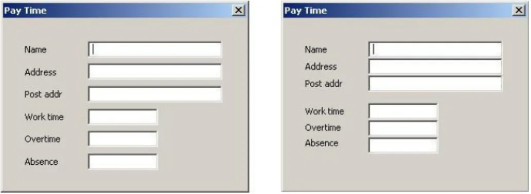
Ottersten and Berndtsson argue that grouping is a very powerful technique when it comes to creating unity between fields. Fields that are placed near each other are interpreted as logically and functionally related. If this is done in a well thought-out way, the effort of interpreting the image is reduced. In Figure 4 two sample GUIs are presented, one that is not grouped and one that is grouped.
Figure 4. In order to help the user process information, groups of information are created. They further explain that we have three types of memory:
• Sensory memory – that acts as a buffer for stimuli received through the senses (vision, hearing, touch, smell and taste).
• Short-term memory – that acts as a scratch pad for temporary recall of the information under process.
• Long-term memory – that stores selected information and afterwards recalls and re-processes impressions. Other information is filtered out.
When designing GUIs it is important to remember not to overwhelm the user with unnecessary information. S/he should be able to have a good overview of the system and should be able to keep the information presented in the short-term memory. In that way the user can be more productive.
The human brain always tries to find patterns so that the process can be automated, which in turn leads to diminished effort. When developing interfaces it is important to help the user find a pattern of how the product is working. A finished pattern can never be conveyed since it is created in the users’ brain. However, the interface can
help the user in the process of creating patterns, especially if the design has a good overview and is consistent.
2.1.2 The context of use
When developing a product, Ottersten and Berndtsson argue that it must be adapted to the right context of use. A context of use is the situational factor that influences the use and usability of a system, including:
• Environmental factors (physical conditions such as space, time, temperature, noise).
• Organizational factors (social network, management and organizational pres-sures, and work processes).
• Technical/system factors (network connectivity, system configuration, sys-tem stability).
• Broad social factors (cosmesis, family conflicts, career aspirations, economy, ethical standards).
2.1.3 The benefit of the product
The product is supposed to bring economical profit to the supplier or advantage to society in some form. In addition, it must also be beneficial to the user of the prod-uct, e.g. render the working process more efficient, simplified or made more enjoy-able.
2.2 Interaction design
A computer-designers job is to design a system with the right functions to enable users to perform their job more easily and at the same time enjoy using it. There are two common ways to do this successfully in the field of human computer interaction (HCI), data or process-centric design, and user-centric design, also known as inter-action design. The goal with process-centric design is to exchange man with machine in those fields where the machine gives a higher performance. User-centric design is about designing products to facilitate the interaction between man and machine.
In Alan Coopers book The Inmates are Running the Asylum [1] he compares the two methods, interaction design and process-centric design that he calls “interface de-sign”. He argues that interface design, which is the “old-school” way of designing software, is first to develop the code and most of the software behavior and then ‘slapping’ on an interface. He draws the resemblance to putting an Armani suit on Attila the Hun. He will still behave in the same way, the difference is that he will look ‘nice’ doing it.
However, interaction design is embedded in every step of the development process and can affect the behavior of the program and adapt it to suit the needs of the user. Alan Cooper’s book has been a source of inspiration when designing the prototype user interfaces. While large parts of this book consist of examples and motivation to convince the reader that a user centered design or interaction design should be employed, it also contains concrete strategies that can be applied in a user-centered design process.
Cooper describes the psychology of the user and tries to describe what motivates the person who will use the application. He uses the terms task and goal, where the goal is what the user wants to accomplish with the interface and the tasks are the steps needed to get there. Cooper argues that applications should focus on solving the user’s goals and not the tasks.
The central questions Cooper asks are too important to ignore: Are we making users happier? Are we improving the process by which they get work done? Are we mak-ing their work hours more effective? Plainly, he asserts that the goal of computer usage should be “not to make anyone feel stupid.” Our distance from that goal rein-forces the need to rethink entrenched priorities in software planning.
Another term presented in this book is cognitive friction. The term is used as an explanation as to why many people have problems using computerized devices compared to traditional, mechanical devices. The mechanical device provides visual
and audible feedback on its operation, if the device has buttons, they will not sud-denly disappear or move, their functionality always remain the same, and they pro-vide tactile feedback when pressed. A user interface on a computer screen on the other hand does not need to follow such physical rules and often does not. Interfaces that break these rules create cognitive friction. Such interfaces become harder to use since they do not follow rules that apply outside the computer.
An important part of Cooper’s design process is to create user profiles, called per-sona. These profiles are meant to represent the typical users of the application and can contain detailed information such as their name, a short résumé and a photo-graph. All of this aids the designers to treat this persona as a real person and bears them in mind when designing the user interface.
After having created a number of different personas, Coopers selects one of them as the primary persona, the one that the application should be developed for. This per-sona is chosen in such a way so that in designing the application specifically with this user in mind the application will be acceptable for all personas.
2.3 Project Methodology
2.3.1 Literature review
The main literature review was performed in the first stage of this Master’s project, to familiarise myself with earlier research done on the subject. The literature review was comprised of two fields: usability/interaction-design and Human Work studies of the environment in which operators at SOS Alarm works, by researchers2 at Blekinge Institute of Technology.
2.3.2 Field study
After reading the Human Work studies of the operators at SOS Alarm a field trip was made to the Stockholm centre. This was done to gain additional knowledge and insight into how the operators perform their work, what the current interface looks like and how the operators interact with each other, with the system and with the emergency units.
2.3.3 Prototype development
When developing the prototype, I have used a mixture of Rational's Unified Process and interaction design. Interaction design cannot be used single-handedly when developing a software product, since interaction design is a tool for determining the behaviour of the product, it must be used together with another software developing process. Rational Unified Process is used by many software engineers today when developing software products. This process however, is a pure process-centric design mechanism. Therefore by combining the two one gets a powerful method for developing robust software with good interaction.
2 Maria Normark [9] and [5], Mårten Pettersson [12] and [5], Bo Helgeson [5], Jenny Lundberg [5]
2.3.4 Prototype evaluation
Here I have used the method of expert evaluation presented in Ottersten and Berndtsson’s book [10]. An expert evaluation can be performed at any stage in the development process and is performed by an interaction designer, but not the one responsible for the design of the product to be evaluated. An expert evaluation is useful for finding usability problems such as unclear or confusing interaction, incon-sistency in the interface, design flaws and so on.
3 The Emergency Centre Domain
In this chapter, I evaluate the current system in use today at SOS Alarm after a field trip to SOS Alarm in Stockholm and with the help of studies made by Normark [9], the Work Practice Laboratory at Blekinge Institute of Technology in Ronneby and SOS Alarm [5].
3.1 Work description of the SOS operators
In this section I will describe the work performed by different operators at the SOS Alarm centre in Stockholm. Most of the material presented here is referred from Normark’s study [9] Using Technology for Real-Time Coordination of Work: a study of work and artefact use in the everyday activities at SOS Alarm. In this pro-ject I have worked closely with Normark and during our many meetings and discus-sions she has provided me with many insights into how operators at SOS Alarm conduct their work from her first hand personal experience. Availing of her expertise has proven to be of great value in this project. I also describe the field trip made to the SOS Alarm centre in Stockholm.
3.1.1 The ecology of the workplace at the Stockholm centre
At the Stockholm centre, about 15 operators work together daytime. Six or seven work with receiving 112-calls only, three operators are responsible for ambulance dispatch, one operator is the shift leader and three operators work with commercial services. Their placement can be seen in Figure 5. Moreover, the division of labour at the Stockholm centre is statically divided between the 112 receivers and the ambulance dispatchers. There is a lot of verbal communication between the 112 receivers and the dispatchers. However, due to the fact that it is rather noisy in the room, the 112 receivers and the dispatchers do not often overhear each other’s work. However, they can see each other and thus can judge if the other is busy or not.
The visit to the Stockholm centre was relatively short considering the complexity of the work performed by the operators. For special educational purposes3, SOS Alarm grants visitors access to their facility. We were granted a standard two-hour tour of the facility, where we could sit beside different operators and observe their work in progress and also ask questions.
The centre is highly protected by different types of security measures. At the recep-tion visitors are given a special nametag that grants security access to the lower lev-els where the operators reside. We were also accompanied by authorised personnel to access the elevators. The actual control centre is situated 37 meters under ground and is classified as a shelter.
Upon entering the control-centre we could overview the whole office landscape with about a dozen operators sitting at their stations. Each station was comprised of a table with two large display screens, a customised keyboard, a mouse and a headset. We were given a headset so that we could listen in on the various incoming calls and the communication between the dispatcher and the emergency units.
In the two hours I spent there I was not able to fully grasp how the operator inter-acted with the system. The most obvious reason was that the operators knew the system well and were able to perform many actions very quickly. In other words I was not able to keep up. In case of a serious emergency, the operators must be able to respond quickly and send out units. To that end, they are trained to perform their duties as quickly and efficiently as possible.
However, even though I was not able to follow every detail of their interactions with the system, I got a good picture of how the system works as a whole. I also got a good notion of how the operators communicate among themselves, i.e. receiving operator and dispatcher. For a detailed description of the work practice I looked at the Human Work studies by Normark and Blekinge Institute of Technology.
3.1.2 The CoordCom System
In Normark’s study, Using Technology for Real-Time Coordination of Work [9], she thoroughly describes the work practice performed by operators at SOS Alarm. The operators’ main tool is the computer-aided dispatch system called CoordCom. Through the CoordCom the operators handle all forms of communication: telephone when answering incoming emergency calls, fax, mobitex which is a text-based communication system used between the units and the SOS centre, also used for automatic alarms, and radio for direct communication with emergency units such as ambulances. The CoordCom is connected to two different databases; a local data-base for each centre where all action plans, ongoing cases, resources, contact infor-mation is stored. It is also connected to a central database that is used for accessing telephone subscription records to generate address information about the caller. The CoordCom is handled by a specially made keyboard that gives access to certain functions, for example answering an emergency call. There is also a mouse and a
3 Such as ambulance drivers, nurses, new operator recruits, and Human Work field studies such as the
headset that the operators use for communication. The CoordCom also supports recording and documenting of the different cases (in the local database), both emer-gency and commercial alarm services that SOS handles. Finally there is a “map computer” that shows the location of the emergency units with the help of a GPS system. The GPS system tracks all units and displays their location on a digital map. This system is very useful both for giving driving instructions and to pick the closest ambulance to the accident.
Normark also describes the usage of large pull-down maps that look like shades when an address is not found in the map computer. These maps show the important ambulance areas that the operators need to put in CoordCom in order to single out available ambulances. The maps are used to locate the incident area, to give driving directions to the units and also to decide the area code that should be assigned to the case. The area codes are very important for the selection of the right ambulance. For each area code, decisions are made on which ambulance station should take the case.
3.1.3 The answering operator
Normark noticed that when answering emergency calls, the first thing the operator tries to decide is whether it is a case for SOS Alarm or not. SOS estimates that almost 80 % of the incoming 112 calls are without a valid reason4. Hence it is very important to quickly determine if it is a valid emergency call or not to prevent valu-able time and energy to be wasted, when it can better be used helping people who require genuine and immediate attention.
When the validity of the call is established the operator begins to interview the caller and tries to gather and document as much information as possible about the incident. The first two things to determine is what has happened and the location of the inci-dent. The operator must then decide on the priority that should be assigned to the case on a scale of one to four. Priority 1 is the highest these are life-threatening cases. In a priority 1 case the operator must be able to dispatch a unit within 90 seconds of answering the call.
The operator starts off with a ‘Basic Form’ where the phone number of the caller and a list of current cases at the centre are automatically shown. By accessing the telephone subscription database automatically, CoordCom will generate an address from the phone number. If a call is made from a mobile phone, CoordCom will not generate an address, and the operator has to rely on the information given by the caller alone. Before entering a case into the system, the operator checks if a similar description has already been recorded in the list of current cases to avoid cases from being recorded more than once.
If the case already exists, the operator simply clicks on that case in the list of current cases and all the information about that case is presented to the operator. If it is a case that is not in this list, the operator attaches a ‘Resource Form’ to the Basic Form. The Resource Form is either of 6 types: rescue, ambulance, service, traffic accident, doctor or other. Furthermore, the operator can choose a categorisation from
4 Invalid reasons meaning prank calls, wrong number calls, calls aimed for the phone number
a list within each Resource Form. This categorisation is used by the CoordCom sys-tem to generate an action-plan. There is also an area code which is of importance, because CoordCom will show a list of available ambulances in that area zone. This code is generated by the address of the accident. In hesitant cases, the operators work with large paper maps where the zone borders are detailed. While working on the ‘what and where’ questions, the operators also write information about the per-son in question, earlier problems, driving directions and so on.
As soon as it is established that it is a priority 1 case, the answering operator asks a dispatch operator to co-listen or ‘listen-in’. In that way, the whole process of an-swering a call to dispatching emergency units is made faster. The co-listening re-quest is done through the CoordCom, and as soon as the dispatching operator has acknowledged the request, s/he will usually show this by saying, “I am with you”. In order for the dispatch operator to quickly understand what is going on, the answer-ing operator usually repeats the information, e.g. “so your father has fainted and he is not reacting when you try to shake him?” In this way, the answering operator can calmly continue to gather information from the caller while the dispatch operator directs appropriate units to the correct address. Normally it is sufficient for the dis-patch operator if he has a priority, a rough description of the accident, and a geo-graphical location. If there is a lengthy driving/parking direction, the operators usu-ally explain it verbusu-ally.
3.1.4 The dispatch operator
The dispatch operator keeps the unit(s) up to date with new information as soon as it is acquired either by radio or mobile phone. The dispatch operator’s view consists of a Telematic part, a Resource Form and a list of available units on duty for a specific area. Each row in the list of available units contains information about the name of the unit, its latest reported status, when that status was sent in, priority status of that specific unit, which area it is in and a note about the type and a description of the unit, e.g. “Day” or “Transport”. The status for a unit is generated by the CoordCom system receiving mobitex messages from the unit. These statuses can be for exam-ple: “we have received the call and are on our way”, “soon arriving”, “at the acci-dent site” or “the patient is now in the ambulance”.
The dispatch operator contacts the different units, first by radio where s/he informs the unit briefly about geographical location, kind of incident and priority. After assigning a task to a unit, the unit has about two minutes to acknowledge the mis-sion. The acknowledgement by the paramedics or rescue team can either be done by contacting the SOS by radio, calling through the telephone or by sending a text mes-sage through mobitex. If the unit fails to acknowledge the mission the operator will try to contact it through mobile phone or by radio.
It is interesting to note that operators often call the unit before sending the mobitex message or ask about it when the unit calls in. Normark speculates that it is because they want to make sure that the information reached the units, due to the fact that the mobitex system is relatively new. Also it may serve as a good way to maintain the goodwill between operators and paramedics by the use of verbal communication.
When the dispatch operator receives the status from a unit through mobitex, it looks like an incoming call containing a text message. When the acknowledgement is received the operator sends a mobitex message containing all the information about the case.
Once the dispatching operator has completed directing units to an emergency site, receiving status reports, either through mobitex messages or through telephone calls, he continues monitoring the development of the case. If several operators are in-volved, i.e. both rescue and ambulance dispatcher, the operators communicates the status reports that they have received from each other. The first unit that reached the incident will give a status report and together with the operator decide if the right service has been sent to the accident. All new information is documented by entering it into the Resource Form and is thus accessible to the other controllers. New infor-mation may mean that new units are selected and dispatched. It can also mean that some of the units sent are unnecessary. When monitoring a case, the dispatch operator is working alone, but other operators may verify the status reports from the units.
Note that the operators are not responsible for the actual rescue, just to send the proper units. This means that the operators usually are not informed of the outcome of the actual incident. The case is closed as soon as the units have reported the status Ready (for a new assignment).
3.2 Analysis of the work performed by the operators at SOS
In this section I will proceed point by point and discuss improvements5 in regard to the work practice of the operators at SOS Alarm as described in the preceding sec-tion (3.1).
3.2.1 SOS centres
Today all the different centres have their local database where they store information about all the different cases at that centre. One of SOS Alarm’s aim is to connect all the different centres so that they all will share a central database. In this way a centre that is very busy and cannot receive any more calls can redirect the calls to another centre, regardless of geographical proximity to the caller. In order to implement these changes, one needs to design a distributed database. More will follow about database design in paragraph 5.2.
The map computer currently needs a lot of improvement. This is mainly due to the fact that this system is relatively new and a lot of features have not yet had time to be developed. The operators at SOS Alarm still use large pull-down maps to help them see ambulance areas, to locate incident areas, to give driving directions to the
5 To improve a very complex system is very difficult as there are many aspects than can be
overlooked. By improvement, in this context, I mean to improve what can immediately be seen. For example, if an operator has to push three different buttons to answer a call, the immediate reaction could be to change this procedure so that only one button needs to be pressed. However, since the coordinative work at SOS is very complex, one cannot foresee all the contingencies. It can later be proven that the ‘improvements’ discussed here are not working at all. Therefore the word improve in this case should be taken mildly and not as an absolute.
units and to decide which area codes to use. All these procedures can be imple-mented as features in the map computer. However, the map computer problem is outside the scope of this Master’s project.
3.2.2 The answering operator
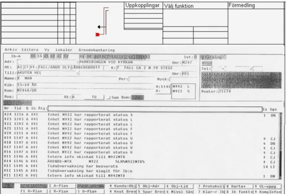
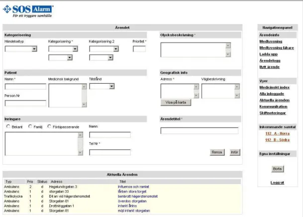
While answering a call, the operator will have a basic view in CoordCom where s/he can insert information about the case and view current cases available at the current centre. However, there are some parts in the current interface that do not seem to fulfil any function, such as the schematics next to the incoming calls in the telematic part (upper part of Figure 6). This probably remains from the time when 112 were managed by the public phone company Televerket.
Figure 6. Screenshot from the CoordCom system, the current system in use today at SOS Alarm.
Since almost 80 % of the incoming 112 calls are calls without a valid reason, the interface should consist of an easy way to disregard these calls as quickly as possi-ble, e.g. by a click of a button. SOS Alarm has an automated information service for those who are calling without a valid reason; clearly all prank and abusive calls should be redirected to the automated information service. Furthermore not all incoming 112 calls are handled by SOS, e.g. if someone calls in and reports that their car has been stolen, it would be a police matter. So redirecting calls should be a procedure that ought to be performed quickly and easily.
3.2.3 The current system in use today – CoordCom
As seen in the screenshots of the current user interface of CoordCom in Figure 6, the operators have the following input fields when answering an incoming emergency call:
• Event type.
• Injury categorisation.
• Fine injury categorisation (that is dependent on the injury categorisation).
• Priority.
• A little field with accident description.
• Patient name.
• Patient social security number.
• Address.
• Phone number.
Normark also explains that there is a lot of information that is passed on verbally between operators. She gives the example of the medical background of the patient – he blacked out because of his high blood pressure, because he forgot to take his medicine. Or the current state of the patient – e.g. unconscious. Even road descrip-tion if the locadescrip-tion is difficult to find.
The state of the caller can be crucial when determining the validity of the emer-gency. Is the caller influenced by drugs? Is s/he a friend or family member? There are some people that call SOS Alarm as frequently as twice or three times a day, some of whom just want to talk and are under no immediate danger. Many of them are known to the operators and most operators will immediately dismiss the call. However, all calls, valid and invalid ones, must be logged in case of a mistake, so it can be a good idea to include caller description in the case.
Also, today there is only room for one injury categorisation, and in cases where the patient suffers from multiple symptoms the second one is passed on verbally to the emergency unit(s), e.g. ambulance. For example if the patient suffers from a high fever and falls down a pair of steps and break his/her legs. The introduction of a sec-ond categorisation field, which does not take much room in the GUI would save the dispatch operator time and help her/him to avoid forgetting to give this information verbally to the appropriate unit(s).
In cases that are of priority 1 an operator must be able to dispatch a unit within 90 seconds of answering a call. In order to be able to dispatch a unit, the dispatcher needs three pieces of information: a priority to decide when to dispatch a unit, an address which in turn will generate an area code that the dispatcher needs in order to choose units from the correct area, and finally the dispatcher needs to know what has happened so that s/he chooses a unit with the proper equipment. The answering operator, on the other hand, needs to know if the case already exists so that a case does not get recorded more than once. So, priority, address, cause of the emergency and the case list need to be easily accessible.
3.2.4 The dispatching operator
The dispatcher’s work consists of choosing a vehicle, dispatching it, and monitoring its development. Choosing the right vehicle can be difficult as there are many con-tingencies: Is the vehicle adequately equipped? Has anyone (another organisation e.g. the hospital) planned anything for this ambulance? Will there be any free ambulances left if I pick this one?
There is a vast amount of varied kinds of information that the operator might need in order to pick an ambulance. I believe that based on the area code and the categorisa-tion of the accident, the system can filter out amongst the vehicles and present a few of them to the operator. This will save some time for the operator if the choice of units is reduced.
The mobitex system that dispatchers use to send text messages to the units can also benefit from some modification, or maybe some maturing, as it is still relatively new. The dispatcher often calls a unit telling them that s/he is going to send a mo-bitex message before sending the actual message. This is clearly inefficient, but hopefully these problems will be addressed by the company that created the mobitex system as it lies outside the scope of this thesis.
3.3 Summary of the main issues we wanted to address
Here follows a list of the most central issues that we wanted to address in this pro-ject. More about how they were being implemented can be seen in section 4.3.
• The ability to work remotely from another centre. This can be done by replacing the current local database with a distributed one; adding shift notes for local events and improving local knowledge for remote operators.
• Removing some of the components from the old layout that do not seem to fulfil any function such as the telematic schematics.
• Extending the call redirecting function to include a redirection of prank calls to the automated information service.
• More nuanced case file – improve accountability of work between operators, introduction of a second injury categorisation, information about the caller, medical background and state of the patient, and increased geographical information with the help of road description.
• Introduction of a filtering system for the emergency units based on area code and injury categorisation to facilitate the selection process for the dispatcher.
4 The Prototype Design Process
Once the analysis of the work performed by the operators at SOS Alarm was com-pleted, we began compiling a set of requirements for the prototype system. This was done by a series of meetings between Normark and I where we would go through each step carefully and ask ourselves “what goals do the operator want to accom-plish here, and how will the system help them to accomaccom-plish these goals?”. After answering these questions we wrote down the answer on a whiteboard. After a cou-ple of meetings we managed to obtain a comcou-plete set of requirements (see Appendix A).
With the help of these requirements we were able to start drawing GUIs for the whole system. We started by drawing some sketches on paper and experimented on how to group information together so that the GUI becomes as consistent and as structured as possible. These paper sketches served as a foundation for the ‘look and feel’ and interaction of the prototype (all the paper sketches can be seen in Appendix B). Once the paper sketches were completed I began translating them into actual GUIs for the corresponding programming environment.
4.1 Procedure for creating the requirements
We began by drawing a timeline on the white board with only one starting point, an incoming call, and one ending point, closing the case. Then we carefully stepped through all the possible actions that the operators perform, all events that occur and the requirements that are needed in the system during the whole course of a case. An action could be something like the operator answering the call or the operator re-questing a “listen in”. An event could be: a call coming in, a dispatch unit reporting status ready. A requirement could be: the operator being able to see all of the current cases for a specific centre or if a caller has called at most five hours before, the case that is associated with the phone number of the caller should be seen when the operator answers the call.
We wrote down each one of these actions, events and requirement6 on small pieces of post-it paper. After writing a couple of papers we started to see a work pattern. That’s when we started to divide the timeline into different phases and pasted the different pieces of papers into the corresponding phase on the white board.
6 For the remaining paragraphs in this section I will refer to the actions, events and requirements as
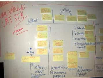
Figure 7. Overview of half of the requirements.
This method of collecting the requirements on post-it papers and pasting them on a white board in different places on the timeline proved to work-out quite well as it much facilitated the development of the prototype system. The benefits with this method were that it was very visual as you have all the pieces of information scat-tered across the timeline, i.e. you can see the big picture very easily by moving back a step or two (Figure 7) or you can also look at a specific requirement by moving in closer (Figure 8).
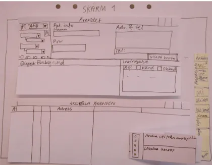
Figure 8. An example of a requirement.
This scalability and visual perception, in my opinion, is easier to work with than writing down all the requirements as long list on several pages of paper. Of course, after we completed pasting all the requirements on the white board we proceeded to writing them down as a long list. This was done also to give each requirement more detail, to explain the effects of a specific requirement on the system and the motiva-tion behind each requirement. However, during the development phase I also found looking at the photographs we took of the white board to be a real asset, especially when I wanted to get an overview of the whole system.
4.2 System Requirements
We divided the timeline into 8 different phases. However, these phases are not dis-tinct, there is no invisible barrier between them, and all of them are inter-connected and overlap with each other. It was helpful to define a case using these eight differ-ent phases in order to understand how the operators at SOS Alarm perform their work and also to understand how to build an application for this domain.
In short these eight different phases can be summarised as follows:
Phase 1. The interview is initiated by the receiving operator that answers an emergency call with “112 what has occurred?” and waiting for a response.
Phase 2. The receiving operator categorises the emergency by assessing for example if it is an ambulance case, or what priority should the case have.
Phase 3. The case is documented and labelled, by writing down all the infor-mation gathered from the caller.
Phase 4. The dispatch operator receives the case either through a receiving operator that requests a “listen in” or by choosing the case from a list of available cases.
Phase 5. The dispatch operator has a case and s/he then chooses appropriate re-sources, e.g. an ambulance with the right type of equipment.
Phase 6. After the choice is made, the dispatch operator sends it out to the cor-rect address.
Phase 7. The dispatch operator or the shift leader monitors the development of the case should there be need to intervene or to add more resources. Phase 8. And finally, the dispatch operator closes7 the case after the
emer-gency has been contained, e.g. the fire has been put out or the wounded person has been taken care of and is hospitalised.
(For the entire list of requirements see Appendix A)
4.3 Interface design
In the first phase of the interaction design we drew paper sketches for the graphical user interface of the prototype system we are building. Then these paper sketches had to be translated into GUIs in the proper programming environment. I started working in visual C++, but after one week I realised that there was not enough time to finish building the prototype within the given time if I continued working in visual C++; mostly because C++ is a relatively complex programming language to work in. Therefore I chose to work in java server pages (JSP) instead. In JSP, which is a java based programming language, it is much easier and faster to develop appli-cations. The drawback with JSP is that it is not as robust and efficient as C++. For a more detailed description about the choice of programming environment see section 5.1.
7 By closing the case I mean that the case will no longer be visible on the list of available cases and
Figure 9. Paper sketch of the base view. (Case-window and current cases list view). When translating paper sketches into GUIs I had to make some alterations in the layout. When creating GUIs in visual C++ I was able to follow the ‘blue-print’ and make the layout almost identical to the paper sketches. Mostly because visual C++ is very flexible when it comes to creating GUIs since you can practically draw the lay-out any way you wish. In HTML however, the laylay-out consists of rectangular tables, so creating a layout can be very limited. When I translated the sketches into HTML GUIs I had to rearrange the whole layout but I still kept certain groups of infor-mation together so that the interaction between the operator and the system is not compromised.
Figure 10. Case window, Visual C++.
A good example of this is the case-window. In the paper sketch (Figure 9) the fields are more tightly grouped, and the flow8 of the interface within each group is from top to bottom. This interface could be replicated when using Visual C++ (Figure
10). In HTML each field has an area around it that acts like an invisible border (pad-ding) to distance it from other objects. This takes up a lot of space, and in order to be able to have a list of current cases underneath the case-window, as much vertical space as possible should be saved in order to maximise the size of the list. Therefore I modified the HTML GUI (Figure 11) so that the flow of the interface is from left to right, thus saving vertical space. As can be seen in the implementation of the inter-faces, the grouping of information has remained intact, only the placement has been changed.
Figure 11. HTML GUI, the receiving operator’s base view of EmCoord.
4.3.1 The receiving operators case window
There are several differences between this prototype system’s (EmCoord) case win-dow (top left quadrant of Figure 11 – Ärendet) and the case winwin-dow of the current system in use today at SOS Alarm (CoordCom, Figure 6).
In EmCoord we have introduced a second categorisation field to better be able to document incidents. As explained in section 3.2.3 sometimes it is necessary to have a second categorisation of the incident, such information is passed on verbally today. The accident description field was made bigger so that more information can be inserted and is made more visible to the operator. CoordCom’s accident description field is only one small input line. If the number of characters in the accident de-scription exceeds the width of the input line, the field will scroll and the characters at the beginning of the line will no longer be visible to the operator. In this way, if
the operator wants to read the entire accident description he must use the scrolling function within the input field resulting in loss of time and efficiency.
We added a medical background field so that contingency information can be added. For example if the operator receives a call about a heart attack it can be useful to know if the patient is taking any kind of medication. This kind of information is passed on verbally today and yet is of importance for the paramedics.
A field aimed for the state of the patient was added as a drop-down menu with three alternatives: conscious, unconscious or critical. This is important to the operator, e.g. if the condition is critical the case must be given priority 1 (dispatch within 90 seconds). It is also important to the paramedics in the ambulances to know what kind of equipment they are going to use, e.g. do they need a stretcher? Do the need oxygen tubes?
We also thought that a road description field could be useful as this piece of infor-mation is first passed on verbally from the receiving operator to the dispatcher, and then from the dispatcher to the emergency unit. This method of passing information in several steps is prone to errors. By introducing a road description field the infor-mation written there can be transmitted directly to the dispatching emergency unit(s).
In the caller area (Swedish: inringare in Figure 11) we added three fields. The first one was a multiple choice combo-box field for the relations of the caller to the patient, is s/he a friend, a stranger or is s/he family. The second field was the caller description, what did s/he sound like? This is useful when determining the validity of the call. As all calls are logged (even the invalid ones such as prank calls) it can be a good idea to have the description of the caller written down if it turns out that the prank call was in fact a real emergency call, as such cases do arise at SOS Alarm. The third field was for the name of caller.
Most of the fields we added are optional, except the accident description field. We had to make them optional because in cases that are of priority 1 the operators must be able to dispatch an emergency unit within 90 seconds, and during that time inter-val the operator does not have enough time to write a full description of the incident. To be able to dispatch a unit only the categorisation-, priority-, accident description-, patient name- and address field need to be filled. However, information can always be added later after the dispatch has been made.
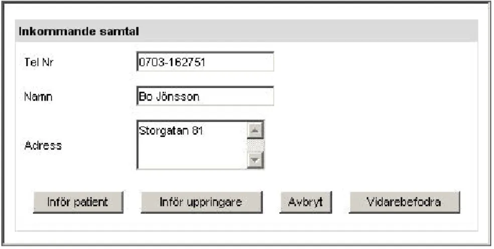
Figure 12. Incoming call window.
4.3.2 Answering a call
When the receiving operator answers a call s/he will get a pop-up window with information about the caller (see Figure 12). This window consists of three fields: the phone number of the caller, the name of the subscriber and the corresponding address. There are four ways to continue from this point.
1. The person calling is the victim, in which case the operator can use the ‘In-sert Patient’ function to transfer all three fields from the caller window to the corresponding fields in the case window with the caller name field trans-ferred to the patient name field in the case window.
2. The person calling wants to report an incident, in which case the operator can use the ‘Insert Caller’ function where all three fields are transferred from the caller window to the corresponding fields in the case window with the caller name field transferred to the caller name field in the case window.
3. The call is a silent call, in which case the operator simply cancels the call. 4. The call is a prank call or a call that is not handled by SOS, then the operator
can use the redirect function to redirect the call to the appropriate service, e.g. automated information service for prank calls, priest on duty, police, and so on.
4.3.3 The receiving operators base view
The major change in the base view is in the navigation panel (the area to the right of Figure 11). Here we have added three functions: view all operators that are logged in, view the shift notes and display the status of the operators.
The view-all-operators-that-are-logged-in feature can be useful if an operator needs help with something and wants to communicate with another operator. If that operator does not respond, the calling operator can use this feature to see what the other operator is doing. S/he could see for example that the other operator is cur-rently busy with another case, or maybe is on a break. If a dispatcher has nothing to do and sees that his colleague have been busy for a while with a big case, s/he could use this feature to see which case it is that the busy operator is working with and help her/him out.
Today the shift leader writes down important events on a white board at the begin-ning of a shift. The events written on the white board can for example be a statement that there is a marathon today, which implies that some of the larger streets in cen-tral Stockholm will be closed and traffic needs to be rerouted. However, an SOS centre can be quite large, as is the case in Stockholm and not all operators can see the white board from where there are sitting. At the beginning of a shift, the opera-tors would come up to the white board and write down the shift notes on a pad which will lay beside them for the entire shift. With a view-shift-notes feature the operator could simply log into the system and the shift notes will be presented auto-matically at start-up. This feature can later be improved so that as the shift leader adds new information to the shift notes the updates are presented automatically to every operator.
The third and final feature we added was to display the status of an operator. It basi-cally has the same function as ICQ or MSN messenger, where the status can be either of the following: online, away, working with case “Fire on Small Street”. This feature is supposed to work in conjunction with the feature that allows an operator to see what the other operators are doing.
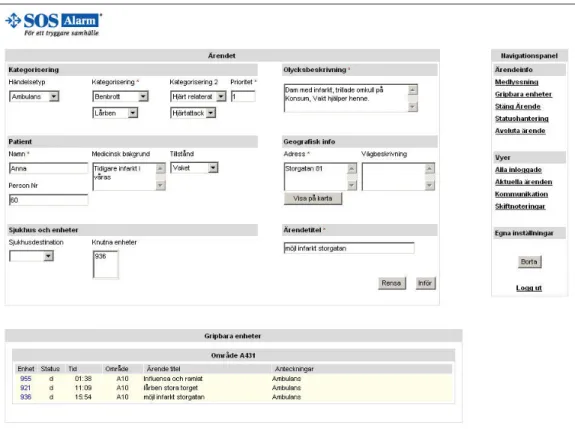
Figure 13. HTML GUI, view of the dispatch operator when assigning a unit to a case.
4.3.4 The dispatch operators view
Figure 13 is a screenshot of when the dispatch operator assigns units to a case. As can be seen, the case window is almost identical except in the lower left corner the caller information, which is irrelevant to the dispatcher, has been replaced by an area
where the dispatcher chooses which hospital should the patient be sent to and which units are assigned to that case.
In the lower part of Figure 13 the operator sees a list of available units. This list is comprised of unit number, the status of the unit – ready/unavailable/occupied, the time the specified unit was last assigned to a case, the case name if the unit is cur-rently assigned to one, and notes on the unit.
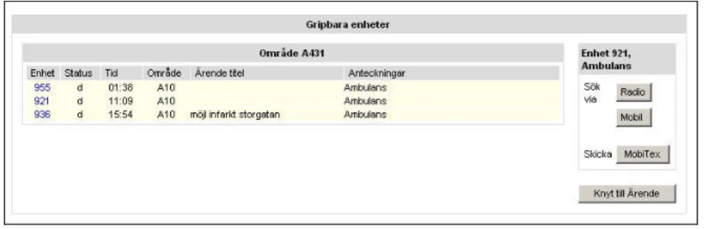
If the operator clicks on a unit that is not currently assigned to a case, i.e. the unit is available; a little box will appear at the right side (Figure 14) where the operator can choose how to communicate with that unit; by radio, mobile or mobitex. After s/he is done communicating s/he can press the assign button to assign the unit to the case the operator is currently working on.
Figure 14. Available units with the communication box to the right.
4.3.5 The shift leaders view
The shift leader’s job is to see that everything runs smoothly, i.e. all cases are handled correctly with emergency units sent within the right time interval etc. To that end the shift leader’s base view contains only a list of current cases and a navi-gation panel. By clicking on a case from the list of current cases the base view is transformed into a view with the selected case in the upper part and the case log in the lower part.
The navigation panel for the shift leader is much smaller than for the receiving operator and the dispatcher as s/he is not too concerned about the details of a case. The functions that the shift leader has in his navigation panel are more system oriented. For example, he can add new users, that is to say new operators into the system. He can also add local events and shift notes.
S/he can also use his navigation panel to view all logged in operators and what their status is, current cases at the centre and he can also use communication tools to speak with an operator.
5 The Technical Elements of the Prototype
I started by creating a relational database to store all the data associated with emer-gency cases. Then I moved on to evaluating which programming environment is best suited for building a prototype system considering stability, speed and development time. And finally, I decided which type of architecture to use when developing the actual application.
5.1 Choosing programming environment
When analysing the problem, the first thing to consider is the fact that there are sev-eral operators working with different cases at the same time and that each operator would want to access the information in the database, either by storing or by retrieving, relatively fast. For example, if someone is in dire need of an ambulance the operator should be able to dispatch an emergency unit quickly. Therefore mini-mising the time it takes for an operator to store the information in the database and dispatch the emergency unit is of utmost importance.
On certain occasions, one case can be handled by multiple operators, e.g. one operator answers the call, a second listens in and helps out with decisions and docu-mentation, and a third coordinates the ambulances. Therefore it is also of importance that this coordinative work flows smoothly and in real-time if the system is to be efficient.
Furthermore, the system should be robust and reliable. Robust since there are many operators using the system at the same time accessing the database to retrieve and store information, the database and the system as a whole should not at any point crash. And reliable because the operator that sends out emergency units wants to be absolutely sure that the units are dispatched correctly to the right address and with the right unit.
On considering all these facts it is clear that the system should be fast, able to handle coordinative real-time tasks and be robust and reliable. To achieve this, the system should be built with a language that is very close to the language of the operating system, if not the same language. In this case the choice has already been made as to which operating system to use, namely Microsoft’s windows with NT technology. To develop integrated applications for the Windows NT platform Microsoft provides developers with a development suit called visual C++ or visual C# for newer version of Windows NT, i.e. windows XP and windows server 2003.
Therefore the developing language to use for the new system should be visual C++. However, in this Master’s project I had to develop the new prototype system by my-self and the fact that this project has a time limit of 20 weeks where less than half of that time is to be spent on developing; another environment should be taken into consideration. Given that this Master’s project only involves building a conceptual prototype application to demonstrate new features and a new layout to improve performance and the interaction between operator and system, certain compromises are acceptable.
In order to successfully create a conceptual model with less than 10 weeks of devel-opment I chose to develop this application using Java Server Pages, JSP, with the open source web-server named Tomcat from Apache Jakarta, together with MySQL for the management of the database.
5.2 Designing the database
When developing the database structure I used the standard designing method for relational databases. First I started by identifying the objects and their relations. This gave me the structure9 in Figure 17:
Figure 17: Database structure of the EmCoord database.
After applying database-modelling rules and optimising the database structure by normalising to the third normal form the final structure in Table 1 and Table 2 emerged.
9 By introducing the object ‘Central’ in the structure, it enables the database to behave like it is
decentralised, i.e. you can access data from other centrals. However, for a database to be fully decentralised you have to utilise different techniques such as distributing the database over several servers. Mimicing the behaviour of a decentralised database like I have done here is only good for demonstrational purposes only. If you would fill this database with data from many different centrals, the database would quickly become very big and search times would become very slow.
Central Operator Case Street Address Area Code Zip Code Accident Caller Priority Dispatch Status Victim Injury Fine Injury Time Computer Event Type BelongsTo CaseStatus Contains HasAddress HasAreaCode HaveCaller HasInjury HasEventType LoggedIn HasZipCode HasPriority HasOpertor HasCase Asigned UnitStatus Situated LoggedInOn
Table 1. Database Objects.
Name I-term E-term
Accident AccidentNr AccidentDescr, CaseNr AreaCode AreaCode ZipCodeRange
Caller TelNr CallerName, CallerType, Comments, FirstCall-Time
Cases CaseNr CaseTitle, EventType, StartTime, StopTime, CentralNr, PrioNr, StatusNr
Central CentralNr CentralName, SystemVersion, StreetAddr
Computer ComputerNr ComputerName, Processor, OS, Memory, ComputerDescr
DispatchUnit UnitNr UnitType, RadioFreq, MobileNr, Dispatch-Time, StatusNr, CaseNr
EventType EventType
FineInjury FineInjuryNr FineInjury, FineInjuryComment, InjuryNr
Injury InjuryNr Injury, InjuryComment
Operator OpNr OpName, FullName, OpPasswd Priority PrioNr PrioDescr
Status StatusNr StatusName, StatusLetter, StatusDescr StreetAddress StreetAddr Directions, ZipCode
Victim VictimName* PNr, Age, Condition, MedicalHistory
ZipCode ZipCode Neighborhood, AreaCode
Table 2. Database relations.
Name I-term E-term
HasAddress AccidentNr, StreetAddr
HaveCaller CaseNr, TelNr CallerTime HasInjury VictimName, InjuryNr,
FineInjuryNr, AccidentNr
HasOpertor CaseNr, OperatorNr HasOperatorTime
LoggedIn CentralNr, OperatorNr LogInType, LogInTime, LogOutTime LoggedInOn OperatorNr,
5.3 Application design
To design an application with JSP technology, there are two different types of architecture available today. The first involves JSPs only, and the second uses JSPs and Servlets10 together. Referred to as Model 1 and Model 2 architectures, respec-tively, each have their own advantages and disadvantages.
The Model 1 (Figure 15) approach is the most straightforward way to use JSPs. Model 1 treats JSPs as dynamical HTML pages with embedded Java and some spe-cial tags. While this is the simplest approach, applications created with this model quickly become cumbersome as most web-servers will internally generate JSPs into Servlets and then compile this auto-generated code. If the JSPs, that contain both Java and HTML code, have syntactical errors, it can become a very tedious job to debug it, as JSPs are more difficult to debug than straight Java code.
Figure 15. Model 1 JSP architecture.
The Model 2 architecture is based roughly on the Model-View-Controller (MVC) design pattern (Figure 16). The servlet acts as the controller, taking in requests and, based on the request information, dispatching them to the appropriate JSP in order to render the response. The Model-View-Controller model is more suited to use when developing larger applications given that it separates the page layout from the busi-ness logic. A drawback of the MVC model is that it is a bit more difficult to learn.
10 A Servlet is a Java program that extends the functionality of a Web server by generating dynamic
content and by interacting with Web clients using a request-response model. For example, a client may need information from a database; a Servlet can be written that receives the request, retrieves and processes the data as needed by the client and then returns the result to the client.
Figure 16. Model 2 JSP architecture.
In short, the two major differences between the two architectures are that Model 1 is page-centric, while Model 2 is programming-centric. To develop a typical Web application that links from page to page, Model 1 may be the best approach. On the other hand, if each link or button click requires a great deal of processing and deci-sion-making about what should be displayed next, the Servlet/JSP MVC approach is the better choice. This master’s project falls into the latter group, therefore I chose to use Model 2.
6 Expert Evaluation of EmCoord
In this phase I have used the method of expert evaluation (Swedish: expert-ut-värdering) as explained in Ottersten and Berndtsson’s book. The authors define an expert evaluation as:
“An expert evaluation is an overview of an existing or suggested user inter-face. The overview is primarily based on knowledge about how the human system works and how these properties should affect the design of the user interface.”
They explain that expert evaluation is a process that can be used with little effort in order to find usability problems such as the inconsistent interface, unclear or con-fusing interaction or that the product is not designed to support the way we process information well enough. The expert evaluation resulted in a written document con-taining the result of the evaluation and recommendations on how to address these problems.
Ottersten and Berndtsson argue that the expert evaluation should be performed by an interaction designer; however s/he should not be responsible for the design of the product or prototype that is to be evaluated. This is because the designer of the product has had his/her own thoughts and line of reasoning during the design proc-ess that s/he becomes partially blind to certain aspects of the design.
The method presented in their book is divided into four stages.
• First the purpose of the product must be defined and its scope determined. In this stage the person who is evaluating the product should be given informa-tion about the target group, user situainforma-tion, tasks and the purpose of the prod-uct.
• In the second stage, the interaction designer responsible for the design of the product explains its contents and design to the person who is going to perform the expert evaluation.
• In the third stage, the “guest” interaction designer performs the evaluation.
• Finally, in the fourth stage, a report is composed containing a list of prob-lems such as design flaws, breaches in consistency, ambiguous or confusing interaction and so on. Each point could be followed up by a description of a way to attend to the problem.
In this project we invited two interaction designer experts to evaluate EmCoord. The first interaction design expert is a representative from the development team at SOS Alarm where they are designing a new system that is planning to be