Parametric Design within an Atomic Design Process (ADP)
applied to Spacecraft Design
by
Rafael Ramos Alarcon
A dissertation submitted in partial fulfillment of the requirements for the degree of
Doctor of Philosophy (Design Science) in The University of Michigan
2011
Doctoral Committee:
Professor Brian E. Gilchrist, Co-Chair Professor Colleen M. Seifert, Co-Chair Professor Richard D. Gonzalez
© Rafael Ramos Alarcon
Dedication
Acknowledgements
I have been very fortunate to have numerous individuals that have helped me throughout the research presented here. No endeavor this large can be accomplished without the involvement and support from many people.
I would like to express my profound gratitude to my advisor and co-chair, Dr. Brian Gilchrist. Your guidance and support were invaluable throughout this journey, and I feel privileged to have worked with you during this time. I look forward to future collaborations. I also thank Dr. Colleen Seifert, my other co-chair, for your feedback, encouragement and helpful advice. Thank you Dr. Peter Washabaugh, I am grateful for you giving me the opportunity to be part of your teaching world. The inspirational experiences I shared with you fueled my passion for engineering. Thank you Dr. Ixchel Faniel and Dr. Richard Gonzalez, for your assistance in the completion of this thesis.
Many members of the Space Electrodynamics and Tether Systems (SETS) group over the years have set very high working standards. You have not only provided support and companionship, but also friendship. Thank you Dave Morris, Keith Fuhrhop, Chris Deline, Louis Musinski, Iverson Bell and David Liaw.
challenges has been a privilege and source of personal joy. Hannah Goldberg, Tom Liu, Julie Bellerose, Steven Sandoval, Yang Li, Kiko Dontchev, Michael Heywood, Vikram Ivatury and everyone else, thank you for being there and your friendship. I learned a great deal from all of you.
The success of this effort was possible thanks to the funding provided by Consejo Nacional de Ciencia y Tecnología de México (CONACYT), NASA Jet Propulsion Laboratory’s Strategic University Research Partnership program and the College of Engineering Multidisciplinary Program at the University of Michigan.
My gratitude also goes to all of the EMTs, police officers and firefighters that I have worked with over the years. Working with you as a paramedic has been an honor. It has brought balance to my life and constantly renews my appreciation for it.
On a personal note, I would like to thank my family. Thank you for your faith, patience and care.
Table of Contents
Dedication ... ii
Acknowledgements ... iii
List of Figures ... vii
List of Tables ... xiii
List of Appendices ... xvii
Abstract ... xviii
Chapter 1 Motivation and Introduction ... 1
1.1 Motivation ... 1
1.2 Introduction ... 8
1.3 Summary of Research Contributions ... 9
1.4 Dissertation Overview ... 11
Chapter 2 Some Existing Design Models ... 13
2.1 Introduction ... 13
2.2 Design Concepts ... 14
2.3 Design Models ... 16
2.3.1 The Space Mission Analysis and Design model ... 16
2.3.2 Pugh’s Total Design Model (Pugh, 1991) ... 22
2.3.3 Hammond’s Multidisciplinary Design Model (Hammond W.E., 1999) .. 25
2.3.4 Hammond’s Conceptual Design Wheel and Design Process (Hammond, W. E., 2001) ... 29
2.4 Criteria for Good Design ... 34
2.4.1 Common design elements ... 35
2.4.2 Design elements that enable good design ... 43
Chapter 3 Relevant Disciplines and a Design Model ... 49
3.1 Introduction ... 49
3.2 Space Systems Engineering ... 50
3.2.1 The Space Systems environment ... 50
3.2.2 Current Space Systems design paradigm ... 54
3.2.3 Risk inherent to Space Systems ... 56
3.3 Information Science ... 56
3.3.1 User centered approach ... 58
3.4 A Design Model ... 60
3.4.1 An Atomic Design Process ... 60
3.4.2 Update to an atomic Design Process ... 64
3.5.1 ADP and the Space Mission Analysis and Design (SMAD) process
(Section 2.3.1) ... 67
3.5.2 ADP and Pugh’s design model (Section 2.3.2) ... 68
3.5.3 ADP and Hammond’s Multidisciplinary Design Model (Section 2.3.3) . 70 3.5.4 ADP and Hammond’s Conceptual Design Process (Section 2.3.4) ... 71
3.6 Systems Engineering Concepts ... 72
3.6.1 Requirements ... 73
3.6.2 System budgets ... 73
Chapter 4 Implementation of the Design Model ... 80
4.1 Introduction ... 80
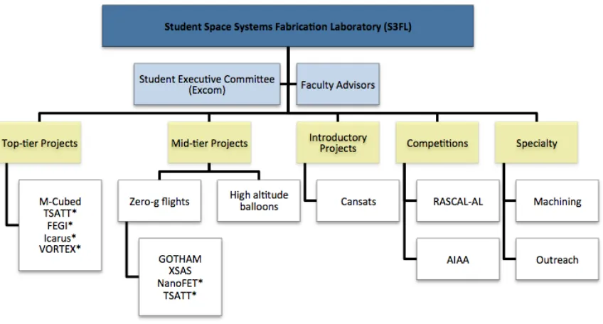
4.2 The Student Space Systems Fabrication Laboratory ... 81
4.3 Supporting Information Technology for the ADP ... 85
4.3.1 S3FL Information Management System (SIMS) ... 85
4.3.2 Other information processing tools ... 97
4.4 Human Factors ... 101
4.4.1 Culture of learning ... 101
4.4.2 Culture of leading ... 105
Chapter 5 Applying the Design Model in a Design Task ... 109
5.1 Method ... 109
5.1.1 Participants ... 111
5.1.2 The design task: Cansat ... 111
5.1.3 Procedure ... 117
5.2 Results ... 120
5.2.1 Team 1 design process ... 122
5.2.2 Team 2 design process ... 143
5.2.3 Design questionnaire analyses ... 161
5.3 Discussion ... 200
Chapter 6 Long Term Case Study: Primary Payload for Imaging Spacecraft ... 205
6.1 Introduction ... 205
6.2 ADP Experiment Design ... 206
6.2.1 The CubeSat standard ... 210
6.2.2 M-‐Cubed mission ... 212
6.3 ADP Study Results ... 217
6.3.1 M-‐Cubed primary payload design ... 218
6.4 Discussion ... 241
6.4.1 M-‐Cubed spacecraft ... 245
6.4.2 Engineering design unit ... 284
Chapter 7 Conclusions ... 288
7.1 Summary of Findings ... 289
7.2 Recommendations for Future Work ... 291
Appendices ... 294
List of Figures
Figure 1.1 The University of Michigan's first student-built satellite, Icarus, was fully
qualified for NASA's ProSEDS space tether mission (Goldberg & Fuhrhop, 2004). ... 4
Figure 1.2 The Field Emission Get-Away-Special Investigation (FEGI) project CAD model of the faceplate (top view) showing payloads including three Small Vacuum Protective Enclosures with field emitters, current collectors, miniature electrostatic analyzer, pressure sensor, photodiode and Langmuir probe (Ramos & Liu, 2005). ... 5
Figure 1.3 The Field Emission Get-Away-Special Investigation proto-flight unit NASA GAS Reservation G-187 (left) with close up of Small Vacuum Protective Enclosure (right) (Ramos & Liu, 2005). ... 7
Figure 2.1 The Space Mission Analysis and Design (SMAD) Model (Wertz & Larson, 1999). ... 17
Figure 2.2 Concept exploration flow associated with SMAD model (Wertz & Larson, 1999). ... 21
Figure 2.3 Pugh's total design model (Pugh, 1991). ... 23
Figure 2.4 Hammond's four basic components of a design process (Hammond W. E., 1999). ... 26
Figure 2.5 Hammond's Multidisciplinary Design Model (MDM) (1999). ... 27
Figure 2.6 Hammond's Conceptual Design Wheel (Hammond W. E., 2001). ... 30
Figure 2.7 Hammond's Conceptual Design Process (Hammond W. E., 2001). ... 32
Figure 3.1 A fundamental or atomic design process with process detail (Washabaugh, 1999) the numbers simply represent the sequential steps: 1. Specifications, 2. Configurations, 3. Trades and 4. Drivers. ... 61
Figure 3.2 Updated atomic design process, with iterative component between configurations and trade studies elements. ... 66
Figure 4.1 The Student Space Systems Fabrication Laboratory’s organization chart.
Asterisks denote previous projects. ... 83
Figure 4.2 Student characterizing solar panel grid (left) and students presenting at design review with industry sponsors (right). ... 84
Figure 4.3 S3FL Information Management System (SIMS) standard member general information section. ... 89
Figure 4.4 SIMS standard member current term information section. ... 90
Figure 4.5 SIMS member certifications and awards section example. ... 90
Figure 4.6 SIMS member summary of roles in S3FL example. ... 91
Figure 4.7 SIMS standard member summary of events while in S3FL. ... 91
Figure 4.8 SIMS member attendance record example. ... 92
Figure 4.9 SIMS member outreach events example. ... 92
Figure 4.10 SIMS member's comments from S3FL community example. ... 93
Figure 4.11 SIMS standard member hours and weekly reports section example. ... 94
Figure 4.12 S3FL’s information management system (SIMS) thermal vacuum module interface showing results for survivability and thermal testing for a component. ... 96
Figure 4.13 Google Docs main interface. (A) Allows documents to be managed in collections, (B) shows the user’s documents and (C) shows details of each document (Google, 2010). ... 99
Figure 4.14 Google Wave main interface. (A) Contains the user’s inbox, tools and contacts, (B) shows inbox details and participants of each wave and (C) shows a wave’s content (Google Wave, 2010). ... 100
Figure 5.1 Cansat payload shown as found post-flight, with the parachute attached (Hitsquad Team, 2009). ... 113
Figure 5.2 Cansat launch stages and separation sequence (AAS/AIAA, 2011). ... 116
Figure 5.3 Team 1 System block diagram (Cansat Team 1, 2010) – Iteration 1. ... 136
Figure 5.4 Team 1 carrier block diagram (Cansat Team 1, 2010) - Iteration 2. ... 137
Figure 5.5 Team 1 lander block diagram (Cansat Team 1, 2010) - Iteration 2. ... 138
Figure 6.12 M-Cubed primary payload and command and data handling interfacing block
diagram. ... 239
Figure 6.13 M-Cubed payload thermal test data plot to -17 °C in less than one hour to verify system survivability. ... 240
Figure 6.14 M-Cubed primary payload's image captured during vacuum test at 4.03E-05 Torr. The target observed in the image is a resolution chart at 55 cm. ... 241
Figure 6.15 M-Cubed CAD model top view showing major elements. ... 246
Figure 6.16 M-Cubed CAD model isometric expanded view. ... 247
Figure 6.17 M-Cubed System block diagram. ... 248
Figure 6.18 M-Cubed system level requirements summary. ... 249
Figure 6.19 M-Cubed Mass budget (Jan 2011). ... 250
Figure 6.20 M-Cubed Power budget (Jan 2011). ... 251
Figure 6.21 M-Cubed Cost Summary ... 253
Figure 6.22 OV2655 camera and location of lens on side panel of the spacecraft. ... 254
Figure 6.23 M-Cubed Camera mounted within the spacecraft (left side view). ... 255
Figure 6.24 OV2655 CMOS sensor point spread function with respect to pixel size. ... 259
Figure 6.25 OV2655 CMOS sensor ground resolution as a function of altitude. ... 260
Figure 6.26 OV2655 CMOS sensor cut off frequency as a function of altitude. ... 261
Figure 6.27 M-Cubed's secondary payload, JPL's Xilinx Virtex-5 FPGA that hosts the algorithm to meet MSPI's on-board processing requirements (ESTO, 2010). ... 263
Figure 6.28 JPL's COVE payload design diagram (ESTO, 2010). ... 265
Figure 6.29 CAD model with JPL’s COVE payload location in M-Cubed spacecraft. . 266
Figure 6.30 M-Cubed command and data handling block diagram. ... 268
Figure 6.31 M-Cubed main computer board Stamp9260. ... 269
Figure 6.32 M-Cubed power and electrical block diagram. ... 271
List of Tables
Table 2.1 Sub-process for characterizing the sixth step in SMAD, the mission architecture
(Wertz & Larson, 1999). ... 18
Table 2.2 Mehalik and Schunn's five tiers for good design (2006). ... 44
Table 3.1 The four main stages of the Space Mission Analysis and Design paradigm (Wertz & Larson, 1999). ... 55
Table 3.2 An example of a payload team’s partial list of requirements. ... 73
Table 3.3 Spacecraft mass budget example (showing contingency). ... 75
Table 3.4 Summary of spacecraft power electrical budget example (showing contingency). ... 76
Table 3.5 Example of a space system cost budget summary. ... 77
Table 4.1 The Student Space Systems Fabrication Laboratory Information Management System (SIMS) user categories and description of their privileges. ... 87
Table 4.2 S3FL's information management system (SIMS) operations modules and their description. ... 95
Table 5.1 Design questionnaire question example showing seven-point scale option. .. 118
Table 5.2 Participant statistics for design task using ADP, including (a) academic level and (b) field of study. ... 121
Table 5.3 Summary of information technology elements used by the teams during the design task. ... 122
Table 5.4 Team 1 mission specifications - Iteration 1. ... 123
Table 5.5 Team 1 carrier and lander specifications– Iteration 1. ... 124
Table 5.6 Team 1 communications, data and sensors specifications– Iteration 1. ... 126
Table 5.7 Team 1 configurations created for the carrier – Iterations 1 through 3. ... 128
Table 5.9 Team 1 configurations created for the deployment mechanism – Iterations 1
through 2. ... 130
Table 5.10 Team 1 configurations created for computing needs – Iteration 1. ... 132
Table 5.11 Team 1 summary of trade studies conducted for the GPS, barometric sensor, accelerometer, buzzer, voltage regulators, flash memory unit and rotary solenoid. ... 134
Table 5.12 Team 1 list of drivers identified by using the ADP model. ... 135
Table 5.13 Team 1 summary of final system design. ... 142
Table 5.14 Team 2 mission specifications – Iterations 1 through 2. ... 144
Table 5.15 Team 2 system level specifications – Iteration 1. ... 146
Table 5.16 Team 2 communications specifications – Iterations 1 through 2. ... 146
Table 5.17 Team 2 power specifications – Iterations 1 through 3. ... 147
Table 5.18 Team 2 partial list of sensors specifications – Iteration 1 through 2. ... 148
Table 5.19 Team 2 structures list of specifications - Iteration 1 through 2. ... 149
Table 5.20 Team 2 command and data handling list of specifications – Iteration 1 through 2... 150
Table 5.21 Team 2 configurations created for the system's descent – Iteration 1. ... 152
Table 5.22 Team 2 configurations created for deployment purposes – Iteration 1. ... 153
Table 5.23 Team 2 configurations considered for environmental sensing – Iteration 1. 154 Table 5.24 Team 2 summary of trade studies conducted for the structure material, structure shape, temperature sensors, pressure sensors, GPS, accelerometer and batteries. ... 155
Table 5.25 Team 2 drivers identified by using the ADP model. ... 158
Table 5.26 Team 2 summary of final system design. ... 158
Table 5.27 Mann-Whitney U test results for element "Explore problem representation". ... 167
Table 5.28 Mann-Whitney U test results for element "Using interactive, recursive and iterative design methodology". ... 169
Table 5.30 Mann-Whitney U test results for element "Use functional decomposition”. 174 Table 5.31 Mann-Whitney U test results for element "Explore graphic representation".
... 177
Table 5.32 Mann-Whitney U test results for element "Redefine constraints". ... 179
Table 5.33 Mann-Whitney U test results for element "Explore scope of constraints". .. 182
Table 5.34 Mann-Whitney U test results for element "Validate assumptions and constraints". ... 184
Table 5.35 Mann-Whitney U test results for element "Examine existing designs". ... 186
Table 5.36 Mann-Whitney U test results for element "Explore user perspective". ... 189
Table 5.37 Mann-Whitney U test results for element "Build normative model". ... 192
Table 5.38 Mann-Whitney U test results for element "Explore engineering facts". ... 194
Table 5.39 Mann-Whitney U test results for element "Explore issues of measurement". ... 196
Table 5.40 Mann-Whitney U test results for element "Conduct failure analysis". ... 198
Table 5.41 Mann-Whitney U test results for element "Encourage reflection on process". ... 200
Table 5.42 Summary of mean changes for good design elements from using ADP in the design task. ... 202
Table 6.1 M-Cubed mission nominal timeline where T is time leading to launch, and spacecraft operational time is denoted by M. ... 216
Table 6.2 M-Cubed primary payload initial major design parameters. ... 219
Table 6.3 Imaging technology comparison summary. ... 220
Table 6.4 Summary of M-Cubed primary payload main trade study (2008) ... 220
Table 6.5 M-Cubed primary payload requirements at first design iteration (2008). ... 223
Table 6.6 Summary of M-Cubed primary payload trade study (2009). ... 227
Table 6.7 M-Cubed primary payload requirements at second design iteration (2009). . 228
Table 6.8 M-Cubed payload team's risk assessment summary. ... 231
Table 6.10 M-Cubed primary payload's camera sensor trade study summary. ... 237
Table 6.11 Summary of information technology elements used by the M-Cubed payload team. ... 244
Table 6.12 M-Cubed data consumers and storage capability. ... 252
Table 6.13 Time to transmit picture calculations. ... 253
Table 6.14 OV2655 CMOS camera input parameters. ... 256
Table 6.15 OV2655 CMOS camera pixel parameters at low perigee (350 km). ... 257
Table 6.16 OV2655 CMOS camera pixel parameters at apogee (810 km). ... 257
Table 6.17 OV2655 sensor parameters at perigee (350 km). ... 258
Table 6.18 OV2655 sensor parameters at apogee (810 km). ... 258
Table 6.19 M-Cubed orbital parameters. ... 276
Table A.1 SIMS summary of system usage to date. ... 295
Table A.2 SIMS database definition of types. ... 296
Table A.3 SIMS database tables definitions for (a) announcements, (b) attendance, (c) categories of users, (d) certifications, (e) types of certifications and (f) comments. ... 297
Table A.4 SIMS database tables definitions for (a) system configuration, (b) courses, (c) events, (d) types of events, (e) history of users and (f) industry contacts. ... 298
Table A.5 SIMS database tables definitions for (a) history of industry contacts, (b) inventory, (c) history of inventory, (d) outreach, (e) types of outreach and (f) projects. 299 Table A.6 SIMS database tables definitions for (a) technical reports, (b) user status and (c) thermal vacuum test. ... 300
Table A.7 SIMS database tables definition for (a) thermal vacuum testing history and (b) system users. ... 301
List of Appendices
Appendix A SIMS Code ... 295
Abstract
Parametric Design within an Atomic Design Process (ADP)
applied to Spacecraft Design
by
Rafael Ramos Alarcon
Co-Chairs: Brian E. Gilchrist and Colleen M. Seifert
This thesis describes research investigating the development of a model for the initial design of complex systems, with application to spacecraft design. The design model is called an atomic design process (ADP) and contains four fundamental stages (specifications, configurations, trade studies and drivers) that constitute the minimum steps of an iterative process that helps designers find a feasible solution. Representative design models from the aerospace industry are reviewed and are compared with the proposed model.
Michigan), its culture (academically oriented), members that have used the design model and the description of the information technology elements meant to provide support while using the model. This support includes a custom-built information management system that consolidates relevant information that is currently being used in the organization. The information is divided in three domains: personnel development history, technical knowledge base and laboratory operations.
The focused study with teams making use of the design model to complete an engineering design exercise consists of the conceptual design of an autonomous system, including a carrier and a deployable lander that form the payload of a rocket with an altitude range of over 1000 meters. Detailed results from each of the stages of the design process while implementing the model are presented, and an increase in awareness of good design practices in the teams while using the model are explained.
Chapter 1
Motivation and Introduction
1.1 Motivation
During a historical speech at the National Aeronautics and Space Administration (NASA) Kennedy Space Center (KSC) in Florida on April 15th 2010, President Barack Obama recognized that what is needed for beyond Low Earth Orbit (LEO) exploration are revolutionizing technologies and strategic collaborative efforts, making the fundamental investments that will provide the foundation for the next half century of leadership in space exploration. He said,
"…as President, I believe that space exploration is not a luxury, it’s not an afterthought in America’s quest for a brighter future -- it is an essential part of that quest. Fifty years after the creation of NASA, our goal is no longer just a destination to reach. Our goal is the capacity for people to work and learn and operate and live safely beyond the Earth for extended periods of time, ultimately in ways that are more sustainable and even indefinite" (Obama, 2010).
Constellation Program, including the Ares I and V rockets and the Orion Crew Exploration Vehicle (Bolden, 2010a).
On February 25, 2010, Bolden addressed the Committee on Science and Technology to discuss the President's FY 2011 budget request for NASA. He stated:
"...if you gave NASA unlimited resources today, we could not take a human safely to Mars in the near future, because we have not solved the interrelated problems of shielding humans from radiation in space, providing consumables to last the distance, and constructing a rocket to take all of those items into space." (Bolden, 2010b).
This highlighted the need for developing technologies and infrastructure to enable safe human space exploration at a more sustainable rate. Discussion of partnerships between the United States and its allies to accomplish long term plans in a more cost effective manner is not optional, but essential to sending humans safely on missions beyond low Earth orbit.
A few weeks later, Congress sent a letter back to Mr. Bolden urging him to assemble a team of NASA experts to review how exploration spacecraft and launch vehicle development may be maintained with the proposed budget, ensuring that there would be uninterrupted independent United States human spaceflight access to the international space station and beyond (Congress of the United States, 2010).
force on space industry workforce and economic development plan. NASA was forthright about taking input from new initiatives to comply with the goals set within the 2011 budget. By doing this, the agency was ensuring that it received important feedback from industry, academia, and all relevant partners before it began to finalize the implementation plan for the new technology demonstrations in human spaceflight systems development activities.
Figure 1.1 The University of Michigan's first student-built satellite, Icarus, was fully qualified for NASA's ProSEDS space tether mission (Goldberg & Fuhrhop, 2004).
A follow on program, the Field Emission Get-Away-Special Investigation (FEGI) was nearing completion of its proto-flight unit by the spring of 2005. The FEGI project was on track to test experimental nano-structured electron emission devices provided from government, industry and university partners (Ramos & Liu, 2005). They were eager to see the flight results to improve next-generation propulsion technologies and spacecraft charging remediation techniques.
[image:24.612.148.493.71.378.2]the Space Shuttles. The MDA accounts for 40 lbm of the total mass, leaving 160 lbm (72.3 kg) allocated for the payload. Once the Space Shuttle reaches orbit, the NASA-provided MDA opens, exposing a 15-inch diameter experiment faceplate to the local plasma. The faceplate contains a suite of instruments including three Small Vacuum Protective Enclosures (SVPE), a pressure sensor, Langmuir probe, photodiode, current collectors and a Miniature Electrostatic Analyzer (MESA) as shown in the Computer Aided Design (CAD) model in Figure 1.2.
Figure 1.2 The Field Emission Get-Away-Special Investigation (FEGI) project CAD model of the faceplate (top view) showing payloads including three Small Vacuum Protective Enclosures with field emitters, current collectors, miniature electrostatic analyzer, pressure sensor, photodiode and Langmuir probe (Ramos & Liu, 2005).
The author had been directly involved with the project for over three years, (working first as a systems engineer and as project manager during the final two years), as were many other undergraduate, graduate students, engineers, technicians and faculty members, when NASA canceled the Getaway Special Program (GAS) completely. This left many payloads that already had a reservation to fly on the Space Shuttle without means to access space.
Figure 1.3 The Field Emission Get-Away-Special Investigation proto-flight unit NASA GAS Reservation G-187 (left) with close up of Small Vacuum Protective Enclosure (right) (Ramos & Liu, 2005).
The fact that NASA cancelled the only means to see these programs to completion enabled very negative reactions, particularly in the younger engineers to-be. It was a decision hard to understand, especially since NASA's Administrator at the time, Sean O’Keefe, had indicated that NASA was struggling with a workforce crisis with three times as many science and technology workers over 60 years of age than are under 30 years of age.
of such fundamental design algorithms and processes is at the center of the author’s professional interests.
The revolutionizing technologies and strategic collaborative efforts that President Obama was referring to will require the development of many complex systems. The knowledge domains that are involved in today’s complex systems developments (i.e. telecommunication infrastructures, modern energy systems, spacecraft development, etc.) are numerous, including engineering, engineering management, systems engineering, natural science, social sciences, and the list continues. The human capacity to predict the behavior of simple systems differs greatly from the capacity to predict that of complex systems. Wide-ranging literature can be found about systems analysis and design, and the intricate characteristics and convoluted nature of complex systems is quickly evident (Gibson, 1992; Hammond, 2001; INCOSE, 1998; Patel, 2003; Shishko, 1995; Wertz & Larson, 1999). Developing a clear understanding of existing design models and the application of a specific design model in space systems are underlying motivations for the research presented in this thesis.
1.2 Introduction
reliable information management framework that facilitates knowledge sharing and reuse across disciplinary boundaries. This is tangible due to the coupling of many sciences and personnel with various backgrounds and experiences, all coexisting in an environment with several restrictions.
Thesis:
To develop a model for initial design of complex systems, with application
to spacecraft.
The goal is to develop an initial design model for the complex systems design process, with application to small spacecraft. The model is expected to be able to capture first order constraints and their relationships by coupling the knowledge domains of space systems engineering and information science for effective information utilization and prioritization.
1.3 Summary of Research Contributions
In recognizing that the concept of design model is very broad, a specific focus has been selected for investigation. The questions that will be investigated in this thesis include – Is there a model that can help one to understand the central steps in design? What are the minimum stages in a design process to find a feasible solution? How flexible is the model studied?
There are three specific aspects of a design model that will help answer these questions: the model’s relevance, that is understanding when the model works;
adaptability, having an understanding of what kind of design problems it is good for, and
what kind of organizational culture can promote a better usage of the model; and scalability, understanding differences between applying the model to small or large problems. Research topics and contributions of this investigation include the following:
• Representative design models and their features are presented, as well as a
framework for what constitutes good design. A proposition is made for a design model for initial systems design. The model suggests it contains the central steps for design, being in essence the minimum stages for a process in finding a feasible solution.
• The usage of the design model is investigated by first explaining the context
• The long-term process of finding a feasible solution for a spacecraft imaging
system is investigated. The dominant design drivers that govern the design are indicated as they were identified; with the corresponding hardware development leading to the original spacecraft configuration that constitutes the flight unit. It is currently scheduled for launch into low Earth orbit later this year.
1.4 Dissertation Overview
This thesis is composed of seven chapters, which together address the research topic discussed in the previous section.
Chapter 1 Describes the motivation behind this research and a summary of the contributions.
Chapter 2 Explains existing design models and relevant aspects of their processes. It also includes a summary of a criterion for good design.
Chapter 3 Describes two relevant disciplines that are fundamental for the research performed (space systems engineering and information science). This chapter also includes an explanation of the design model.
Chapter 5 Describes the application of the design model in a specific design task, including details about the task, method and procedure used to characterize the impact of its usage.
Chapter 6 Explains a long-term case study, the primary payload selection for a low Earth orbit imaging spacecraft, in which all aspects of the design model were applied.
Chapter 2
Some Existing Design Models
2.1 Introduction
Many authors have developed algorithms to try to define different design processes. Most of the early design models were developed in Europe (Doordan, 1996) and some date back to ancient Egypt, Greece, Rome and other similar civilizations. Studying the modern engineering design processes became more common after the industrial revolution, when the products being developed became more complex. To work with these more complex systems, a more organized approach to their development was required, which in turn required more sophisticated algorithms and processes. A much better use of mathematics, materials selection, manufacturing processes, inventory control and robust design techniques were required to follow these algorithms and enable the processes.
sections, including the space mission analysis and design model by Wertz and Larson (1999), Pugh’s total design model (1991), and Hammond’s multidisciplinary design model (1999) and conceptual design process (2001). Finally, a summary of the work conducted by Mehalik and Schunn (2006) is explained to provide a frame of reference for what constitutes good design.
2.2 Design Concepts
There are many definitions of design, from “art with a purpose” (Getlein, 2008) to “the process of originating and developing a plan for a product, structure, system, or component with intention” (Cambridge Dictionary of American English, 2010). The following working definition will be used in this thesis. Design is the execution of a methodical process that enables the finding of a feasible solution to a particular problem (it may also prove infeasibility).
The most relevant concepts of design include:
• Goal or Objective – What a system to be designed is meant to accomplish.
• Specifications – How well the system must perform to meet its objectives. They
include the following:
• Budgets – Repositories of information critical to the design, such as system mass,
power, etc.
• Design space – The entirety of the set of possible designs.
• Decision hierarchy – The tree of choices in which each node represents a class of
related options that satisfy a goal.
• Design drivers – These are the dominant system parameters or characteristics that
directly influence the system’s performance and can be clearly identified. Some authors define drivers as those defining parameters, which most strongly affect the cost, performance and system design (Wertz & Larson, 1999). Typically system drivers are not system requirements. By explicitly identifying the design drivers, the team can concentrate the efforts on these parameters to obtain the best performance.
2.3 Design Models
Some industries are remarkably complex due to the nature of their elements and the relationships between these elements. One of these is the aerospace industry. Once in orbit, space systems typically cannot be repaired, so full functionality must be guaranteed without ever completing a single test of the vehicle in its actual operational environment. Thus, space mission success is highly associated with effective design. In 1992 a survey was published of 2,500 spacecraft failures between 1962 and the early nineties, allocating up to 24.8% of mission failures to a problem directly associated with the design of the vehicle itself (Harland & Lorenz, 2006). Therefore, it is easy to see how programs for spacecraft design are typically high cost and take a considerable amount of time. Practically all space programs schedules are measured in years.
Four design models from the aerospace industry that are representative of typical industry processes are described in the following sections.
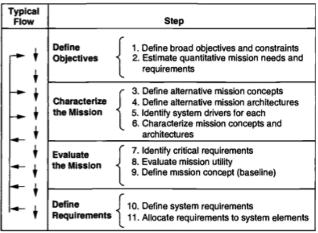
2.3.1 The Space Mission Analysis and Design model
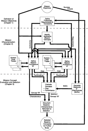
Figure 2.1 The Space Mission Analysis and Design (SMAD) Model (Wertz & Larson, 1999).
preferably conceptually distinct approaches to the problem. The practicality of available technology at a given time can be very restricting for the generation of different concepts. The next step involves the generation of a mission architecture. This is defined as the mission concept from the previous step plus a definition of elements including launch element, mission operations facilities and personnel, orbits definition, a communications architecture and a spacecraft. Step five is identifying system drivers. It is expected that there is an identification of the principal cost and performance drivers for each mission concept. The benefit of identifying these is that there will be an improvement of the chances of getting the best possible design within the available budget. Step six is described by the authors as the most involved in mission design because it defines in detail what the system is and does. The level of detail should be such that the outcomes of this stage allow meaningful evaluations of effectiveness. Although there is very complex algorithm that describes this step in depth, a summary of the series of sub-steps expected to guide this effort is shown in Table 2.1.
Table 2.1 Sub-process for characterizing the sixth step in SMAD, the mission architecture (Wertz & Larson, 1999).
Step Description
A Define the preliminary mission concept B Define the subject characteristics
E Select the mission operations approach
F Design the spacecraft to meet payload, orbit and communications requirements
G Select a launch and orbit transfer system
H Determine logistics, deployment, replenishment, and spacecraft disposal strategies
I Provide costing support for the concept-definition activity
The activities in step seven are identifying critical requirements. These requirements are those that dominate the space mission’s overall design and affect performance and cost. This leads to performing a mission utility analysis that quantifies how well the requirements and objectives are being met in step eight. Having evaluated alternative designs and performed the required trade studies and assessments on mission utility, a baseline system design is selected in step nine. The decomposition of every subsystem aspect into progressively lower levels of design by defining lower level functions, will help formally consolidate the top level requirements. The formal definition of these system requirements happens in the tenth step. Internal to the system, the documentation of interfaces between segments is key to integrating and maintaining clarity between these segments. These documents also help in allocating numerical requirements to the components of the entire space mission, a task that is fulfilled in the eleventh and final step.
It should be noted, that there is significant recognition that with the compilation of contributions over years by many engineers and managers throughout the space systems community, sometimes there are disagreements among experts regarding certain topics. The authors state, “…[SMAD] reflects the insight gained from engineers and managers practical experience, and suggests how things might be done better in the future. From time to time the views of authors and editors conflict, as must necessarily occur given the broad diversity of experience.” (Wertz & Larson, 1999).
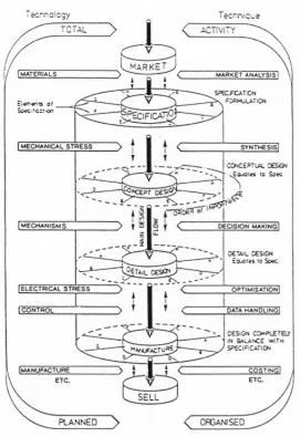
2.3.2 Pugh’s Total Design Model (Pugh, 1991)
Figure 2.3 Pugh's total design model (Pugh, 1991).
through a process of synthesis and decision-making. Pugh describes the main design flow as that between the concept design and the detailed design phases.
As the system matures within the concept design, so will the relationships within the team, the knowledge about the system and ideally the awareness of the functionality limitations of the system in order to achieve the detailed design expected from the next stage. The detailed design outcome should meet the original specifications, and only until this is the case can the designer proceed to optimization and data handling techniques. It is interesting to note that the model suggests that the design can be out of balance with specifications up until the stage in which it can actually be built, which is the
manufacturing stage. At this point, costing techniques to determine its best selling value
come into play.
A technological dimension is also part of this model. In between the market and specifications, the materials that will be part of the system are to be defined. It seems there is an attempt to create a balance between materials that are available to a particular designer and the activities of market analysis such that the available technology is maximized to deliver information from marketing into specifications.
Once the first batch of specifications is complete, the designer can transition into
the concept design phase by implementing mechanical stress analysis techniques.
Similarly, between concept design and detail design, the designer should recognize the “mechanisms” that function properly to facilitate a better transition between stages. This is an element of heritage which can help iterate faster between conceptual design and
Electrical stress and control properties of the system are required before moving into the manufacturing processes. Although the model depicts that there can be more specific activities related to the techniques that will enable the maturity of the design throughout the process, (including other technological considerations such as materials selection), this vertical iterative design process allows limited access to the original specifications from other stages.
2.3.3 Hammond’s Multidisciplinary Design Model (Hammond W.E., 1999)
Figure 2.4 Hammond's four basic components of a design process (Hammond W. E., 1999).
Figure 2.5 Hammond's Multidisciplinary Design Model (MDM) (1999).
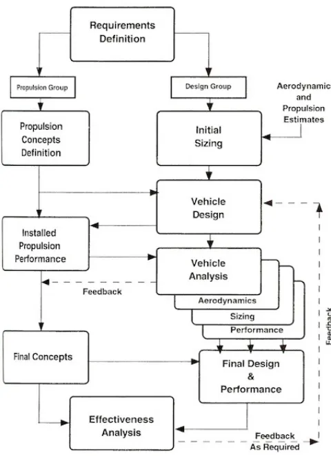
In describing the process, Hammond explains that the decision making action is at the core of the design process. Many different types of decisions must be made and decision makers, expert systems, engineers and other required expertise should be involved throughout the design process at all times. The design consists of a sequence of steps, starting from a group of ideas (initially problem definition related) that turn into concepts that, after fully understanding through testing prototypes, will shed light on design uncertainties.
The model is intended to emphasize design requirements throughout the process since it helps to control lifecycle costs. Hammond describes these lifecycle costs as largely determined early on by the design concepts and therefore very difficult to change past this stage. The vehicle design stage provides input into the propulsion performance effort that is needed for the overall system. Only through multiple trades having to do with the aerodynamics, sizing of different subsystems and components, and further study of the performance will there be a successful vehicle analysis stage completion. It is left to the discretion of the systems engineers and technical leaders that the results of these analyses are complete enough to enable feedback into the final concepts stage and a final
design and performance completion.
As a designer works throughout this process there are different points in which the configuration is frozen. Some design characteristics or specific hardware design elements begin to dominate, for example the system structure. Following the different iterative paths over time will allow the team’s knowledge of the design concept to mature. However, as more time is spent within the design process, the more likely that the design freedom will be reduced.
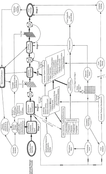
2.3.4 Hammond’s Conceptual Design Wheel and Design Process (Hammond, W. E.,
2001)
infusion from different disciplines in the middle circle to drive the core conceptual design process of the inner circle. The requirements and objectives delimit the entire process, including elements such as design criteria, selection criteria, aerospace roles, mission
profiles, payload definition (that Hammond couples with weapons integration) and
specific requirements.
Figure 2.6 Hammond's Conceptual Design Wheel (Hammond W. E., 2001).
The design synthesis stages (shown in more detail in Figure 2.7) include
configuration synthesis, identification of candidate configuration types, design
throughout iterations. All the analysis is backed up by rigorous studies in aerodynamics, structures, etc. Ultimately an “evaluation” takes into account performance, cost and effectiveness.
For a given problem there is an initial analysis that, through the documentation of mission objectives goals and requirements, will generate specific design objectives. Elements like mission profiles, pointing performance, airfield performance, payload integration components, etc. are all part of these specific design objectives. There is a design emphasis input on four levels: performance, effectiveness, cost and versatility. By going through this stage there should be a clear identification of different configuration types, which is why this stage is called Identification: candidate configuration types. This is considered Stage 1.
Stage 2 is the design development. This is the stage with the highest number of inputs due to the different dimensions that affect its constitution. The main path to follow during this stage is one of “system tuning” through explicit activities of tuning and development. Using analysis methods, scaling laws and performance detailing, there is a series of initial selections that will outline trade-offs with different sensitivities on different subsystems. These subsystems are the aerodynamic element, propulsion, specialized payload, and overall systems aspect. By understanding thoroughly what is the technology available to the organization and using cost analysis, the model suggests it is possible to identify the candidate technology that, through testing, will determine the output of the cycle. This is the link to the next stage, Stage 3.
cost estimation) that through testing constitute the design cycle for the stage. The process includes what it calls a “design satisfaction filter” from Stage 2 and Stage 3, which enables the designer to select particular technology sets that, through refinements, constitute the concept refinement stage, also known as Stage 4. A “fine filter” that comes directly from the selection criteria and evaluation metrics from a concepts element precedes the design cycle to the final stage, the final concept, which is Stage 5. Final trade-offs and sensitivities analyses feed into Stage 5 that come directly from all preceding stages in which selected concepts have been studied and specific concepts have been refined. Cost methods that have been applied from earlier stages (like stage 2 and 3) are detailed into this last design phase. All stages of this model have a relationship with an “Operations Analysis” aspect of this process, which helps verify that all the requirements and constraints are being met throughout the process.
2.4 Criteria for Good Design
With numerous design models in existence, it is crucial to be able to establish a frame of reference for what actually constitutes good design. This context will be used extensively in the following chapters when we are trying to understand the relevance and scalability of the original model researched here.
empirical studies of the design process. They began the process by identifying and clustering design process elements and stages from their past experiences in cognitive studies of design and systems engineering design. The findings and earlier frameworks of Simon (1996) and Gibson (1992) constitute the disciplinary origins of Mehalik and Schunn’s research. The authors conducted the review and coding of the journal articles. After completing this, an additional expert in engineering design reviewed a sample of 11 articles from the set of 40 to validate the coding. This expert reviewed one sample article (not included in the original group of articles) as practice after which he was given feedback through discussion with the authors. This process was repeated until the additional reviewer completed a review of ten randomly selected articles from the original group and the degree of correspondence of coding was shown to exceed 80% across all coding dimensions. The dimensions consisted of level of expertise in design, level of expertise in domain, type of task examined, etc. Mehalik and Schunn show in detail, which elements of the design process have been studied most frequently and, of those that have been studied, which have actually contributed to an effective design outcome. The following paragraphs describe these common design elements.
2.4.1 Common design elements
2.4.1.1 Explore problem representation
Exploring the problem representation should begin by examining the goal defined and having the team work together to understand what needs to be accomplished. What are the qualitative goals, and why? The way in which the design space is perceived will have an impact on different aspects of the design, chosen solution paths, and the goals and constraints by which designers are bound.
2.4.1.2 Explore graphical representation or visualization
This element involves using visual means to construct a representation. Sketches that designers may use, or graphics software such as CAD programs, fall under this element. This does not include verbal representations, such as lists of specifications, or quantitative representations, such as list of different measurements. Ultimately, visual representations also help a team communicate better, since they can agree on spatial relationships based on the graphical representations.
2.4.1.3 Use functional decomposition
designed and sometimes tested as components separately, and then reassembled into an overall design.
2.4.1.4 Explore engineering facts
Aspects that can be investigated by the designer from a specific knowledge domain can help support the decision of a feature of the design. It is good practice for designers to explore engineering facts whenever possible to make sure that the underlying assumptions, especially early on in the design, are correct.
If there is a laboratory- or company-wide knowledge database, pursuing activities related to exploring engineering facts can help to discover heritage in the design process that either the team or another design team has worked on previously.
2.4.1.5 Explore issues of measurement
mission objectives are called measures of effectiveness or figures of merit. Measures of effectiveness (MoEs) generally fall into one of three broad categories associated with discrete events, coverage of a continuous activity or timeliness of the information of other indicator of quality (Wertz & Larson, 1999). Metrics are robust for analysis, test and evaluations but defining them sometimes can be challenging.
2.4.1.6 Build normative model
An ideal system constitutes a normative representation or model of the design. By relaxing the limitations and constraints, the designers are able to represent a feasible solution much quicker. There are certain steps to respond to a developing normative model. Here, the designers systematically identify top-level system performance parameters and associated requirements and proceed to decompose them into a set of lower-level quantifiable and assessable elements. This needs to be done carefully, because relaxing constraints can cause unintended introduction of variability and uncertainty that can lead to poor decision making.
2.4.1.7 Explore scope of constraints
that limit how this system can fulfill those goals. Constraints may be conceptual, physical, economical or practical.
2.4.1.8 Redefine constraints
There can be multiple interpretations when it comes to redefining constraints. The authors describe this element as an activity in which the designer decides to investigate further what is involved with the constraint or set of constraints to reconfigure the way that the constraint primarily affects the design. Instead of focusing on a specific constraint to examine the extent it governs the design, the designer may temporarily redefine the constraint in order to achieve an original goal, temporarily using a design that may not otherwise conform to the original constraint.
2.4.1.9 Conduct failure analysis
2.4.1.10Validate assumptions and constraints
Validation of assumptions and constraints can be done through a number of ways. In inexperienced teams during early design phases, periodical reviews with experts in the different fields provide the perfect opportunity to check that some of the initial assumptions are legitimate. Another way to validate constraints is through the development of simple prototypes. Sometimes these prototypes are specifically built to gain knowledge on one or two constraints that some of the more experienced engineers identify early on. Particularly in the educational setting, sometimes engineering students may not get the opportunity to have the experience of developing prototypes to validate assumptions as a part of a design process, and they miss out on the opportunity to understand the importance of this activity.
2.4.1.11Search the space (evaluate design alternatives)
The element of searching the space is likely to be the most creative of all the design elements. There are no limitations on how far a particular designer may wish to explore to ensure that different design alternatives have been considered. The best designers develop their own approach for complex system design. They may use various strategies and specific procedures that have worked for them to guide them systematically through the design process.
infrastructure that allows the designer to guide this effort can eventually be used when a particular concept that turned out to be more complicated than originally anticipated is no longer feasible, allowing the team to quickly focus on an alternative and resume the design process.
2.4.1.12Examine existing designs
The authors state that this element describes a subset of activities of the search the space criterion (Section 2.4.1.11). In many industries, the ability to state that a particular design has heritage (meaning certain subsystems or features have been built in the past and performed successfully) immediately boosts the team’s confidence in their approach. This is because a particular component or even an entire subsystem has already gone through the rigorous process of understanding its points of failure, limitations, strengths and overall design maturity.
2.4.1.13Follow interactive, recursive and iterative design methodology
The introduction of new requirements from a customer, changes in the environment, and budget alterations are examples of some of the realities that sometimes force designers to have to iterate through their design methodology a greater number of times than they originally anticipated.
2.4.1.14Explore user perspectives
To begin the design of any system, the designers must address the system’s purpose and the questions that need answering. The design model they follow will help them go through a process in which they will adequately describe the system, so that ultimately they can build it and finally test it, ideally in its operating environment. However, many designers concentrate only on acquiring information from the user at the beginning of the process, resulting in errors due to the omission of important points. Some engineers believe that constant interaction and validation from the user will improve results.
2.4.1.15Encourage reflection on design process
Reflection on the design process can be an individual or a team experience. Groups that habitually practice self-reflection in the process of solving problems will help increase the team’s level of expertise over time. This is not only relevant when there is a failure, but also when the system has met its original specifications.
2.4.2 Design elements that enable good design
The ultimate goal of Mehalik and Schunn was to have a strong context by which it might be determined what enables good design, particularly through the elements used in the design process (explained in Section 2.4.1).
Table 2.2 Mehalik and Schunn's five tiers for good design (2006).
2.4.2.1 Tier I: Design elements significant for good design (High reporting frequency)
The design elements that are reported with a high degree of frequency among the best designs in the study conducted by Mehalik and Schunn (2006) are:
• Explore problem presentation
The authors conclude that people who used at least one of these three strategies in their design process showed the most positive design outcomes. Incidentally, it is recognized that the three design elements are associated with expert design practices that are effective.
2.4.2.2 Tier II: Design elements may be significant for good design (High reporting
frequency)
Only one element is categorized as significant for good design in this tier:
• Use functional decomposition
The authors state that although this element was mentioned throughout the articles they studied, it was not always mentioned in association with the design. One reason they insinuate could be that functional decomposition is a necessary aspect of design, but the strategy is not perceived to make a large difference in achieving what is ultimately thought to be good design.
2.4.2.3 Tier III: design elements significant for good design (Moderate reporting
frequency)
• Explore graphic representation
• Redefine constraints
• Explore scope of constraints
• Examine existing designs • Explore user perspective
The authors explain that confidence in this categorization can likely be increased if the database they use for their study included a larger number of articles.
2.4.2.4 Tier IV: design elements may be significant for good design (Moderate
reporting frequency)
One of the elements that was mentioned overall less frequently as associated with good design is:
• Build normative model
2.4.2.5 Tier V: items requiring further study (Low reporting frequency)
The authors describe that the low reporting frequency categories which are associated the least with good design are good candidates for further study. These categories are:
• Explore engineering facts
• Explore issues of measurement • Conduct failure analysis
• Encourage reflection on process
Although the authors explain that the reporting of these items may be due to the types of journals considered in their analysis, they observed that there tended to be less emphasis on engineering content and facts in the empirical studies themselves. More specific engineering content and particularly measurements, techniques, knowledge and tools used tend to be reported in engineering journals for specific disciplines, rather than as a focus in the design process study. They also note, that few studies focus on the importance of design failures for improving design outcomes, and also represent possible areas for additional study for how the design processes can be better. The authors explain that from an educational standpoint, teaching of design ought to focus on the first tiers that have been documented to have higher levels of impact for achieving effective design.
Chapter 3
Relevant Disciplines and a Design Model
3.1 Introduction
Design models are intended to capture a system’s components and their relationships. As seen in Chapter 2, different models have varied approaches to enable the designer to perform his job, for example from a functional perspective, an operational perspective or modifying an existing design.
3.2 Space Systems Engineering
Space systems are composed of all the applied technology, organizations and personnel forming the entirety of the space industry network, including: spacecraft, ground stations, data links among spacecraft, mission or user terminals, launch systems and all related supporting infrastructure.
Typically spacecraft are designed for a variety of missions, including communications, Earth observation, meteorology, navigation, planetary exploration or warfare. While there is heritage in the design, there are often unique features to each mission that require innovation from engineers, scientists and technicians as they go through some part or variation of a design process to ensure that the mission is a success.
3.2.1 The Space Systems environment
3.2.1.1 Pre-‐launch environment
Since the design and fabrication of spacecraft is a process that usually takes years, components and subsystems of the spacecraft may be stored for extended periods of time prior to launch. It is important that there is adequate environmental control during such periods to avoid potentially harmful degradations. This is particularly an important consideration if the assembly of the launch vehicle takes place in locations like Kennedy Space Center in Florida, where there is a higher concentration of oxidants because of its proximity to the ocean.
3.2.1.2 Launch
The placement of any spacecraft into its intended operational environment is considered the launch. It imposes a highly stressful environment on the spacecraft during its ascent, where the vehicle is subjected to significant axial loads by the acceleration of the launch vehicle, as well as lateral loads from steering and wind gusts. There are significant vibration and acoustic energy inputs throughout the entire system for the duration of the transport.
Spacecraft are mounted rigidly to the launch vehicles; therefore, they need to be designed to withstand the vibration and expected loads for the corresponding launch vehicle that they will be mounted on.
3.2.1.3 Vacuum
conduction to all elements of the vehicle. Different materials will outgas to some extent in a vacuum environment, and metals will usually have a thin film in their outer layer composed of gases that have been absorbed during the fabrication period of the vehicle.
3.2.1.4 Solar radiation
Solar radiation is naturally occurring and dominates particularly at what are considered high altitudes (above 800 km). It is comprised of impingement of solar photons upon the spacecraft surfaces. The pressure exerted on the vehicle is dependent on these types of surfaces, which can be transparent, absorbent or reflective. The solar radiation pressure p(N/m2) on a given surface of the satellite (in the vicinity of the Earth) exposed to the sun can be determined as (NASA SP 8027, 1969):
!=4.5 × 10!!cos![ 1−!
! cos!+0.67!!] ( 3.1 )
where θ is the angle (degrees) between the incident radiation vector and the normal to the surface, and ks and kd are the specular and diffuse coefficients of reflectivity. The worst
case solar radiation torque is (Wertz & Larson, 1999):
!!" = ! !!"−!" , ! =!!
! !!(1+!)cos!
( 3.2 )
where Fs is the solar constant, 1,367 W/m2, c is the speed of light 3x10⁸ m/s, As is the
surface area, !!" is the location of the center of solar pressure, cg is the center of gravity,