doi:10.4236/epe.2013.54B073 Published Online July 2013 (http://www.scirp.org/journal/epe)
LVRT Research of PMSG Wind Turbine Using
Feedback Linearization
Jie Wei1, Zhenyu Lin2, Nian Liu1
1Smart Grid Key Laboratory of Sichuan Province, School of Electrical Engineering and Information,
Sichuan University,Chengdu, China
2College of Electrical and Electronic Engineering, Huazhong University of Science and Technology, Wuhan, China
Email: [email protected]
Received February, 2013
ABSTRACT
Analyzing the wind turbine with a direct-driven PMSG, this paper proposes a low voltage ride through scheme of PMSG wind power systems based on feedback linearization. The DC-Link voltage is controlled by the generator-side converter rather than the grid-side converter. Considering the nonlinear relationship between the DC-Link voltage and the generator rotor speed, the controller of DC-Link voltage uses a feedback linearization technology. The grid-side converter which controls the grid active power according to the maximum power point tracking adds a judgment link for the generator speed reference. The model of 2 MW PMSG wind power system was simulated by using PSCAD. The simulation result has verified the validity of the proposed control scheme.
Keywords: PMSG; DC-Link Voltage; Converter; PSCAD
1. Introduction
Among various renewable energy sources, the applica-tion of wind power generaapplica-tion in the world has been rap-idly growing. Unlike the DFIG (double fed induction generator) wind power system, direct-drive PMSG (per-manent magnet synchronous) wind power system have some advantages such as simple structure, high power generation efficiency, high precision and high operating reliability[1].
Because of the growing proportion of the wind field, the grid-connected conditions of wind power generator are more and more important. In recent years, many countries in the world have promulgated special inter-connection rules and processes for large-scale wind power units through a grid code [2,3].
Scholars at home and abroad have proposed a large number of schemes for the LVRT (low voltage ride through) capability of the DFIG wind turbines [4-7],but researches on direct-drive PMSG is very limited. Refer-ence [8] increased the speed of the generator and reduced the converter input power in order to realize the LVRT, but the improving level is very limited and the DC-Link voltage may exceed the limit. In [9] and [10], Crowbar circuit absorbed the unbalanced power in the power grid fault, however, in this way, the unbalanced power would be completely waste, which needing the support of load
and heat dissipation. The STATCOM can be used to supply the reactive power compensation for wind power turbines in the power grid fault [11], however, when the fault occurs and ends, the cut-in and cut-out of the STATCOM make the control more complex, and in-vestment cost is also great.
For PMSG wind power system with back-to-back PWM converters, in the conventional control method [12], the generator rotor speed is controlled by the gen-erator- side converter, and the grid-side converter control the DC-Link voltage. Considering the nonlinear rela-tionship between the DC-Link voltage and the generator rotor speed, this paper proposes an improved control method of the power conversion. The DC-Link voltage is maintained within regular range by the generator-side converter which introduces feedback linearization control technology. The generator speed reference ω* is output by the grid-side converter for the maximum power point tracking, and the ultimate value ωw* is got after com-parative judgment with ω*.
2. Mathematical Model of PMSG
Wind Power Sysrem
According to the aerodynamics,the simplified mathe-matical model of wind turbine is formulated as[13]:
2 3 1
( , ) 2
/
w p
w
P R v C
R v
(1)
*The project sponsored by Science and Technology Department of
where Pw is the extracted wind power, ρthe air density, v the wind speed, R the rotor radius, ωw the wind turbine speed, Cpthe efficiency coefficient.
In the synchronous d-q coordinates, the mathematical model of PMSG are[14]:
sd
sd s sd d q sq sq
sq s sq q d sd
di
u R i L L i
dt di
u R i L L i
dt (2)
where usd and usq are the d-q stator voltage, isq and isq the d-q stator currents, Rs and Ls are stator resistance and inductance, ωthe generator speed, magnet flux.
Using the control strategy of , the generator electromagnetic torque is:
0 d i 3 2 e n
T p i sq (3)
where n is the number of pole pairs.
Neglecting the loss of converter and generator, the generator power and the DC-Link capacitor C are:
p
w
g w w
d
P P J
dt
(4)
dc
c dc g gri
du
P u C P P
dt
d (5)
where Pgis the generator power, udcthe DC-Link voltage, Pgrid the gird power.
Combining Equations (4) and (5), a dynamic equation can be introduced:
5 3
3
1 1
2
dc w
dc p w w grid
du d
u C R C J P
dt dt
(6)
In the above Equation (6), the nonlinear relationship between udcand ωw can be shown.
3. Control Strategy
3.1. Control Scheme of the Grid-side PWM Converter
When the wind turbine power P is less than the rated power, the rotor speed reference ωw* can be expressed as follows by P[15]:
* 0.67 2 1.42 0.51
w P P
(7) According to Equation (7) for the MPPT, the rotor speed reference ωw* can be got.
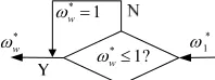
As shown in Figure 1, when the rotor speed is greater than 1p.u, ωw* is set to 1 in order to make the generation system can according to the active power demand of the gird-side ensure that the generator rotor work in the best reference.
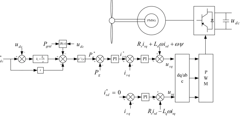
The control block diagram of the grid-side PWM con-verter is shown in Figure 2.
[image:2.595.372.471.86.123.2]* w * 1? w * 1 * 1 w
Figure 1.Control block diagram of the grid-side PWM con-verter. * 1 1?
Figure 2.Control block diagram of the grid-side PWM con-verter.
3.2. Control Scheme of the Generator-side PWM Converter
The state equations of a single input and single output system can be represented as follows:
( ) ( ) ( )
x f x g x u y h x
(8)
Where x is the state vector, u the control input, y the output, h the smooth scalar function, f and g are the n
dimensional smooth vector field.
The nonlinear Equations (4) (5) can be written in the state equations as follows:
1 1
1 1
grid
dc dc dc
g
w w
w w
P
u u C u C
P P J J (9)
For the system design methodology, the DC-Link vol-tage is used as the control input. In order to realize the linear process, the output y is for the difference.
( ) f ( ) g ( )
y h f g u L h x L h x
u
(10)
where is the first order Lie derivatives of h(x) along f, along g. Here, the first order Lie de-rivatives is defined as follows:
( ) f L h x
( g L h x)
f
g
h
L h hf f
x g
L h hg f
[image:2.595.313.531.167.311.2]379
Without loss of generality,Equation (12) is given as: paper simulates 2 MW PMSG wind power system based on PSCAD. Imitating the grid connection point voltage drops to 50% in 1 s -1.5 s, the proposed new method is compared with the conventional method in this paper. The system parameters are as follow.
( ) ( )
( ) ( )
g
f
L h x A x
L h x B x
(12)
Hence, Equation (13) can be derived from Equations
(10) and (12). PMSG: Stator rated voltage 690 V, Magnetic induc-tion 1p.u, Stator phase resistance 0.008 p.u, Direct- axis inductance Xd 0.062 p.u,Quadrature axis in-ductance Xq 1.1477 p.u.
( ) ( )
y B x A x u
(13) Combining Equations (9) and (13), Equation (14) is
represented as follows: Wind Turbine: Air density 1.225 kg/m
3, Rated wind speed 10m/s.
1 ( )
1 ( )
grid dc
dc
A x P
u C
B x u C
(14)
Converter: DC-Link voltage 1100V, Rated output voltage 690 V, Reactive power setting value 0 Mvar, Grid frequency 50 Hz.
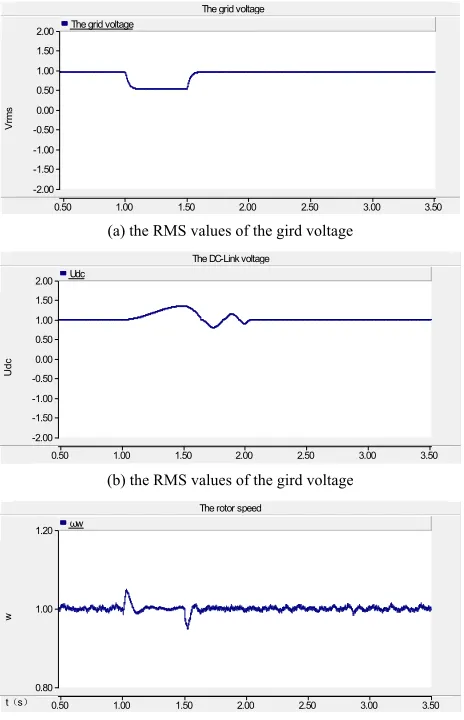
The grid output power is minished along with the grid connection point voltage drops to 50%, which, at the same time, causing the generator output power reduction. The unbalanced power between the grid-side and the generator-side will cause DC-Link voltage rise to 1.3 p.u. The performance of DC-Link voltage udc for the conven-tional method is as shown in Figure 4(b). However, in the new method, udc is almost constant, as shown in Fig-ure 5(b). Because of the unbalanced power, a portion of energy has stored in the wind turbine, thus, the rotor speed ωw would enhance. But the rising is less than 0.08 p.u which is within the safe range, as shown in Fig-ure 4(c) and Figure 5(c). With the failure to eliminate, it turns back to the normal value.
Feedback law can generally be written as:
1
( ) ( )
u B x
A x
v
(15)where v is the equivalent input.
In order to eliminate and reduce the steady-state error of the system, Equation (16) can be deduced from the PI control.
1 2
ref ref ref
vy k y y k
y y dt (16)where yrefis the reference value, k1and k2 are the adjust-able gains.
5. Conclusions
The control block diagram of the nonlinear DC-Linkvoltage and the generator-side PWM converter is shown
in Figure 3. This paper proposes a low voltage ride through scheme of PMSG wind power systems based on feedback lin-earization. The DC-Link voltage is maintained and regu-lated by generator-side converter. The control scheme of the generator-side converter has been designed using
4. Simulation and Analysis
To verify the validity of the proposed algorithm, this
*
dc
u
dc
u
s
2 1
k k
s
( )
B x
1( )
A x
grid
P udc
*
g P
g
P
* s q
i
s q
i
s sq d sd
R i L i
sq
u
* 0
sd
i
s q
i
sq
u
s sd q sq
R i L i
[image:3.595.102.503.523.718.2]dc
u
The grid voltage
0.50 1.00 1.50 2.00 2.50 3.00 3.50 -2.00
-1.50 -1.00 -0.50 0.00 0.50 1.00 1.50 2.00
Vr
m
s
The grid voltage
(a) the RMS values of the gird voltage
The DC-Link voltage
0.50 1.00 1.50 2.00 2.50 3.00 3.50 -2.00
-1.50 -1.00 -0.50 0.00 0.50 1.00 1.50 2.00
Ud
c
Udc
(b) the RMS values of the gird voltage
The rotor speed
t(s) 0.50 1.00 1.50 2.00 2.50 3.00 3.50 0.80
1.00 1.20
w
ωw
[image:4.595.307.540.84.207.2](c) the rotor speed ωw
Figure 4. Simulation of the conventional method for power system fault.
The gird voltage
0.50 1.00 1.50 2.00 2.50 3.00 3.50 -2.00
-1.50 -1.00 -0.50 0.00 0.50 1.00 1.50 2.00
V
(
p.u
.)
The gird voltage
(a) the RMS values of the gird voltage
The DC-Link voltage
0.50 1.00 1.50 2.00 2.50 3.00 3.50 -2.00
-1.50 -1.00 -0.50 0.00 0.50 1.00 1.50 2.00
Ud
c
Udc
(b) the RMS values of the gird voltage
The rotor speed
0.50 1.00 1.50 2.00 2.50 3.00 3.50 0.80
1.00 1.20
w
ωw
(c) The rotor speed ωw
Figure 5. Simulation of the new method for power system fault.
feedback linearization, and the grid-side converter regu-lates the power for MPPT. The simulation result demon-strates the validity of the method. When the grid voltage sags to 50%, the proposed algorithm can effectively de-crease the rising of DC-Link voltage, and keep it almost invariable so that the LVRT capability of PMSG wind power systems is improved. Wind turbines can still run in parallel operation until return to normal operating condition during power system fault.
REFERENCES
[1] H. Polinder, F. F. A van der Pijl and P. Tavner,
“Com-parison of Direct-drive and Geared Generator Concepts
for Wind Turbines,” IEEE Transactions on Energy
Con-version, Vol. 21, No. 2, 2006, pp. 725-733.
doi:10.1109/TEC.2006.875476
[2] C. Saniter and J. Janning, “Test Bench for Grid Code
Simulations for Multi-MW Wind Turbines, Design and
Control,” IEEE Transactions on Power Electronics, Vol.
23, No. 4, 2008, pp. 1707-1715.
doi:10.1109/TPEL.2008.925425
[3] GB/T2008-327 “State Power Grid Corporation of
Tech-nical Requirements for Wind Farms”.
[4] H. M. Li, X. Y. Zhang, Y. Wang and X. R. Zhu, “Virtual
Inertia Control of DFIG-based Wind Turbines Based on
the Optimal Power Tracking,” Proceedings of the CSEE,
Vol. 32, No. 7, 2012, pp. 32-39.
[5] L. Liang, J. L. Li and H. H. Xu, “ Reactive Power Control
Strategy for Doubly-Fed Induction Wind Power
Genera-tion System Under Fault in Power Network,” Power
Sys-tem Technology, Vol. 32,No. 11, 2008, pp. 70-73,
[6] J. H. Zhang, J. Wang and X. Y. Chen, “Analysis of
DFIG-based Wind Generation LVRT Control Strategy,”
Power System Protection and Control, Vol. 39, No. 21, 2011, pp. 28-33.
[7] G. Q. Li, Y. N. Qian and M. X. Liu, “Research on Low
Voltage Ride through Control Strategies for Doubly Fed Induction Generator Based on Sliding Mode Control,”
Power System Protection and Control, Vol. 40, No. 1,2012, pp. 5-11.
[image:4.595.57.289.85.445.2]381
Dip ride-through Control of Direct-drive Wind Turbines,”
Proceedings of t he 39th International Universities Power Engineering Conference, Bristol, UK, 6-8 September, 2004, pp. 934-938.
[9] C. Abbey and G. Joos, “Effect of Low Voltage Ride
through (LVRT) Characteristic on Voltage Stability,”
Proceedings of IEEE Power Engineering Society General Meeting, San Francisco, CA, USA, Vol. 2, 2005, pp. 1901-1907.
[10] W. Li, C. Abbey and G. Joos, “Control and Performance
of Wind Turbine Generators Based on Permanent Magnet
Synchronous Machines Feeding a Diode Rectifier,”
Pro-ceedings of the 37th IEEE Power Electronics Specialists Conference, Jeju, Korea, 2006, pp.1-6.
[11] B. Singh, R.. Saha, A. Chandra and K. Al-Haddad, “Static
Synchronous Compensators (STATCOM): A Review,”
IET Power Electronics, Vol. 2, No. 4, 2009, pp. 297-324.
doi:10.1049/iet-pel.2008.0034
[12] N. W. Miller, J. J. Sanchez-Gasca and W. W. Price,
“Dy-namic Modeling of GE 1.5 and 3.6 MW Wind Turbine
Generators for Stability Simulations,” IEEE Power
Engi-neering Society General Meeting, Vol. 3, 2003, pp.1977- 1983.
[13] J. Yao, Y. Liao and K. Zhuang, “Coordinated Control
Strategy of Back-to-back PWM Converter for Permanent
Magnet Direct-driven Wind Turbine,” Automation of
Electric Power Systems, Vol. 32, No. 20, 2008, pp.88-107.
[14] M. Yin, G. Y. Li, J. C. Zhang, et al., “Modeling and
Con-trol Strategies of Directly Driven Wind Turbine with
Permanent Magnet Synchronous Generator,” Power
Sys-tem Technology, Vol. 31, No. 15, 2007, pp. 61-65. [15] J. G. Slootweg, S. W. H. de Haan and H. Polinder,
“General Model for Representing Variable Speed Wind turbines in Power System Dynamics Simula-tions,” IEEE Transactions on Power System, Vol. 18, No. 1, 2003, pp. 144-151.