Research Article
a
April
2018
Special Issue: National Conference on Emerging Trends in Engineering 2018
Conference Held at Sri Venkatesa Perumal College of Engineering & Technology, Puttur, A.P., India
Computer Science and Software Engineering
ISSN: 2277-128X (Volume-8, Issue-4)
A Neuro Controller based SVPWM for Stand – Alone PV
System
S. Vasantharaj1, P.Dhanasekaran2
Assistant Professor1,2, Dept. of Electrical & Electronics Engineering,
Arunai Engineering College, Thiruvannamalai1, Sri Venkatesa Perumal College of Engineering and Technology2
E-Mail: [email protected], [email protected]
Abstract: In this paper, the Space Vector Pulse Width Modulation (SVPWM) control strategies is used for the implementation of Impedance Source Inverter (ZSI) based Solar Energy Conversion system was explained. The solar irradiation and temperature are mainly depends on the output power produced from the PV conversion process. The proposed method is capable of tracking MPPs rapidly and accurately without steady-state oscillation, thus, its dynamic performance is more efficient. In this proposed method the SVPWM is used to treat the sinusoidal voltage as a constant amplitude vector rotating at constant frequency. This project proposes a MPPT method, based on Neural Network Controller (NNC) with a ZSI applied to a stand-alone photovoltaic system. By adjusting the shoot-through duty cycles of the Z-Source network the maximum power from the solar PV system is transferred to the stand alone system. Hence the harmonic distortion in the output voltage or current will be less. The inverter output current for driving a load should be noted such that it does not carry the harmonic content. However since disturbed sine wave is unavoidable under various factors it is necessary to reduce the harmonic level to obtain a highly effective output. The results are generated in MATLAB/ SIMULINK and are shown.
Keywords: Photovoltaic (PV), Impedance Source Inverter (ZSI), Maximum Power Point Tracking (MPPT), Maximum Power Point (MPP), Space Vector Pulse Width Modulation (SVPWM), Direct Current (DC), Alternating Current (AC), Total Harmonic Distortion (THD).
I. INTRODUCTION
Comparing to all renewable energy sources, solar power systems attract more attention because they provide excellent opportunity to generate electricity while greenhouse emissions are reduced. The only way of generating electricity from solar energy will be PV cells or panels. Temperature, insolation, spectral characteristics of sunlight, dirt, shadow, etc., are the main factors to be considered for the efficiency of solar cells. The PV cells are made up of silicon, which is also used in computer "chips". The radiation produced from the sun will be converted into direct current (DC) by this Photovoltaic process. This point is known as maximum power point (MPP). There will be a non – linear variation in the locus of this point with solar irradiation and the cell temperature. The MPPT [1],
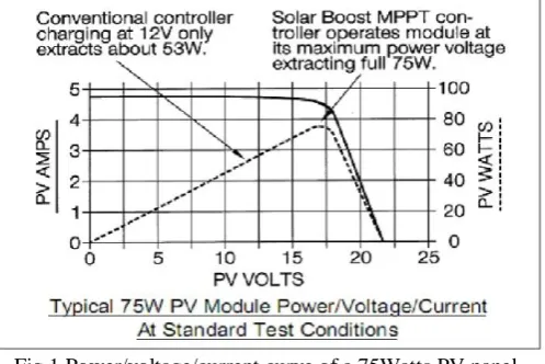
[2] is the efficient way to track the maximum available output power of the PV system. The PV panel module physically moves to point directly at the sun and which the MPPT is not a mechanical tracking system. The graph (Fig 1) shows the PV module Power/Voltage/Current and the traditional Current vs. Voltage curve for a standard test conditions of 25°C cell temperature and 1000W/m2 of insolation.
Fig 1.Power/voltage/current curve of a 75Watts PV panel.
ISSN(E): 2277-128X, ISBN: 978-93-87396-07-4, pp. 382-390
II. CIRCUIT DIAGRAM DESCRIPTION
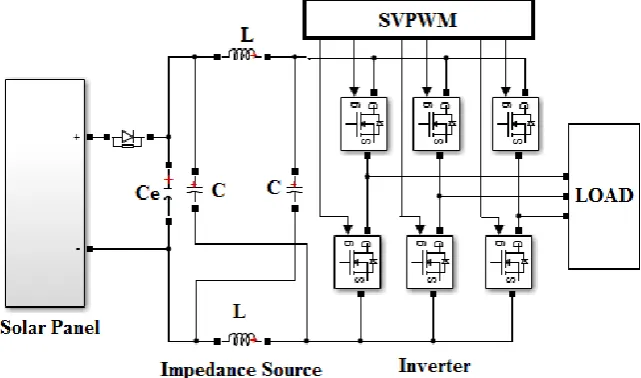
In this solar PV system the power is generated by the solar irradiation and insolation temperature. The maximum available power will be extracted by the operation of PV generator at its MPP, by the role of MPPT. The figure 6 shows the general block diagram for a solar PV system with MPPT, using a Impedance Source Inverter (ZSI). The main objective of this MPPT [8] technique is to obtain the maximum power from the PV generator. The inductor which is used as a filter which reduces the current ripple content in the DC output current and the filter capacitor reduces the ripple content in the DC link voltage providing a relatively stiff voltage source for the PWM inverter. The ZSI [6] is used to get constant voltage and constant frequency. The buck/boost operation can be achieved using a three level ZSI, to maintain the constant voltage in the load sideby selecting the proper value of the Modulation Index. The proper value of shunt capacitor of the inverter can reduces the voltage ripple content in the DC link voltage. To control output voltage of the impedance source inverter, the SVPWM strategies are the effective, especially describing a lower total harmonic distortion (THD). The power factor is mainly depending upon the generated voltage and the wind velocity conditions. The shunt capacitor is used to filter the DC link voltage ripples in the rectifier output.The output voltage and frequency is controlled by the pulse width modulation technique.
Fig 2.CircuitDiagram of proposed method.
III. MODELING OF PHOTOVOLTAIC ARRAY SYSTEM
The equivalent circuit of the PV cell is shown in fig 3.
Fig 3.Equivalent Circuit of a PV Cell
The basic equation of I – V characteristic of the ideal PV is mathematically described from the theory of semiconductors (1)
Where,
(2)
Therefore,
(3)
Where,
Ipv,cell is the current generated by the incident light (it is directly proportional to the Sun irradiation),
Id is the Shockley diode equation,
I0,cell is the reverse saturation or leakage current of the diode, q is the electron charge (1.60217646 × 10⁻¹⁹ C),
ISSN(E): 2277-128X, ISBN: 978-93-87396-07-4, pp. 382-390
Fig 4.Origin of I -V equation of an Ideal PV cell
The fig 4 shows the origination of the I – V curve for the equation (2). Practical arrays are made up of multiple modules. The observation of the characteristics at the terminals of the PV array requires the inclusion of additional parameters to the basic equation.
(4) Where,
V = NskT/q is the thermal voltage of the array with Ns cells connected in series.
RS& RP is the equivalent series and parallel resistance of the array. The cells connected in parallel which increases the
current and the greater output voltage will be produced by the cells connected in series. The array is composed by Np
parallel connections of cell, the PV and saturation currents may be expressed as,
𝐼𝑝𝑣 = 𝐼𝑝𝑣 ,𝑐𝑒𝑙𝑙∗ 𝑁𝑝 (5)
𝐼𝑜= 𝐼𝑜,𝑐𝑒𝑙𝑙 ∗ 𝑁𝑝 (6)
This equations originate the I-V curve in figure 4 below, where the three outstanding points are highlighted: short circuit (0,Isc), Maximum Power Point (Vmp, Imp), and open circuit (Voc, 0).
Fig 5.Characteristic I-V curve of a practical PV module
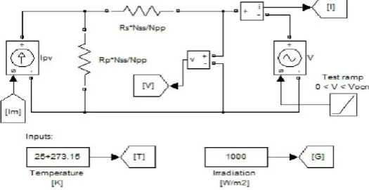
The PV panel is modeled [9], [10] as an equivalent current source. From the MATLAB Simulink library the mathematical model for the various equations describing the PV panel characteristics are modeled. The below figure 5 shows the equivalent circuit model of the PV panel. This simulation is done for standard test condition (STC) when temperature is 25 C and Irradiation is 1000 W/m2.
Figure 5. Equivalent circuit of solar PV using MATLAB
ISSN(E): 2277-128X, ISBN: 978-93-87396-07-4, pp. 382-390
Fig 7. Reverse saturation current (Io) using MATLAB
Fig 8. Current generated by the incident light (Ipv) of PVusing MATLAB
IV. SPACE VECTOR PULSE WIDTH MODULATION (SVPWM) TECHNIQUE
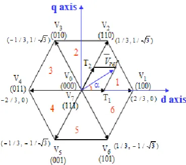
Space vector modulation (SVM) is an algorithm for the control of pulse width modulation (PWM). It is used for the creation of alternating current (AC) waveform. It is most commonly used in inverters, 3 phase ac powered motors. A three phase voltage vector is transformed into a vector in the stationary d-q coordinate frame which represents the spatial vector sum of the three phase voltage.It is used in the reduction of total harmonic distortion (THD) created by the rapid switching. With the increase of levels, traditional approaches of SVM based on five-level or seven level inverters are hardly realized. The vectors (V1 to V6) divide the plane into six sectors (each sector: 60 degrees). This section explains
about this SVM scheme. Any three-phase system (defined by ax(t), ay(t) az(t)) can be represented uniquely by a rotating
vector as,
𝑎𝑠=23 𝑎𝑥 𝑡 + 𝑎. 𝑎𝛾 𝑡 + 𝑎2. 𝑎𝑍(𝑡) (7)
Given a three-phase system, the vector representation is achieved by the following 3/2 transformation:
𝐴𝛼
𝐴𝛽 =
2 3.
1 −1
2 −1
2
0 3
2 − 3
2
.
𝑎𝑋
𝑎𝑌
𝑎𝑍
Where (Aα, Aβ) are forming an orthogonal 2-phase system and aS = Aα + jAβ. A vector can be uniquely defined in the
complex plane by these components. The reverse transformation (2/3 Transformation) is given by,
𝑎𝑋 𝑡 = 𝑅𝑒 𝑎𝑆 + 𝑎0(𝑡)
𝑎𝑌 𝑡 = 𝑅𝑒 𝑎2. 𝑎𝑠 + 𝑎0(𝑡)
𝑎𝑍 𝑡 = 𝑅𝑒 𝑎. 𝑎𝑠 + 𝑎0(𝑡)
𝑎0=
1
3. 𝑎𝑋 𝑡 + 𝑎𝑌 𝑡 + 𝑎𝑍(𝑡)
Fig 9.Space vector d,q-axis locations and their switching vectors and sectors
ISSN(E): 2277-128X, ISBN: 978-93-87396-07-4, pp. 382-390
V. NEURAL NETWORK CONTROLLER
An ANN is a mathematical model that tries to simulate the structure and functionalities of biological Neural Networks. Basic Building Block of every ANN is artificial neuron, which is simple mathematical model (function). Such a model as three simple of sets of rules: multiplication, summation and activation. At the entrance of artificial neuron the inputs are weighted what means that every input value is multiplied with individual weight. In the middle section of artificial neuron is sum function that sums all weighted inputs and bias. At the exit of artificial neuron the sum of previously weighted inputs and bias is passing through activation function that is called transfer function (fig 10).
Fig 10. Working Principle of an Artificial Neuron
The body of an artificial neuron that sums the weighted inputs bias and “processes” the sum with transfer function. At the end an artificial neuron passes the processed information via output(s). Benefit of artificial neuron model simplicity can be seen in its mathematical description below:
𝑦 𝑘 = 𝐹 𝑤𝑖 𝑘 . 𝑥𝑖 𝑘 + 𝑏
𝑚
𝑖=0
(8)
Where,
xi(k) is input value in discrete time k where i goes from 0 to m,
wi(k) is weight value in discrete time kwhere igoes from 0to m,
b is bias,
F is a transfer function,
Yi(k) is output value in discrete time k.
VI. SIMULATION, HARDWARE AND SYSTEM RESULTS
The input to the Impedance Source Inverter is the voltage and power signals from the PV panels which are analog signals. The output from the ZSI is given to the motor load. The Space vector PWM which is used in the circuit reduces the harmonic content from the inverter circuit and hence the inverter performance will be efficient. The implementation of the MPPT controller, initially modelling and simulation of the controller employing ZSI using the MATLAB/Simulink was carried out. Figure 11 shows the developed PV model system consisting of PV array, Impedance source circuit with an MPPT controller connected to an inverter and a load. The simulation is used for validating the developed hardware prototype.These input capacitors serve as the DC source feeding the Z-source network and are used to suppress voltage surge that may occur due to the line inductance during diode commutation and shoot-through mode of the inverter, thus requiring a small value of capacitance.
ISSN(E): 2277-128X, ISBN: 978-93-87396-07-4, pp. 382-390
Fig 12.Simulink Results of the PV Pa Fig 13. Simulink Results of Impedance Source Voltage Fig 13. Simulink Results of Impedance Source Voltage
Fig 14. Waveform for speed and Torque.Fig 15. Three Phase Motor Current
The harmonic level is high which does not suit the standard limit. By using the ANN controller the voltage and current harmonics of the same system is reduced. It is observed that the voltage and the current harmonics are 11.97% and 1.90% respectively which is shown in the figure 16 and 17 respectively.
ISSN(E): 2277-128X, ISBN: 978-93-87396-07-4, pp. 382-390
Fig 18. Proposed prototype model
The input 1Φ / 50Hz / 230V is switched ON keeping the auto transformer at the initial condition. The auto transformer is adjusted by increasing the input to 7.5V. The figure 19 shows the output measured using DSO for the line voltage and the input pulses generated for the ZSI. The input pulse for the ASI which is operated at a frequency of 1.136 kHz. The peak-peak voltage is 15.4V for period of 20ms. The RMS value is 5.45V.
Fig.19: Input Voltage& Input Pulse for ZSI
The solar power is then fed to the impedance source which produces the controlled DC voltage source to feed the inverter circuit. The output voltage from the Impedance Source is shown in the figure 20. The output obtained is 6.90V.
Fig. 20: Impedance Source Output Voltage& Output Load Voltage
ISSN(E): 2277-128X, ISBN: 978-93-87396-07-4, pp. 382-390
VII. CONCLUSION
The proposed work demonstrated the state of art DC-AC power converter technology. The mathematical analysis of Impedance source Inverter is developed. A novel method for the tracking of MPP was investigated in order to improve the efficiency of PV systems, under different temperature and irradiance conditions. The design and simulation of a ZSI based MPPT controller was proposed using MATLAB. The proposed method has very good performances, fast responses with no overshoot and less fluctuation in the steady state, for rapid irradiance and temperature variations. By using the Neural Network controller the PV System efficiency will be increased. These controllers are able to maintain very rapidly and the operating point of the PV systems at the maximum power point hence improving the amount of energy effectively extracted from the PV modules.
REFERENCES
[1] Pahlevaninezhad. M, Das. P, Drobnik, Jain P.K, Bakshai. A, “A ZVSInterleaved Boost AC/DC Converter Used in Plug-in Electric Vehicles”, IEEE Transactions on Power Electronics, vol. 27, no. 8, 2012, pp. 3513-3529.
[2] Mousavi A, Das. P, Moschopoulos. G, A Comparative, “Study of a New ZCS DC–DC Full-Bridge Boost Converter With a ZVS Active-Clamp Converter”, IEEE Transactions on Power Electronics, vol. 27, no. 3, 2012, pp. 1347 – 1358.
[3] Sung Sae Lee, Gun Woo Moon, “High-Efficiency Boost Half-Bridge Converter With Fast Boost Current Transferring ZVS Operation”, IEEE Transactions on Power Electronics, vol. 23, no. 4, 2008, pp. 1822-1829.
[4] Seung-Wu Rhee, Gun Woo lee, “Coupled Inductor Incorporated Boost Half-Bridge Converter With Wide ZVS Operation Range”, IEEE Transactions on Industrial Electronics, vol. 56, no. 7, 2009, pp. 2505-2512.
[5] Ch. Hua and Ch. Shen, “Comparative study of peak power tracking techniques for solar storage system”, IEEE Transactions on Applied Power Electronics Conference and Exposition (APEC’98), Vol. 2, 1998, pp. 679-685.
[6] Azadeh Safari and SaadMekhilef, “Simulation and Hardware Implementation of Incremental Conductance MPPT with Direct Control Method Using Cuk Converter”, IEEE Transactions on Industrial Electronics, vol. 58, no. 4, 2011, pp. 1154-1161.
[7] Ahmed K. Abdelsalam, Ahmed M. Massoud, Shehab Ahmed and Prasad N. Enjeti, “High-Performance Adaptive Perturb and Observe MPPT Technique for Photovoltaic- Based Micro grids”, IEEE Transactions on Power Electronics, vol. 26, no. 4, 2011, pp. 1010-1021.
[8] Jian-Long Kuo, Kai-Lun Chao, and Li-Shiang Lee, “Dual Mechatronic MPPT Controllers with PN and OPSO Control Algorithms for Rotatable Solar Panel in PHEV System”, IEEE Transactions on Industrial Electronics, vol. 57, no. 2, 2010, pp. 678-689.
[9] MummadiVeerachary, TomonobuSenjyu, and Katsumi Uezato, “Neural – Network Based Maximum Power Point Tracking of Coupled Inductor Interleaved Boost Converter Supplied PV System Using Fuzzy Controller” IEEE Transactions on Industrial Electronics, vol. 50, no. 4, 2003, pp. 749-758.
[10] Nobuyoshi Mutoh, Masahiro Ohno, and Takayoshi Inoue, “A Method for MPPT Control While searching for Parameters Corresponding to Weather Conditions for PV Generation Systems”, IEEE Transactions on Industrial Electronics, vol. 53, no. 4, 2006.
[11] Nicola Femia, Giovanni Petrone, Giovanni Spagnuoloand Massimo Vitelli, “Optimization of Perturb and Observe Maximum Power Point Tracking Method”, IEEE Transactions on Power Electronics, vol. 20, no. 4, 2005, pp. 963-973.
[12] Oscar López-Lapeña, Maria Teresa PenellaandManelGasulla, “A New MPPT Method for Low-Power Solar Energy Harvesting”, IEEE Transactions on Industrial Electronics, vol. 57, no. 9, 2010, pp. 3129-3138
[13] Villalva M G “Modelling and circuit-based simulation of photovoltaic arrays”, IEEE Transactions on Power Electronics, vol. 25, no. 5, 2009, pp. 1198 - 1208.
[14] Yao-Ching Hsieh, Te-Chin Hsueh and Hau-Chen Yen “An Interleaved Boost Converter with Zero-Voltage Transition” IEEE Transactions on Power Electronics, vol. 24, no. 4, 2009, pp. 973 - 978.
[15] Ehsan Adib and Hosein Farzanehfard, “Zero Voltage Transition PWM Converters with Synchronous Rectifier”, IEEE Transactions on Power Electronics, vol. 25, no. 1, 2010, pp. 105 – 110.
[16] N. Lakshminarasamma, Md. Masihuzzaman, and V. Ramanarayanan, “Steady State Stability of Current-Mode Active Clamp ZVS DC-DC Converters”, IEEE Transactions on Power Electronics, vol. 26, no. 5, 2011, pp. 1295 – 1304.
ISSN(E): 2277-128X, ISBN: 978-93-87396-07-4, pp. 382-390
BIOGRAPHY
Mr. S. Vasantharaj has received the Bachelor degree in Electrical and Electronics Engineering from
M. Kumarasamy College of Engineering, Anna University, India in 2008 and the M.E degree in Power Electronics and Drives from Jeppiaar Engineering College, Anna University, India in 2013. Currently he is working as an Assistant Professor in Arunai Engineering College, Tiruvannamalai. He has worked one year for Gulfmax International LLC, Dubai and one year for LMD Electricals and Engineering works, India in Electrical Maintenance. His area of interest includes in the field of Solar PV Systems, Power Converters.