Research Journal
Volume 10, No. 32, Dec. 2016, pages 150–155
DOI: 10.12913/22998624/65120 Research Article
A MATHEMATICAL MODEL OF CHP2000 TYPE PROGRESSIVE GEAR
Paweł Lonkwic1
1 The State School of Higher Education, Mechanical Engineering Faculty, Pocztowa Str. 54, 22-100 Chełm, Poland, e-mail: [email protected]
ABSTRACT
The project of CHP2000 type progressive gear has been presented in the article. The offered solution from its construction point of view differs from the existing solutions due to the application of Belleville springs packets supporting the braking roller cam and achieving a flexible range of the gear loading. The standard concept of the gear loading within a mathematical and a geometrical model has been presented in the ar-ticle. The proposed solution can be used in the friction lifts with the loading capacity from 8500 up to 20 000 N.
Keywords: safety gears, geometrical design, CAD, mathematical model.
INTRODUCTION
A great number of publications regarding the friction lifts pay attention to the various forms of surveillance over the machine operation. The way to describe a cargo lift accelerations is pre-sented in the publication by Filas and Mudro [2012] with the use of the reduction method of the lift operation supervising system. The prob-lem connected with various polyurethane mate-rials used as the lift driving element is touched in Gardyński, Lonkwic publication [2014]. More-over, the authors analyze what kind of impact the different types of polymers have on the guide roller deformation during the lifting device
stop-page.The problem of stresses and the hydraulic
lift frame deformation while sharp braking with the use of instantaneous gears was presented in the publication [2011] by Kayaoglu, Salman and Candas A. Developed results have a significant impact on safety coefficients of the lift frame construction. In Lonkwic [2014] publication the author presents a new type of progressive gears the construction of which is based on the cam-mechanism. The cam-mechanism operation de-pends on complicated pile of Belleville springs
with the stresses value dependent on the lifting device nominal loading capacity. In a different publication by Lonkwic, Szydło [2014], the au-thors’ concept of an innovative device to strain the speed limiter rope, the operation of which de-pends on the force value applied by the tension-ing sprtension-ing with the use of which the proper value of friction force between the line and the speed limiter wheel is achieved, has been presented. The authors: Taplak, Erkaya,Yildirim, Uzmay in their publication [2014] made the use of a mathematical method applied in neural nets to predict the lift vibrations. In this particular case the methodology to measure and predict vibra-tions constitutes an important aspect of research studies over the device proper operation as well as undesirable consequences of vibrations in the device construction. The research studies over efficiency of the braking hydraulic system used in hydraulic lifts are described in the publica-tion [2013] by Xu, Cheng, Yang, Zhang, Yang. The aspects of comfort and delay on the basis of five selected types of gears are described in the publication [2015] by Lonkwic. The influence of the gears construction on the braking distance length is analyzed by the author.
While analyzing professional literature on re-search and development within mechanical side of the lifting devices incomprehensive approach to the mathematical description of braking sys-tems in friction lifts can be observed. Therefore, further research studies should be executed with-in the applicable subject area.
A GEOMETRICAL MODEL OF CHP2000
GEAR
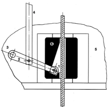
Instantaneous gears presented in Figure 1 are characterized by progressive braking characteris-tic what as a consequence is reflected in a very high coefficient of delay sometimes equaling to 2 g. With such a high delay coefficient, the passen-gers travelling in the cabin as a result of a rapid braking process were exposed to vast injuries what due to more restricted safety regulations became unacceptable. Progressive gears, presented in Fig-ure 2 by definition, are the gears the construction of which enables gentle braking of speeding cabin in such a way that the obtained delay is in a range from 0.2 to 1 g. Sudden braking of the friction lifts can be caused by the following factors:
• the broken off carrying tension rods,
• the power plant failure, leading to the sudden cabin speed acceleration.
Under a regular operation none of the above listed cases has appeared, that is why within re-search studies prior to the lifting device is released to operation, a series of tests is performed on the basis of the records included in 81.1 standard.
The proposed solution presented in Figure 2 consists of the body 1, in the middle of which there is a cam 5 leaning on the two packets of Belleville springs 4. Along the cam the braking roller 2 moves, the change of its position is de-fined via a lever which is not presented in Figure 2. At the maximum deflection of a braking roller
Fig. 1. Diagram of instantaneous safety gears
Fig. 2. Diagram of progressive safety gears of CHP2000 type
in the opposite side, there are the braking plates 3, the task of which is to increase the friction coefficient between the guide – the roller – the plate. A geometrical model describing depen-dencies between the gear main subassys has been presented in Figures 3, 4 and 5.
In order to define the maximum loading of the gear the equations of the mechanical system
balance were used. Thus, the balance equations for the gear body are described by the following formulas (1), (2), (3):
(1)
(2)
(3)
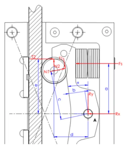
The geometry of forces affecting the gear cam while braking and directly after the cabin stop is presented in Figure 2. The balance equations for the presented mechanism are expressed with the following equations (4), (5), (6):
(4)
(5)
(6)
The forces impacting the gear roller at the maximum location while braking are presented in Figure 5. The above is presented by the equation (7):
(7)
The equations of frictions between the gear construction subassys are described by the fol-lowing equations:
(8)
(9)
(10)
(11)
The value of pressure put by the packet of Belleville springs on the cam while braking can be determined with the use of the above men-tioned mathematical description. Taking into ac-count the above and assuming that the braking force is a superposition of all friction forces de-pendent on Belleville springs operation located in the gear mechanism, the braking force is shaped in the following way:
(12)
Fig. 4. A geometrical model of the forces existing in the gear cam
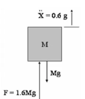
The gears loading of the friction lift is pre-sented in a diagram in Figure 6. On the basis of the above Figure and the equations the weight of the gears loading mass is described by the for-mula (13).
(13)
THE GEAR GEOMETRY VERSUS BRAKING
DISTANCE
The chart presented in Figure 7 illustrates differences in a braking roller free movement for various types of the gears. The a.m. differ-ences are observed from the central position to the roller contact position with the guide sur-face. Differences in the free movement values are the consequence of differences in the gears construction. The distance covered by the cabin during the whole braking cycle in the real sys-tem is a superposition of the lever movement caused by a changed position of the speed lim-iter wheel, the free movement of the gear roller as well as an effective braking distance during which the reduction of the moving cabin speed takes place.
Fig. 7. Chart presents the value of the gear roller idling distance depending on the
gear construction
Fig. 6. The lift model: force – acceleration - gravity
During the braking process there is a depen-dence between the total amount of friction forces and the gear loading equation, which can be ex-pressed in the following way:
(14) Where:
f – The friction superficial coefficient. Fs – Braking force.
k – Distance between the packet of Belleville springs center and the geometrical centre of the gear body.
l – Distance between the revolution centre of the cam and the geometrical centre of the gear body.
m – Distance between the plate centre and the geometrical centre of the gear body.
n – Distance between the plate edge and the geo-metrical centre of the gear body.
Nn – The normal forces elements. Tn – The friction forces elements. P – The lift system total mass. R – The gear roller external radius. Rn – The reaction elements.
Q – Nominal loading capacity.
α – The gear cam angle. µ – Friction coefficient.
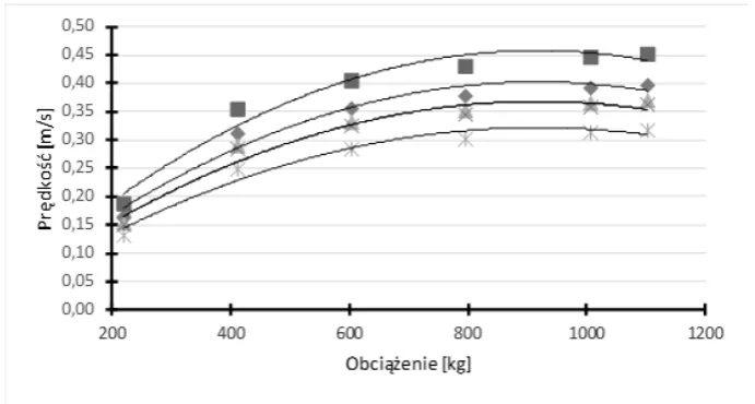
Taking into consideration the gear roller movement a theoretical effective braking distance can be calculated for respective gears depending on the loading. The effective braking distance of the gear is calculated from the moment of the braking roller contacts the guide surface until the speeding cabin stops.
The impact of the gears construction on the lift braking parameters is presented in Figures 8 and 9.
CONCLUSIONS
The article presents a new mechanical concept of the progressive gear. The application of inverse mechanism of Belleville springs allows to obtain more flexible range of loading.The braking pro-cess of the system equipped with the proposed so-lution gives the chance to reach satisfying values of the braking distance. Developed geometrical CAD model as well as the mathematical one of the gear fully reflect the rule of the mechanism functioning.
Acknowledgment
We gratefully acknowledge the financial sup-port of Rywal-RCH, Lublin, which made this re-search possible.
REFERENCES
1. European standards 81.1. Safety Regulations Con-cerning Lift Structure and Installation, Part 1, Elec-tric lifts., 2012.
2. Filas J. and Mudro M. The dynamic equation of motion of driving mechanism of a freight elevator. Procedia Engineering, 48, 2012.
3. Gardyński L. and Lonkwic P. Testing polymer rollers memory in the context of passenger lift car comfort. Journal of Vibroengineering, 16, 2014, 1392–8716.
4. Kayaoglu E., Salman O. and Candas A. Study on stress and deformation of an elevator safety gear brake block using experimental and FEA methods. Advanced Materials Research, 308–301, 2011, 1513–1518.
Fig. 8. Chart presents the value of the gear roller idling distance depending on the gear construction
5. Lonkwic P. Influence of friction drive lift gears construction on the length of braking distance. Chinese Journal of Mechanical Engineering, 28(2), 2015, 363–368.
6. Lonkwic P. Using disk spring solver application for prototyping disk spring in passenger lift catchers. Applied Computer Science, 10, 2014, 67–74. 7. Lonkwic P. and Szydło K. Selected parameters of
the work of speed limiter line straining system in a frictional lift. Advances in Science and Technology
Research Journal, 8(21), 2014, 73–77.
8. Taplak H., Erkaya S., Yildirim S. and Uzmay I. The use of neural network predictors for analyzing the elevator vibrations. Mechanical Engineering, 39, 2014, 1157–1170.