Iranian Journal of Electrical and Electronic Engineering, Vol. 14, No. 4, December 2018 330
A Hybrid Control Method to Improve LVRT and FRT in
DFIG by Using the Multi-Objective Algorithm of Krill and the
Fuzzy Logic
H. Ahmadi*, A. Rajaei*(C.A.), M. Nayeripour*, M. Ghani Varzaneh*
Abstract: Considering the increasing usage of the clean and renewable energies, wind energy has been saliently improved throughout the world as one of the most desired energies. Besides, most power houses and wind turbines work based on the doubly-fed induction generator (DFIG). Based on the structure and the how-ness of DFIG connection to the grid, two cases may decrease the performance of the DFIG. These two cases are known as a fault and a low-voltage in the grid. In the present paper, a hybrid method is proposed based on the multi-objective algorithm of krill and the fuzzy controller to improve the low-voltage ride through (LVRT) and the fault ride through (FRT). In this method, first by using the optimal quantities algorithm, the PI controllers’ coefficients and two variables which are equal to the demagnetize current have been calculated for different conditions of fault and low voltage. Then, these coefficients were given to the fuzzy controller. This controller diagnosed the grid condition based on the stator voltage and then it applied the proper coefficients to the control system regarding the diagnosed condition. To test the proposed method, a DFIG is implemented by taking the best advantages of the proposed method; additionally, the system performance has been tested in fault and low voltage conditions.
Keywords: Wind Energy, DFIG, Krill Algorithm, Fuzzy Controller, FRT, LVRT.
1 Introduction1
N recent years, wind energy has had the highest development in comparison with other renewable energies such that among wind turbines (WTs), the DFIG including the rotor-side converter (RSC) and the grid-side converter (GSC) is the most common and most desired choice [1]. It is because the main part of the power is transmitted through the stator circuit and only about one-third of the power is passed through the rotor controlling circuit; besides, the active and reactive powers can be controlled by the rotor controlling circuit [2, 3]. However, the major shortcoming of DFIG
Iranian Journal of Electrical and Electronic Engineering, 2018. Paper first received 30 August 2017 and accepted 18 March 2018. * The authors are with the Department of Electronic Engineering, Shiraz University of Technology, Shiraz, Fars, Iran.
E-mails: [email protected], [email protected],
[email protected] and [email protected]. Corresponding Author: A. Rajaei.
occurs when it encounters the grid fault or the grid low-voltage that causes a problem in its controlling circuit. Thus, in studying WTs, proposing structures and methods to improve LVRT and FRT and suggesting the suitable reactive power to the grid which is able to improve the transient voltage along with the grid great fault become very significant issues [3-5].
In WTs, the DFIG is the most common generator technology. A DFIG-based WT is dependent to a simple crowbar resistance which is directly connected to the DFIG’s rotor circuit to ride through the grid fault [5-7]. In this situation, the DFIG control ability is gone and the DFIG termination voltage is more exasperated concerning the reactive power used by DFIG along-with the faults [8]. To solve this problem, various improved methods which are applicable in the RSC have been suggested to improve the ability of LVRT and FRT in DFIG [9-11]. For example, in [10] a method for demagnetize current control is suggested so that the rotor current is controlled to compete with the negative sequence and the DC components of the stator flux
I
Iranian Journal of Electrical and Electronic Engineering, Vol. 14, No. 4, December 2018 331
along with a grid fault. However, regarding the fault which decreases the grid voltage significantly, the
current controlling plan cannot actualize
demagnetization concerning the RSC’s limited current rate. In [11] a simple leakage flux tracking based strategy to improve LVRT is proposed to control RSC and to repress the fault current. Besides, in [12] a new DFIG transient structure is suggested to improve its FRT performance. In this method, to compensate the stator low-voltage along with the transient operation, the GSC is reconfigured by means of a series connection
line as a dynamic voltage restorer (DVR).
Notwithstanding, to reach the absolute voltage compensation, this typology needs to make the GSC power rate equal to the generator. Moreover, most
hardware-based methods like GSC and the
demagnetizing series GSC (SGSC) [13], dynamic resistances of the RSC [14], DVR [15] and nine switch GSC [16] are developed.
Recently grid codes need WTs connected to the grid to supply the grid transient reactive power support along with the transient faults [9, 17-21]. A new reactive power support strategy is proposed in [17] in which RSC is restructured to connect with the stator circuit paralleled with GSC in order to inject the reactive power to the grid; while the crowbar protection is used to decrease the rotor current along with the grid fault. The major scheme of this controlling plan is that the DFIG is an inductive generator which can absorb many reactive powers from the grid. This indeed significantly limits the DFIG transient voltage support. In [19] a new structure of RSC is proposed that includes an electrical doubled-layer capacitor-based ESD to improve the LVRT capability. Besides a transient reactive power control strategy is suggested. In [20], to reduce the rotor DC components and its negative sequence, a solution is proposed in that the rotor speed is temporarily enhanced by the DFIG controller such that more space of the RSC capacity was gotten to be saved for the reactive power injection purpose. However, this method capacity is limited by the rotor speed limitation especially when
DFIG works in rotor high speed situations.
Additionally, to attain the transient reactive power control, the temporary over load of RSC and GSC is recommended. However, this method is merely suitable for symmetrical faults and can make undesired effects on the power convertors’ life time.
In the present article, a new RSC-based hybrid method is proposed to improve the LVRT and FRT abilities in DFIG. The proposed method includes two on-line and off-line steps. In the first step, PI controllers’ coefficients in the RSC circuit and two demagnetize currents modeling parameters have been optimized by applying the krill optimization algorithm. This process has been separately done for different states of the faults and the low-voltages; consequently, coefficients related to each state are extracted. By considering the fact that demagnetization currents need filters to be calculated
and here they are assumed as two parameters in optimization, the proposed method uses the benefits of demagnetization method and also removes the related filters and reduces the computing burden. In the second step, these optimal coefficients are given to a fuzzy controller which calculates the proper coefficients in an on-line manner concerning the stator three-phase voltage and then sends them to the controller.
Regarding the existence of three PI controllers and concerning this fact that the optimization goal is to minimize these controllers’ errors, the current optimization problem is a multi-objective one. Besides, regarding this fact that the optimal controlling parameters are measured in an off-line manner and the fuzzy controller makes the proper parameters on-line, the proposed method performance speed is noticeably high. On the other hand, since the demagnetized currents enter the proposed methods as coefficients, it
takes the best advantages of the method,
simultaneously. The used RSC circuit controls the electromagnetic torque and the stator reactive power, therefore, the optimal calculated coefficients for the PI controllers help to have a more constant reactive power along with a fault or a low-voltage that decreases the pressure on the grid.
The rest of the present article is organized as follows: In Section 2, the used DFIG model is explained. LVRT and FRT related concepts are proposed in Section 3. Section 4 encompasses the krill optimization algorithm. The general implementation trend of the DFIG proposed method and the related considerations are introduced in Section 5. Section 6 holds results related to the proposed method performance. Conclusion is placed in Section 7.
2 DFIG Modelling
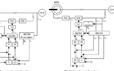
In this section, a proposed model of the system that is based on topology proposed in [22] is used to control the DFIG. This system has two independent controlling sections: the rotor-side converter and the grid-side converter. Since a DC link capacitor is used between two rotor and grid-side convertors, these two convertors can be controlled independently [22].There are different theories to control DFIG by means of these two convertors. In the present method, the reactive power passed through the grid-side converter and the DC link voltage are both controlled by the grid-side convertor. On the other hand, the stator reactive power and the electromagnetic torque are both controlled by the rotor-side convertor. In this system, first quantities are conducted from the abc reference frame to the rotor d-q reference frame; then, the reference signals are generated and finally these signals are returned to the abc frame.
2.1 Rotor-Side Convertor
Considering [23], Eqs. (1) and (2) are used to design the controlling system.
Iranian Journal of Electrical and Electronic Engineering, Vol. 14, No. 4, December 2018 332
2 3
s ds
qr s
ds m s m
L v
i Q
v L L
(1)
3 2
m
e dr ds
s s PL
T i v
L
(2)
Eq. (1) has been used directly. The reference stator reactive power and the d-axis stator voltage have been used to calculate the q-axis stator current. Based on Eq. (2), it can be seen that the d-axis component of the rotor current and electromagnetic torque are related. Thus, this relation is used to measure the d-axis reference quantity of the rotor-current. It is apt to mention that Eq. (2) is not utilized directly and first the fault quantity of the electromagnetic torque is altered to the d-axis reference quantity of the rotor current by means of a PI controller. This process is done to attain a belter controllability. Then, these two rotor reference currents are compared to their actual quantities in d and q axis. After that, the calculated fault is given to two separate PI controllers so that their outputs are the rotor reference voltage in d and q axes. Finally, the scheme of the system is represented in Fig. 1.
2.2 Grid-Side Convertor
Considering [23], Eq. (3) is used to design the controlling system: 1.5 g qg dg Q i v
(3)
Eq. (3) is used to calculate the d-axis reference quantity of the GSC current by applying the reactive power reference quantity of the GSC current by applying the reactive power reference quantity passing through GSC and the d-axis of the GSC voltage. Moreover, a PI controller is used to control a DC link voltage. The input of the mentioned PI controller is the DC link voltage fault and its output is the d-axis reference quantity of the GSC current. Then, these two GSC reference currents are compared to their real quantities in d and q axes and the calculated fault is given to two separate PI controllers that their output is the GSC reference voltage in d and q-axes. Consequently, the system scheme is as Fig. 2.
Further explanations regarding these two control systems are in [23].
3 FRT and LVRT
When there is a fault in a grid, based on the disconnection limitation [24], a turbine have to be connected to the grid for a specific time span. It is done to make sure that the power generation during the usual time of the fault purgation is not reduced. The rapid disconnection of a wind turbine, especially huge wind farms, can affect negatively on the grid. This ability is called FRT. Moreover, based on the grid codes it is
necessary that huge wind farms tolerate the low voltage for a specific drop percent in relation to the nominal voltage and a specific time period. This ability is called LVRT.
DFIG-based wind farms are highly sensitive to the grid changes especially the low-voltage. It is because of this fact that the DFIG stator is directly connected to the grid. During the grid fault or the low-voltage condition, one or more stator voltage phases drop. This phenomenon causes a lot of stator transient current which make a lot of current flow through the rotor and the rotor convertors because of a magnetic couple made between the stator and the rotor. Considering the convertors’ limitation, it is possible that generating convertors controlling commands are not achieved under the rotor high current and it is possible to lose the DFIG control and lead to the temperature failure of the convertors. Even if convertors work within their domains, it is again possible that the stator current gets very unbalanced that causes a torque pulse. This torque pulse makes a sound noise which can highly destruct the rotor shaft, gearbox and vane assemblies.
In research papers, some interactive measures are introduced to boost LVRT and FRT capabilities in DFIG. These measures can be classified into active and passive methods. Passive methods are hardware-based methods which utilize additional equipment. Among these methods, one can refer to vane pitch angle, crowbar methods and an energy capacitor system. On the other hand, active methods take the best advantages of convertors suitable control [25].
In the present article, the proposed hybrid method is an active one which is divided into two parts known as applying the demagnetization control theory and improving controlling coefficients. Based on the demagnetization control theory, when the rotor current exits the permitted domain, it can influence on the basic rotor current by using the band-pass filter and make the current come back to the permitted domain. In this regard, to access more information, one can refer to [10]. Based on the second part of this article, during the fault and low-voltage situation, optimal values of the PI controller coefficients of the rotor-side converter and coefficients which is equal to the demagnetize current have been applied to the controlling system.
4 The Krill Optimization Algorithm
Krill algorithm has been introduced in 2012 to optimize the mathematical models [26]. The krill herd algorithm is categorized as the swarm intelligence algorithm which investigates the collective movements of krill to find food. By applying this algorithm, it is possible to solve those problems which have no precise solution in logical time and find a close and reasonable solution. This algorithm works based on the simulation of a krill herd behaviors and movements to find food. In this algorithm, the minimum distances between any
Iranian Journal of Electrical and Electronic Engineering, Vol. 14, No. 4, December 2018 333
Fig. 1 The rotor-side controller scheme. Fig. 2 Grid-side controller scheme.
given krill to food on one hand and to the centralized population on the other hand are considered as the krill movement objective function. In the krill herd algorithm, a time dependent place is formulized based on three factors:
1. The inductive movements by other krill,
2. Probe to find food,
3. Random movement.
To simulate krill’s behaviors, a herd of krill is generated and their situation is updated based on the following equation:
1
1
d
N
g g g
i i i j j
j
x x v k UP LOW
(4), , ,
g g g g
i I i P i R i
v v v v (5)
In Eq. (4), xi and g represent each krill situation and the
number of iteration respectively. The upper and lower
limits of each controlling variable are shown by UPj and
LOWj. The above speeds are based on krill’s inductive
speed
,g F i
v , probe to find food
,g P i
v and random
movement
,g R i
v . The mathematical realization of
these trends are defined as:
The inductive speed
The influence of neighbor krill on each krill is modeled in this process. Each krill arranges its speed based on the local influence, the objective influence and the repellent influence that formulated as below:
max 1
, , , ,
g g
I i I i I i I I i
v v v (6)
, 1 max 2 n N
i j i j
I i
j w b i j
b b i i
A A x x
A A x x
iter
rand A x
iter
s (7)The local and objective influences are modeled by means of σI,i in an inductive speed. ∂I is an internal
weight of the inductive speed that is between [0, 1]. Ai,
Aw and Ab are the fitness functions of the i-th, the worst
and best krill observed in the population, respectively.
iter and itermax shows the current and the maximum
iteration. The neighbor selection of each krill is determined based on the recognition domain and the situation of each krill in the searching domain. Each krill chooses the closest krill which is in the recognition
domain as its neighbor. The distance among krill (dz) is
determined by using the following equation:
1
1
5 c
N
z i j
j c
d x x
N
(8) Probe to find food
Here, the aim is to update the food searching speed based on the krill memory in finding food. Indeed, each krill updates its speed based on the present and the last food. 1 , max 1 1 ,
0.02 2 1
1 n n N i j j
g b b
P i i i i
N j
j g
P P i
x A iter
v A A x
iter A v
(9)Iranian Journal of Electrical and Electronic Engineering, Vol. 14, No. 4, December 2018 334
Random movement
Along with the optimization process, the population diversity is ensured by the random movement. Its modelling is as below:
max ,
g
R i R
v v (10)
In Eq. (10), vRmax is the maximum scattering speed
that falls in [0.001, 0.002] span. ϑ represents the random
direction vector that is in [-1, 1].
To access the optimum and to increase the convergence speed, the genetic algorithm operators (Crossover and Mutation) are used in krill algorithm.
5 Implementation 5.1 Optimization
As mentioned, the aim is to arrange PI controllers’ coefficients existing in RSC and arrange coefficients equalized to the demagnetize current such that the LVRT and FRT capabilities of the system are enhanced. Table 1 defines the optimization parameters.
To arrange optimization parameters, the krill algorithm is used that is a three-objective in this article. The used objectives include sum of squares of the three PI controllers’ inputs existing in the RSC controlling system through the time.
2
1
2
1
t e t t
f T t dt
(11)
2
1
2
2 ,
t r d t t
f i t dt
(12)
2
1
2
3 ,
t r q t t
f i t dt
(13)As it is known, parameters of PI controllers must be set such that the fault of the controllers’ inputs be close to zero as much as possible. Therefore, here, the optimization problem is a minimization three-objective problem that its output is like a 3 dimension pareto. This algorithm is used in seven different states which are introduced in Table 2; consequently, by applying this algorithm in these states, sought parameters are calculated.
First, state 1 is performed in which x7 and x8
optimization parameters are not considered and just parameters of PI controllers have been used. Then, results of this optimization have been utilized in PI controllers during those spans in which no fault or low-voltage is occurred. As a result, in states 2 to 7, optimization parameters have merely been used when any fault or low-voltage occurs. Considering above-mentioned facts, in Eqs. (7)-(9), t1 and t2 values can be
considered as: in state 1, t1 = 0 and t2 = 2, in states 2, 3
and 4, t1 = 1 and t2 = 1.1, in states 5, 6 and 7, t1 = 1 and
t2 = 1.5.
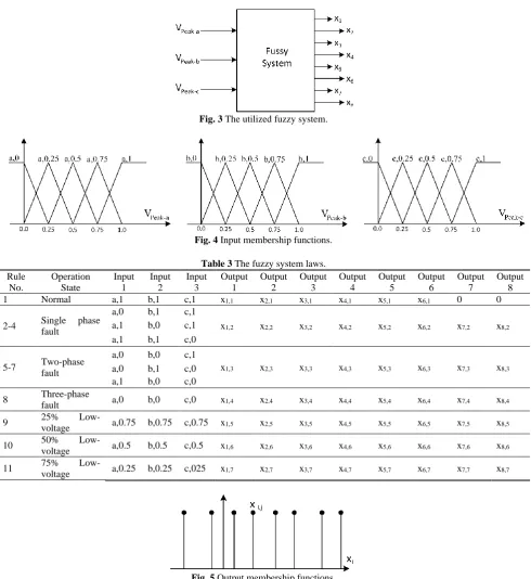
5.2 Fuzzy System
Up to now, optimization parameters are calculated for seven states off-linely. Now, the fuzzy logic is used to on-linely arrange the controlling system’s parameters. This fuzzy system has three inputs and eight outputs. Inputs are stator three-phase voltage peak values and outputs are optimized parameters. Fig. 3 represent this system simply. Consequently, considering the applied conditions which are calculated by the stator three-phase voltage peak, parameters of the control system find out.
Table 1 Optimization parameters. Parameter Definition
x1 Kp coefficient (PI controller with electromagnetic torque error as input and d-axis rotor current as output)
x2 Ki coefficient (PI controller with electromagnetic torque error as input and d-axis rotor current as output)
x3 Kp coefficient (PI controller with d-axis rotor current error as input and d-axis rotor voltage as output)
x4 Ki coefficient (PI controller with d-axis rotor current error as input and d-axis rotor voltage as output)
x5 Kp coefficient (PI controller with q-axis rotor current error as input and q-axis rotor voltage as output)
x6 Ki coefficient (PI controller with q-axis rotor current error as input and q-axis rotor voltage as output)
x7 d-axis demagnetization current
x8 q-axis demagnetization current
Table 2 States of applying optimization. State No. Operation Type
1 Normal operation
2 Single phase fault to ground (1 < t < 1.1) 3 Two-phase fault to ground (1 < t < 1.1) 4 Three-phase fault to ground (1 < t < 1.1) 5 25% Low-voltage (1 < t < 1.5)
6 50% Low-voltage (1 < t < 1.5) 7 75% Low-voltage (1 < t < 1.5)
Iranian Journal of Electrical and Electronic Engineering, Vol. 14, No. 4, December 2018 335
Fig. 3 The utilized fuzzy system.
Fig. 4 Input membership functions.
Table 3 The fuzzy system laws. Rule
No.
Operation State
Input 1
Input 2
Input 3
Output 1
Output 2
Output 3
Output 4
Output 5
Output 6
Output 7
Output 8
1 Normal a,1 b,1 c,1 x1,1 x2,1 x3,1 x4,1 x5,1 x6,1 0 0
2-4 Single phase fault
a,0 b,1 c,1
x1,2 x2,2 x3,2 x4,2 x5,2 x6,2 x7,2 x8,2
a,1 b,0 c,1 a,1 b,1 c,0
5-7 Two-phase fault
a,0 b,0 c,1
x1,3 x2,3 x3,3 x4,3 x5,3 x6,3 x7,3 x8,3
a,0 b,1 c,0 a,1 b,0 c,0
8 Three-phase
fault a,0 b,0 c,0 x1,4 x2,4 x3,4 x4,4 x5,4 x6,4 x7,4 x8,4
9 25%
Low-voltage a,0.75 b,0.75 c,0.75 x1,5 x2,5 x3,5 x4,5 x5,5 x6,5 x7,5 x8,5
10 50%
Low-voltage a,0.5 b,0.5 c,0.5 x1,6 x2,6 x3,6 x4,6 x5,6 x6,6 x7,6 x8,6
11 75%
Low-voltage a,0.25 b,0.25 c,025 x1,7 x2,7 x3,7 x4,7 x5,7 x6,7 x7,7 x8,7
Fig. 5 Output membership functions.
To use this system, it is necessary to define membership functions and the fuzzy system laws. In Figs. 4 and 5 and Table 3, the input membership functions, output membership functions and used laws are represented.
In Fig. 5 and Table 3, xi is the i-th output of the fuzzy
system and xi,j equals to the optimized quantity of xi
variable in the j-th utilization state. As observed, the output membership functions are represented as a singleton and the input membership functions are shown as a triangle.
5.3 General Structure
To reach at a better understanding of the proposed structure, its general scheme is shown in Fig. 6. As one can see, the stator voltage values are given to the three-phase controller and the optimized coefficients of x1 to
x6 are given to the PI controllers. Consequently, x7 and
x8 coefficients are summed up with the rotor current
faults.
Iranian Journal of Electrical and Electronic Engineering, Vol. 14, No. 4, December 2018 336
Fig. 6 The general scheme of the proposed system.
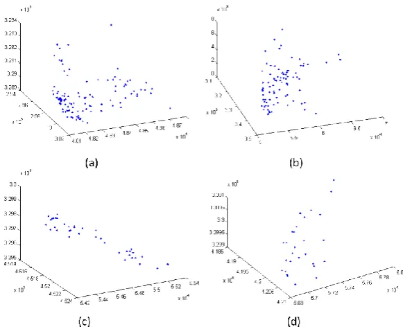
Fig. 7 The output pareto of krill algorithm: a) state 1, b) state 2, c) state 5 and d) state 7.
6 Results
As it mentioned, the optimization algorithm is a three-objective and its output is as a 3 dimension pareto and as the algorithm is done on the 7 states, there are 7 paretos. Results of performing krill algorithm and the output paretos for sample states 1, 2, 5 and 7 are represented in Fig. 7.
Optimized parameters in different states are shown in Table 4 considering the calculated point and the selection from the pareto.
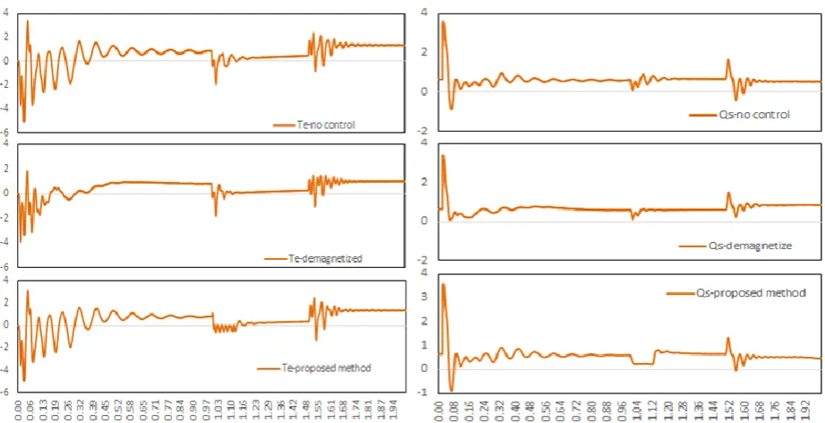
As mentioned in the previous sections, the RSC
controls the electromagnetic torque and the stator reactive power. First to justify the proposed method, its performance is compared with the demagnetize method. To do so, results of the electromagnetic torque and the stator reactive power are shown in Fig. 8 and Fig. 9 for conditions of the uncontrolled, demagnetized and proposed method for two-phase fault and 50% low voltage states, respectively.
Considering Figs. 8 and 9, it seems that while applying the proposed method the electromagnetic torque and the stator reactive power have less jump and
Iranian Journal of Electrical and Electronic Engineering, Vol. 14, No. 4, December 2018 337
Table 4 The optimized parameters in different utilization states.
Operation State x1 x2 x3 x4 x5 x6 x7 x8
Normal -1.95717 -2 2.535847 14.71155 5.684226 0.076487 0 0
Single phase fault
-1.9489 17.69 2.2711 43.349 0.98194 -1.6066 -0.27961 0.2743
Two-phase fault -2 0.22944 5.8842 37.475 7.1124 41.547 -0.33113 0.14263
Three-phase fault
36.391 22.56 14.682 34.997 -0.03323 44.811 -0.68635 -0.64283
25%
Low-voltage
41.48438 29.13214 15.44657 13.21094 28.3109 34.39113 -1 -0.89716
50%
Low-voltage
17.51973 33.86995 17.73002 37.27866 43.84739 42.86396 -1 -0.44805
75%
Low-voltage
50 11.48706 24.43795 33.77883 7.555173 50 -0.99998 -0.19065
Fig. 8 The electromagnetic torque and the stator reactive power in two-phase fault state and in conditions of uncontrolled, demagnetized and the proposed method.
Fig. 9 The electromagnetic torque and the stator reactive power in 50% low voltage state and in conditions of uncontrolled, demagnetized and the proposed method.
Iranian Journal of Electrical and Electronic Engineering, Vol. 14, No. 4, December 2018 338
more stability speed.
By paying attention to Figs. 8 and 9, one can better detect the performance of the proposed method in relation to the demagnetized method. In the following Figs. 10 and 11, the electromagnetic torque and the stator reactive power are shown under conditions 2-7 represented in Table 2. Each state holds two diagrams:
In the first diagram normal state’s coefficients of the PI controllers and the demagnetize current are considered and in the second diagram the optimized coefficients and currents related to each state are used based on Table 3.
Considering above results, the following propositions are understood:
Fig. 10 The electromagnetic torque in the normal condition and in the proposed method condition under a) single phase fault, b) two-phase fault, c) three-two-phase fault, d) 25% low voltage, e) 50% low voltage and f) 75% low voltage states.
Fig. 11 The stator reactive power in the normal condition and in the proposed method condition under a) single phase fault, b) two-phase fault, c) three-two-phase fault, d) 25% low voltage, e) 50% low voltage and f) 75% low voltage states
Iranian Journal of Electrical and Electronic Engineering, Vol. 14, No. 4, December 2018 339
In Figs. 10(a)-(c) which represent the
electromagnetic torque under a fault in 1s to 1.1s time span, it is observed that when the optimized coefficients by the algorithm are used, both the torque ripple and jump are reduced and the oscillations damped earlier.
In Figs. 10(d)-(f) which represent the
electromagnetic torque under a low voltage in 1s to 1.5s time span, it is observed that applying optimized coefficients get the torque change peak reduced.
In Figs. 11(a)-(c) which represent the stator
reactive power under a fault in 1s to 1.1s time span, it is observed that when the optimized coefficients by the algorithm are used, both the torque ripple and jump are reduced and the oscillations damped earlier
In Figs. 10(d)-(f) which represent the stator
reactive power under a low voltage in 1s to 1.5s time span, it is observed that applying optimized coefficients get the torque change peak reduced. The torque peak reduction makes the suddenly mechanical pressure reduction on the turbine’s components and gets the occurrence of events decreased. The reduction in the torque oscillation damping time makes removing changes faster and has the turbine operation smoothly. The reactive power peak reduction also reduces the negative effects on the grid voltage. Moreover, the reactive power oscillation damping time reduction gets the voltage more stable and helps the grid to encounter with the fault or the low voltage.
7 Conclusion
Considering the rapid development of wind energy,
designing controlling systems with the better
performance has been highly noticed in recent years. In designing DFIG controlling systems, improving LVRT and FRT are the most important factors. Therefore, in the present article a hybrid method based on the krill algorithm and the fuzzy logic is proposed in that the demagnetization controlling theory is applied as well. The proposed method is an active method which can improve the DFIG performance by changing the controlling coefficients and the demagnetization effect when any fault or any low-voltage occurs. Simulation results of the proposed method have shown that the method reduces the changes peak and the changes mortality time, consequently, increases the DFIG system stability at the time of a fault or a low-voltage. Optimized coefficients have been calculated off-line. However, controlling and applying coefficients to the controlling system have done on-line. Therefore, the proposed method is a high performance method for the practical applications.
References
[1] A. D. Hansen, F. Iov, F. Blaabjerg and
L. H. Hansen, “Review of contemporary wind
turbine concepts and their market penetration,” Wind
Engineering, Vol. 28, No. 3, pp. 247–263, 2004.
[2] J. A. Baroudi, V. Dinavahi and A. M. Knight, “A
review of power converter topologies for wind
generators,” Renewable Energy, Vol. 32, No. 14,
pp. 2369–2385, 2007.
[3] M. I. Daoud, A. M. Massoud, A. S. Abdel-Khalik,
A. Elserougi and S. Ahmed, “A flywheel energy storage system for fault ride through support of grid-connected VSC HVDC-based offshore wind farms,”
IEEE Transactions on Power Systems, Vol. 31, No. 3, pp. 1671–1680, 2016.
[4] R. Cardenas, R. Peña, S. Alepuz and G. Asher,
“Overview of control systems for the operation of
DFIGs in wind energy applications,” IEEE
Transactions on Industrial Electronics, Vol. 60, No. 7, pp. 2776–2798, 2013.
[5] J. López, E. Gubía, E. Olea, J. Ruiz and
L. Marroyo, “Ride through of wind turbines with doubly fed induction generator under symmetrical
voltage dips,” IEEE Transactions on Industrial
Electronics, Vol. 56, No. 10, pp. 4246–4254, 2009.
[6] L. G. Meegahapola, T. Littler and D. Flynn,
“Decoupled-DFIG fault ride-through strategy for enhanced stability performance during grid faults,”
IEEE Transactions on Sustainable Energy, Vol. 1, No. 3, pp. 152–162, 2010.
[7] Q. Huang, X. Zou, D. Zhu and Y. Kang, “Scaled
current tracking control for doubly fed induction generator to ride-through serious grid faults,” IEEE Transactions on Power Electronics, Vol. 31, No. 3, pp. 2150–2165, 2016.
[8] J. Liang, W. Qiao and R. G. Harley, “Feed-forward
transient current control for low-voltage
ride-through enhancement of DFIG wind turbines,” IEEE
Transactions on Energy Conversion, Vol. 25, No. 3, pp. 836–843, 2010.
[9] T. D. Vrionis, X. I. Koutiva and N. A. Vovos, “A genetic algorithm-based low voltage ride-through control strategy for grid connected doubly fed
induction wind generators,” IEEE Transactions on
Power Systems, Vol. 29, No. 3, pp. 1325–1334, 2014.
[10]D. Xiang, L. Ran, P. J. Tavner and S. Yang,
“Control of a doubly fed induction generator in a
wind turbine during grid fault ride-through,” IEEE
Transactions on Energy Conversion, Vol. 21, No. 3, pp. 652–662, 2006.
Iranian Journal of Electrical and Electronic Engineering, Vol. 14, No. 4, December 2018 340
[11]S. Xiao, G. Yang, H. Zhou and H. Geng, “An
LVRT control strategy based on flux linkage
tracking for DFIG-based WECS,” IEEE
Transactions on Industrial Electronics, Vol. 60, No. , pp. 2820–2832, 2013.
[12]P. H. Huang, M. S. El Moursi, W. Xiao and
J. L. Kirtley Jr, “Novel fault ride-through
configuration and transient management scheme for
doubly fed induction generator,” IEEE Transactions
on Energy Conversion, Vol. 28, No. 1, pp. 86–94, 2013.
[13]P. S. Flannery and G. Venkataramanan,
“Unbalanced voltage sag ride-through of a doubly fed induction generator wind turbine with series
grid-side converter,” IEEE Transactions on Industry
Applications, Vol. 45, No. 5, pp. 1879–1887, 2009.
[14]J. Yang, J. E. Fletcher and J. O’Reilly, “A series-dynamic-resistor-based converter protection scheme for doubly-fed induction generator during various
fault conditions,” IEEE Transactions on Energy
Conversion, Vol. 25, No. 2, pp. 422–432, 2010.
[15]J. G. Nielsen and F. Blaabjerg, “A detailed
comparison of system topologies for dynamic
voltage restorers,” IEEE Transactions on Industry
Applications, Vol. 41, No. 5, pp. 1272–1280, 2005.
[16]P. Kanjiya, B. B. Ambati and V. Khadkikar, “A
novel fault-tolerant DFIG-based wind energy conversion system for seamless operation during
grid faults,” IEEE Transactions on Power Systems,
Vol. 29, No. 3, pp. 1296–1305, 2014.
[17]A. H. Kasem, E. El-Saadany, H. El-Tamaly and
M. Wahab, “An improved fault ride-through strategy for doubly fed induction generator-based wind
turbines,” IET Renewable Power Generation, Vol. 2,
No. 4, pp. 201–214, 2008.
[18]M. Mohseni and S. M. Islam, “Transient control of
DFIG-based wind power plants in compliance with
the Australian grid code,” IEEE Transactions on
Power Electronics, Vol. 27, No. 6, pp. 2813–2824, 2012.
[19]Y. W. Shen, D. P. Ke, W. Qiao, Y. Z. Sun,
D. S. Kirschen and C. Wei, “Transient
reconfiguration and coordinated control for power converters to enhance the LVRT of a DFIG wind
turbine with an energy storage device,” IEEE
Transactions on energy conversion, Vol. 30, No. 4, pp. 1679–1690, 2015.
[20]D. Xie, Z. Xu, L. Yang, J. Østergaard, Y. Xue and
K. P. Wong, “A comprehensive LVRT control strategy for DFIG wind turbines with enhanced
reactive power support,” IEEE Transactions on
Power Systems, Vol. 28, No. 3, pp. 3302–3310, 2013.
[21]S. B. Naderi, M. Negnevitsky, A. Jalilian,
M. T. Hagh and K. M. Muttaqi, “Optimum resistive type fault current limiter: An efficient solution to achieve maximum fault ride-through capability of fixed-speed wind turbines during symmetrical and
asymmetrical grid faults,” IEEE Transactions on
Industry Applications, Vol. 53, No. 1, pp. 538–548, 2017.
[22]P. Szcześniak and J. Kaniewski, “Power electronics
converters without DC energy storage in the future
electrical power network,” Electric Power Systems
Research, Vol. 129, pp. 194–207, 2015.
[23]B. Wu, Y. Lang, N. Zargari and S. Kouro, Power
conversion and control of wind energy systems. John Wiley & Sons, 2011.
[24]W. Guo, L. Xiao and S. Dai, “Enhancing
low-voltage ride-through capability and smoothing output power of DFIG with a superconducting fault-current limiter–magnetic energy storage system,”
IEEE Transactions on Energy Conversion, Vol. 27, No. 2, pp. 277–295, 2012.
[25]A. M. Haidar, K. M. Muttaqi and M. T. Hagh, “A
coordinated control approach for DC link and rotor crowbars to improve fault ride-through of
DFIG-based wind turbine,” IEEE Transactions on Industry
Applications, Vol. 53, No. 4, pp. 4073–4086, 2017.
[26]A. H. Gandomi and A. H. Alavi, “Krill herd: a new
bio-inspired optimization algorithm,”
Communications in Nonlinear Science and Numerical Simulation, Vol. 17, No. 12, pp. 4831– 4845, 2012.
H. Ahmadi was born in Bushehr, Iran, in 1986. She received the B.Sc. degree in Electronic Technology Engineering from Lian Institute of Higher Education, Bushehr, Iran, in 2013, and M.Sc. degree from Shiraz University of Technology, Shiraz, Iran, in 2016. Her research fields cover: Power Electronic, Wind Energy, Fuzzy Logics and Optimization.
A. Rajaei (IEEE M’12) was born in Jahrom, Iran. He received the M.Sc. and the Ph.D. degrees in Electrical Engineering from Tarbiat Modares University, Tehran, Iran, in 2009 and 2013, respectively. He is currently an Assistant Professor with the Shiraz University of Technology, Shiraz, Iran. His main research interests include renewable energy resources, power converters, electric vehicles, and motor drive systems.
Iranian Journal of Electrical and Electronic Engineering, Vol. 14, No. 4, December 2018 341
M. Nayeripour was born in Shiraz, Iran. He received his Ph.D. in Electrical Engineering from Tarbiat Modares University, Tehran, Iran and is currently a Professor at Shiraz University of Technology, Shiraz, Iran. His main interests is smart grids and their control issues.
M. Ghani Varzaneh was born in Isfahan, Iran in 1988. He received his B.Sc. and M.Sc. in Electrical Engineering from University of Isfahan and Islamic Azad University in 2012 and 2014, respectively. His interests are power electronics converters design, simulation, control and manufacturing. He is currently a Ph.D. student in Power Electronics field at Shiraz University of Technology.
© 2018 by the authors. Licensee IUST, Tehran, Iran. This article is an open access article distributed under the terms and conditions of the Creative Commons Attribution-NonCommercial 4.0 International (CC BY-NC 4.0) license (https://creativecommons.org/licenses/by-nc/4.0/).