© 2019, IRJET | Impact Factor value: 7.211 | ISO 9001:2008 Certified Journal
| Page 2850
GRID INTERFACING OF PV/BATTERY HYBRID ENERGY CONVERSION
SYSTEM WITH POWER QUALITY IMPROVEMENT FEATURES BASED ON
INTERLEAVED BOOST CONVERTER
Kopin Bharti
1, Ravi Raj
2, Mritunjay Kumar
31
M.Tech Student, EEE, BIT, Muzaffarnagar, U.P, (India)
2Asst.Professor, EEE, BIT, Muzaffarnagar, U.P, (India)
3
Asst. Professor, C.S.E, BU, Ajmer, Rajasthan, (India)
---***---
Abstract -
This Paper presents the Grid interfacing of PV/Battery Hybrid energy conversion system with power quality enhancement features based on interleaved boost converter. The normally utilized sustainable power source frameworks incorporate photovoltaic cells and energy components. An appropriate DC-DC converter is proposed for exceptionally productive sustainable power source frameworks. Interleaved Boost Converter (IBC) topology is examined in this paper for sustainable power source applications. Network combination of photograph voltaic (PV)/Battery half breed vitality transformation framework with (I) multi-useful highlights of miniaturized scale lattice side bidirectional voltage source converter (μGVSC) (ii) tight voltage guideline ability of battery converter (iii) MPPT following execution of high addition coordinated fell lift (HGICB) dc-dc Converter with quadratic increase and less current swell are exhibited in this paper. The upsides of interleaved support converter contrasted with the traditional lift converter are low information current swell, high productivity, quicker transient reaction, decreased electromagnetic discharge and improved unwavering quality The battery vitality stockpiling framework (BESS) is controlled to adjust the power between PV age and utility lattice The waveforms of info, inductor current swell and yield voltage swell are gotten utilizing MA TLAB/SlMULINK. The structure conditions for IBC have been exhibited.Key Words---
μGVSC, HGICB, Interleaved boost
converter (IBC)
.I. INTRODUCTION
Fossil fuels are energy sources such as coal, oil and natural gas. The world practically relies upon the. Supply of petroleum product for vitality. In any case, the normal issue is that petroleum products are running out. It would take a great many years to totally reestablish the non-renewable energy sources that we have utilized in only a couple of decades.
This implies petroleum products are non-sustainable wellsprings of vitality. Sustainable power
source comes in as a goals for this worldwide issue. Sustainable power source is any normal source that can recharge itself normally over a short measure of time. Sustainable power source originates from numerous regularly referred to sources, for example, sunlight based power, wind, running water and geothermal vitality. Sustainable power sources are awesome choices since they are boundless. Likewise another extraordinary profit by utilizing sustainable power source is that a considerable lot of them don't dirty our air and water, the manner in which consuming non-renewable energy sources does. Any such sustainable power source framework requires an appropriate converter to make it productive. Interleaved help converter is one such converter that can be utilized for these applications.
Numerous DC-DC converter topologies are accessible to follow the MPP in PV producing framework. Course association of ordinary converters gives more extensive transformation proportions [1]. One of the real favorable circumstances of these converters is a high addition and low current swell. Be that as it may, this arrangement has a disadvantage that the complete proficiency may turn out to be low if the quantities of stages are high, attributable to control misfortunes in the exchanging gadgets [1]. A quadratic converter arrangement is likewise accessible that utilizations single switch and accomplishes quadratic increase [1]. A fascinating alluring converter topology is a high increase coordinated fell lift converter having n-converters associated in course utilizing a solitary dynamic switch. The precariousness brought about by the course structure is kept away from, when contrasted and the ordinary course support converter [1]. This class of converters can be utilized just when the required number of stages isn't huge, else the proficiency will be diminished. In any case, this class of converters for PV applications isn't accounted for in the specialized writing.
© 2019, IRJET | Impact Factor value: 7.211 | ISO 9001:2008 Certified Journal
| Page 2851
For example, synchronous reference hypothesis, control balance hypothesis, and direct current vector control [3], [4], for control of μG-VSC in smaller scale lattice application. These calculations require complex facilitate changes, which is lumbering. Contrasted with the control systems referenced over, the Instantaneous symmetrical segment based control proposed in this paper for miniaturized scale framework applications is straightforward in detailing, stays away from translation of immediate responsive power and needs no intricate changes.
The Interleaved lift converter has high voltage venture up, decreased voltage swell at the yield, low exchanging misfortune, diminished electromagnetic impedance and quicker transient reaction. Additionally, the enduring state voltage swells at the yield capacitors of mc are decreased. In spite of the fact that IBC topology has more inductors expanding the multifaceted nature of the converter contrasted with the regular lift converter it is favored due to the low swell substance in the info and yield sides. So as to lessen this unpredictability, this paper examines the advantages of coupled, uncoupled and contrarily inductors for mc. Itemized investigation has been done to think about the swell substance of all the three kinds of the converter. The reasonable mc for energy component applications is proposed [5]. Gating
heartbeats are created utilizing beat generator. Reenactments have been performed to approve the ideas.
This paper is organized as pursues: In segment 2, framework portrayal. In segment 3, modelings of different parts are exhibited. The proposed control systems for HGICB DC-DC Converter, Interleaved Boost Converter (IBC) and μG-VSC are talked about in segment 4. The reenactment results are introduced in area 5. With finishing up comments in area 6.
II. SYSTEM DESCRIPTION
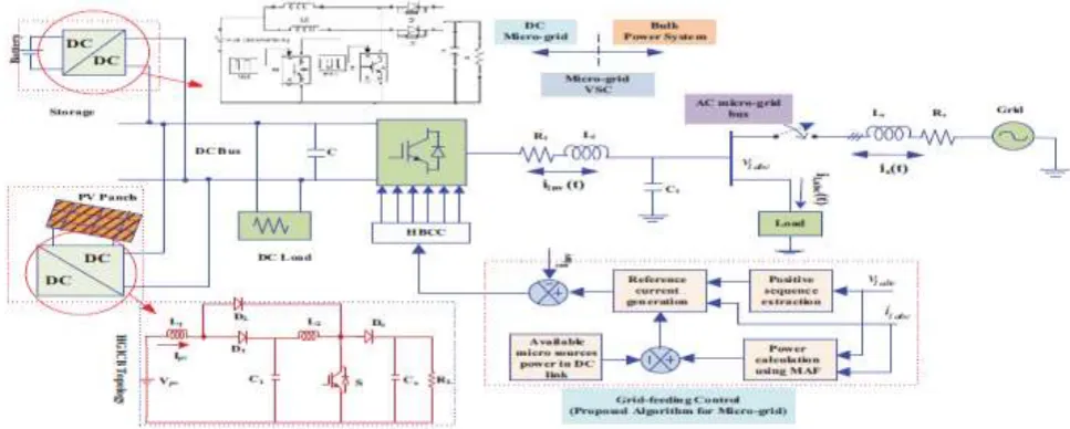
[image:2.595.54.538.419.613.2]The visualized framework comprises of a PV/Battery half and half framework with the principle matrix interfacing with non-direct and lopsided burdens at the PCC as appeared in the Fig. 1. The photovoltaic framework is demonstrated as nonlinear voltage sources [6]. The PV exhibit is associated with HGICB dc-dc converter and interleaved help converter are appeared in Fig. 1, which are coupled at the dc side of a μG-VSC. The HGICB dc converter is associated with the PV exhibit fills in as MPPT controller and battery converter is utilized to manage the power stream among dc and air conditioning side of the framework.
Fig -1: Hybrid Energy Conversion System under consideration
III. MODELING AND CONTROL
A. PV Array Model
The mathematical model of PV system referred in [6] is used in this work.
B. Operation of IBC
© 2019, IRJET | Impact Factor value: 7.211 | ISO 9001:2008 Certified Journal
| Page 2852
Fig -2: Circuit diagram of a two phase uncoupled IBC
Since two stages are utilized the swell recurrence is multiplied and results in decrease of voltage swell at the yield side. The information current swell is likewise diminished by this course of action.
At the point when door heartbeat is given to the principal stage for a period t1, the current over the inductor rises and vitality is put away in the inductor. At the point when the gadget in the primary stage is killed, the vitality put away is moved to the heap through the yield diode D. The inductor and the capacitor fill in as voltage sources to stretch out the voltage gain and to lessen the voltage weight on the switch. The expanding current rate over the yield diode is constrained by inductances in the stages. Door heartbeat is allowed to the second stage during the time t1 to t2 when the gadget in the main stage is OFF. At the point when the gadget in the stage two is ON the inductor charges for a similar time and moves vitality to the heap likewise as the principal stage. In this manner the two stages feed the heap consistently.
IV. DESIGN METHODOLOGY OF IBC
The structure procedure for a wide range of IBC's require a determination of legitimate estimations of inductor, capacitor and appropriate decision of the power semiconductor gadgets to decrease the exchanging losses[8]. The means associated with structuring IBC are as per the following [9]:
• Decision of obligation proportion and number of stages
• Selection of Inductor esteems
• Selection of intensity semiconductor switches
• Design of yield channel
1) Selection of obligation proportion and number of stages two stage IBC is picked since the swell substance lessens with increment in the quantity of stages. In the event that the quantity of the stages is expanded further,
absent much decline in the swell substance, the intricacy of the circuit increments without a doubt, consequently expanding the expense of execution. Henceforth, as a tradeoff between the swell substance and the expense and multifaceted nature, number of stages is picked as two. The quantity of inductors, switches and diodes are same as the quantity of stages and exchanging recurrence is same for every one of the stages.
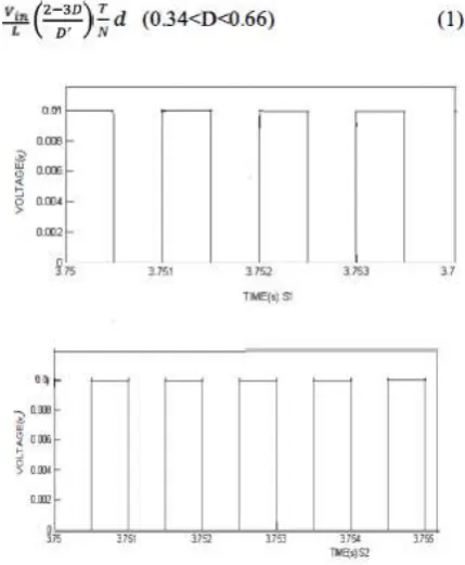
Fig –3: Switching pattern for two phase IBC
The info current swell can be zero at explicit obligation proportions which are products of l/N, where N represents the no of stages. Here the quantity of stages is two accordingly the obligation proportion is taken as 0.5. The exchanging example is appeared in Figure 3.
A. Age of reference flows for μG-VSC
The fundamental point of the μG-VSC control is to drop the impacts of uneven and symphonious parts of the nearby burden, while providing pre-indicated measure of genuine and receptive forces to the heap. Upon effectively meeting this target, the framework current ig will at that point be adjusted thus will be the PCC voltage vp given, network voltage vg is adjusted. Give us a chance to indicate the three stages by the subscripts a, b and c. Since ig is adjusted, we can compose:
iga + igb + igc = 0 (2)
[image:3.595.329.544.200.461.2]© 2019, IRJET | Impact Factor value: 7.211 | ISO 9001:2008 Certified Journal
| Page 2853
ig,abc + iinv,abc = iL,abc . (3)
Therefore, from (2) and (3), we can write as:
iinv,a + iinv,b + iinv,c = iL,a + iL,b + iL,c . (4)
Since ig is adjusted because of the activity of the compensator, the voltage vp will likewise wind up adjusted. Thus, the prompt genuine forces Pg will be equivalent to its normal segment. Along these lines, we can compose
[image:4.595.49.266.257.362.2]Pg = vpa iga + vpb igb + vpc igc (5)
TABLE I SYSTEM PARAMETERS
Solving above equations, the μG-VSC reference currents are obtained as follows:
and Qs = Ql − Qμs, and by substituting β Ps = √Qs 3 into
the equation (9), the modified G-VSC reference current equations in terms of active and reactive components are obtained as:
In conditions (6) and (7), Pμs, Plavg, and Ql are the accessible small scale source control, normal burden power, and burden responsive power separately. Ploss indicates the exchanging misfortunes and ohmic misfortunes in genuine compensator. The term Plavg is acquired utilizing a moving normal channel of one cycle window of time T in short order.
V. SIMULATION RESULTS
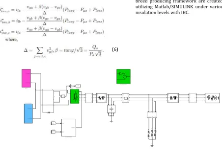
[image:4.595.39.492.397.712.2]The proposed control procedures for PV cross breed producing framework are created and recreated utilizing Matlab/SIMULINK under various sun oriented insolation levels with IBC.
Fig -4: Proposed SIMULINK circuit
(7)
© 2019, IRJET | Impact Factor value: 7.211 | ISO 9001:2008 Certified Journal
| Page 2854
Irradiance (kw/m^2)
Load Currents (A)
Grid Currents (A)
Fig -5: Simulation results using proposed control approach for Micro-grid side VSC: (a) Insolation Changes (b) Load currents (c) Grid currents (d) μG-VSC currents.
VI. CONCLUSIONS
Interleaved boost converter has so many advantages and is a suitable converter for renewable energy applications. The presentation of PV/Battery mixture vitality change framework has been shown with the utilization of altered prompt symmetrical segments hypothesis to μG-VSC proposed in this paper, an effective control procedure is likewise proposed for battery interleaved support converter to direct the dc transport voltage firmly, under fluctuating sun powered insolation and dc burden conditions. HGICB converter topology is utilized to follow the MPPT with high increase and less current swell. The μG-VSC can infuse the created power into the framework alongside consonant and responsive power remuneration for unequal non-direct burden at the PCC at the same time. The framework works
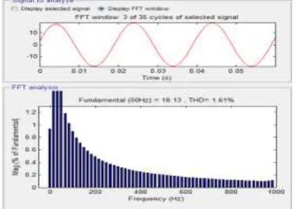
palatably under unique conditions. The reproduction results under a lopsided non-direct burden with current THD of 12% affirm that the μGVSC can successfully infuse the created dynamic
Power along with power quality improvement features and thus, it maintains a sinusoidal and UPF current at the grid side with THD of 1.61%.
REFERENCES
[1] W. Li and X. He, ―Review of nonisolated high-step-up dc/dc converters in photovoltaic grid-connected applications,‖ IEEE Trans. Ind. Electron., vol. 58, no. 4, pp. 1239 –1250, Apr. 2011.
[2] J. Rocabert, A. Luna, F. Blaabjerg, and P. Rodri andguez,―Control of power converters in ac microgrids,‖ IEEE Trans. Power Electron., vol.27, no. 11, pp. 4734 –4749, Nov. 2012.
[3] R. Kadri, J.-P. Gaubert, and G. Champenois, ―An improved maximum power point tracking for photovoltaic grid-connected inverter based on voltage-oriented control,‖ IEEE Trans. Ind. Electron., vol. 58, no. 1, pp. 66 –75, Jan. 2011.
[4] S. Zhang, K.-J. Tseng, D. Vilathgamuwa, T. Nguyen, and X.-Y. Wang,―Design of a robust grid interface system for pmsg-based wind turbine generators,‖ IEEE Trans. Ind. Electron., vol. 58, no. 1, pp. 316–328, Jan. 2011.
[5] Choe, G.Y; Kang, H.S; Lee, B.K; and Lee, W.L. "Design consideration of Interleaved Converters for fuel cell applications", in Proc. International conference on Electrical machines and Systems, Seoul, 2007, pp.238 -243.
[6] A.Chatterjee, A. Keyhani, and D. Kapoor, ―Identification of photovoltaic source models,‖ IEEE Trans. Energy Convers., vol. 26, no. 3, pp. 883 –889, Sept. 2011.
[image:5.595.333.545.151.300.2]© 2019, IRJET | Impact Factor value: 7.211 | ISO 9001:2008 Certified Journal
| Page 2855
Interleaved Boost Converter with Coupled Inductors," in Proc. IEE Electronics Power Application, Vol. 152, No. 3, 2005, pp. 584-594.
[8] Lee, .P; Lee, .Y; Cheng, .DKW; and Liu, X. "Steady-state analysis of an interleaved boost converter with coupled inductors", IEEE Trans. on Industrial Electronics, 47, 2000, pp. 787-795.
[9] Dahono, P.A; Riyadi, S; Mudawari, A; and Haroen, Y."Output ripple analysis of multiphase DC-DC converter", in Proc. IEEE International Conference on Power Electrical and Drive Systems,
Hong Kong, 1999.
[10] Dahono, P.A; Riyadi, S; Mudawari, A; and Haroen, Y."Output ripple analysis of multiphase DC-DC converter", in Proc. IEEE International Conference on Power Electrical and Drive Systems, Hong Kong, 1999.
[11] Veerachary, M; Senjyu, T; and Uezato, K. "Small-signal analysis of interleaved dual boost converter", International Journal of circuit theory and applications, Vol.29, Issue 6, 2001, pp. 575 - 589.
[12] Laszlor, H; Brian, T; Irving, M; Milan and Jovanovic. "ClosedLoop Control Methods for Interleaved DCMlCCM Boundary Boost PFC Converters," in Proc. IEEE Applied Power Electronics Conference, 2009, pp. 991-997.
[13] Thounthong, P; Sethakul,P; Rael,S; and Davat,B. "Design and implementation of 2- phase interleaved boost converter for fuel cell power source," in Proc. International Conference on Power Electronics, Machines, and Drives, PEMD 2008, pp. 91-95.
[14]M.Harinee, V.S.Nagarajan, Dimple, R.Seyezhai, Dr.B.L.Mathur. "Modeling and design of fuel cell based interleaved boost converter". Electrical Energy Systems (ICEES), 2011 1st International Conference on Year:
2011, pp. 72 - 77
[15] R. Seyezhai and B.L. Mathur "Analysis, Design and Experimentation of Interleaved Boost Converter for Fuel Cell Power Source" International Journal of Research and Reviews in Information Sciences (IJRRlS) Vol. 1, No. 2, June 2011 ISSN: 2046-6439 Copyright © Science Academy Publisher, United Kingdom
[16] R.Seyezhai, "Design Consideration of Interleaved Boost Converter for Fuel Cell Systems", international journal of advanced engineering sciences and technologies, Vol No. 7, Issue No. 2, pp. 323 - 329.
[17] P. A. Dahono, S. Riyadi, A. Mudawari, and Y. Haroen, "Output ripple analysis of multiphase DC-DC converter," IEEE Power Electr. And Drive Systems (PEDS), pp.626-631, 1999.
[18] Y. Hu et aI., "Characteristics analysis of two-channel interleaved boost converter with integrated coupling inductors," in Proc. IEEE Power Electronics Specialists Con!, Jun. 2006.
[18] Xu, .H; Qiao, .E; Guo, .X; Wen, .X; and Kong, L. "Analysis and Design of High Power Interleaved Boost Converters for Fuel Cell Distributed Generation System", in Proc. IEEE Power.
[19] Wai, R.J; and Duan; .R.Y. "High step-up converter with coupled-inductor," IEEE Trans. Power Electronics, Vol. 20, No.5, pp. 1025-1035, 2005.