OPTIMAL HARDENABILITY STEEL FOR ANY SIZE AND FORM OF MACHINE COMPONENTS TO
INCREASE THEIR SERVICE LIFE AND DECREASE ALLOY ELEMENTS IN MATERIAL
Intensive Technologies Ltd, 68/1 Peremohy ave., Kyiv, Ukraine, 03113
ARTICLE INFO ABSTRACT
In the paper an alloyed low hardenability steel to be used for any size and form of steel components is considered
product after its intensive quenching. This steel is often called as an optimal hardenability steel which provides high surface compressive residual stresses smoothly
the core of steel components. A fundamental correlation is proposed to compose chemical composition of optimal hardenability steel depending on size and form of product and grains of material’s micro
often cracks occur if chemical composition of steel is not tolerant to size and form of a product. The paper also discusses the nature of extra surface hardness (3
compressive residual stresses on the surface of steel parts. It is underlined the importance of establishing correlation between compressive residual stresses and extra surface hardness that can be used in the future for controlling the correctne
depends on size and configuration of quenched product. A method for simulation quenching processes of large steel components in lab condition is proposed that allows correct composing chemical composition
micro –
Copyright © 2018, Nikolai Kobasko. This is an open access distribution, and reproduction in any medium, provided
INTRODUCTION
In 1980 – 1983 of last century an idea was discussed on possibility to predict stress distribution in large steel components on the basis of simulation hardening processes in small samples (Morhuniuk,
was very important for experimental simulation hardening processes of large machine components like rotors, big rollers and s on in lab condition. A powerful spray system was build (see Fig. 1) to quench st
1
Kn . Here BiV is generalized Biot number and Kn is dimensionless Kondratjev number. The spray system occupied two levels in the experimental building. On the basement a powerful pump was arranged with a large water tank, flow meters and receiver. When developing intensive quenching process for KrAZ truck semi
optimal hardenability steel was developed in 1980 (Kobasko, 1980).
4340 steel and quenched in mineral oils resulting in rather big distortion. It was established that intensively quenched semi made of AISI 1040 steel work much better as
numerous computer calculations concerning intensive quenching of different steel parts (Kobasko and Morhuniuk, 1985; Kobasko, Morhuniuk, et.al., 1990). This paper summarizes th
hardenability steel for large steel components of different forms and sizes.
An idea on alloy low hardenability steel for semi Intensive quenching of splined cylindrical samples
At the beginning the spray system shown in Fig. 1 was used for quenching cylindrical samples simulating hardening process of semi – axles.
*Corresponding author: Nikolai Kobasko,
Intensive Technologies Ltd, 68/1 Peremohy ave., Kyiv, Ukraine, 03113.
ISSN: 0975-833X
International
Vol.
Article History:
Received 21st November, 2017 Received in revised form 19th December, 2017 Accepted 14th January, 2018 Published online 28th February, 2018
Citation: Nikolai Kobasko. 2018. “Optimal hardenability steel for any size and form of machine components to increase their service life and decrease alloy elements in material”, International Journal of Current Research
Key words:
Alloyed LH steel,
Method, Composing, Optimal Hardened layer,
Compressive Residual Stresses, wear Resistance, Service life, Simulation.
REVIEW ARTICLE
OPTIMAL HARDENABILITY STEEL FOR ANY SIZE AND FORM OF MACHINE COMPONENTS TO
INCREASE THEIR SERVICE LIFE AND DECREASE ALLOY ELEMENTS IN MATERIAL
*Nikolai Kobasko
Technologies Ltd, 68/1 Peremohy ave., Kyiv, Ukraine, 03113
ABSTRACT
In the paper an alloyed low hardenability steel to be used for any size and form of steel components is considered which is patented in Ukraine and can be used for providing an optimal hardened layer in product after its intensive quenching. This steel is often called as an optimal hardenability steel which provides high surface compressive residual stresses smoothly passing into smaller tensile stresses at the core of steel components. A fundamental correlation is proposed to compose chemical composition of optimal hardenability steel depending on size and form of product and grains of material’s micro – structure. By painstaking experiments, it was established that during quenching often cracks occur if chemical composition of steel is not tolerant to size and form of a product. The paper also discusses the nature of extra surface hardness (3 –
compressive residual stresses on the surface of steel parts. It is underlined the importance of establishing correlation between compressive residual stresses and extra surface hardness that can be used in the future for controlling the correctness of designed chemical composition of steel which depends on size and configuration of quenched product. A method for simulation quenching processes of large steel components in lab condition is proposed that allows correct composing chemical composition of steel depending on dimension of product, form and grain size of material’s
– structure.
access article distributed under the Creative Commons Attribution License, the original work is properly cited.
1983 of last century an idea was discussed on possibility to predict stress distribution in large steel components on the basis of simulation hardening processes in small samples (Morhuniuk, et. al., 1982; Kobasko and Morhuniuk, 1983, 1985). That was very important for experimental simulation hardening processes of large machine components like rotors, big rollers and s on in lab condition. A powerful spray system was build (see Fig. 1) to quench steel components in condition of
is generalized Biot number and Kn is dimensionless Kondratjev number. The spray system occupied two levels basement a powerful pump was arranged with a large water tank, flow meters and receiver. When developing intensive quenching process for KrAZ truck semi – axles, using powerful spray system (Fig. 1), an idea on
n 1980 (Kobasko, 1980). The semi-axles of AutoKRAZ trucks were made of AISI 4340 steel and quenched in mineral oils resulting in rather big distortion. It was established that intensively quenched semi
made of AISI 1040 steel work much better as compared with semi - axles made of 4340 steel quenched in oil. Later were made numerous computer calculations concerning intensive quenching of different steel parts (Kobasko and Morhuniuk, 1985; Kobasko,
., 1990). This paper summarizes the results of investigations and discusses possibility of use alloy low hardenability steel for large steel components of different forms and sizes.
An idea on alloy low hardenability steel for semi – axles of truck KrAZ raised by experiments quenching of splined cylindrical samples
At the beginning the spray system shown in Fig. 1 was used for quenching cylindrical samples simulating hardening process of
Peremohy ave., Kyiv, Ukraine, 03113.
International Journal of Current Research
Vol. 10, Issue, 02, pp.65867-65878, February, 2018
Optimal hardenability steel for any size and form of machine components to increase their service life and decrease alloy
International Journal of Current Research, 10, (02), 65867-65878.
OPTIMAL HARDENABILITY STEEL FOR ANY SIZE AND FORM OF MACHINE COMPONENTS TO
INCREASE THEIR SERVICE LIFE AND DECREASE ALLOY ELEMENTS IN MATERIAL
Technologies Ltd, 68/1 Peremohy ave., Kyiv, Ukraine, 03113
In the paper an alloyed low hardenability steel to be used for any size and form of steel components is which is patented in Ukraine and can be used for providing an optimal hardened layer in product after its intensive quenching. This steel is often called as an optimal hardenability steel which passing into smaller tensile stresses at the core of steel components. A fundamental correlation is proposed to compose chemical composition of optimal hardenability steel depending on size and form of product and grains of y painstaking experiments, it was established that during quenching often cracks occur if chemical composition of steel is not tolerant to size and form of a product. The 6 HRC extra units) generated by compressive residual stresses on the surface of steel parts. It is underlined the importance of establishing correlation between compressive residual stresses and extra surface hardness that can be ss of designed chemical composition of steel which depends on size and configuration of quenched product. A method for simulation quenching processes of large steel components in lab condition is proposed that allows correct composing of steel depending on dimension of product, form and grain size of material’s
License, which permits unrestricted use,
1983 of last century an idea was discussed on possibility to predict stress distribution in large steel components on the 1982; Kobasko and Morhuniuk, 1983, 1985). That was very important for experimental simulation hardening processes of large machine components like rotors, big rollers and so eel components in condition of BiV or
is generalized Biot number and Kn is dimensionless Kondratjev number. The spray system occupied two levels basement a powerful pump was arranged with a large water tank, flow meters and receiver.
axles, using powerful spray system (Fig. 1), an idea on axles of AutoKRAZ trucks were made of AISI 4340 steel and quenched in mineral oils resulting in rather big distortion. It was established that intensively quenched semi – axles axles made of 4340 steel quenched in oil. Later were made numerous computer calculations concerning intensive quenching of different steel parts (Kobasko and Morhuniuk, 1985; Kobasko, e results of investigations and discusses possibility of use alloy low
axles of truck KrAZ raised by experiments
At the beginning the spray system shown in Fig. 1 was used for quenching cylindrical samples simulating hardening process of
INTERNATIONAL JOURNAL OF CURRENT RESEARCH
Fig. 1. Installation for quenching steel parts and cylindrical specimens in water jets (Kobasko, 1980): I, removable sprayer with round holes made in the inner cylinder; II, water – air sprayer; 2, specimen; 3, manometer; 4, water – spray system; 5, tank with spray system;
6, equipment for measuring the amount of water used; .7, receiver; 8, pump; 9, water tank; 10, chiller
[image:2.595.170.427.325.412.2]
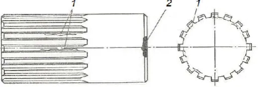
Fig. 2. Cylindrical splined samples 62 mm in diameter and 124 mm long made of different steels to be intensively quenched in spray system: 1 , cracks in splines; 2, cracks at the edge of a sample
Samples were made from differentf steel grades chemical composition of which is shown in Table 1. For each steel grade were made 6 samples. The samples were prepared by AutoKrAZ Co. for quenching them in lab condition in the frame of signed agreement. The goal of investigations was preventing any crack formation during intensive quenching, receiving maximal surface hardness, decreasing distortion of semi – axles, increasing their wear resistance, optimal cooling time correction and possibility of experimental simulation of quenching large steel parts in the lab codition. Removable size of sprayer 1 was manufactured depending on size and form of tested samples. For semi – axles samples inner diameter of sprayer was 120 mm and its hight was 150 mm. A manometer was located on the top of a sprayer to measure pressure in it during experiments. Powerful pump provided pressure in a sprayer up to 1.6 MPa (Kobasko, 1980). Experiments were made in condition when pressure in sprayer was between 0.9 MPa – 1.6 MPa. Some results of testing are presented in Table 2.
Table 1 Chemical composition of steels used for cylindrical samples simulating semi-axles of truck KrAZ to be tested in sprayer system shown in Fig. 1.
Steel C Si Mn Cr Ni Cu S P Notes
1040 GOST 1050 0.37 – 0.45 0.17 – 0.37 0.50 – 0.80 0.25 max 0.30 max - 0.04 max 0.035max 1050 GOST 1050 0.47 – 0.55 0.17 – 0.37 0.50 – 0.80 0.25 max 0.30 max - 0.045 max 0.04 max
47GT 0.44-0.51 0.10-0.25 0.95-1.25 0.25 0.25 0.30 < 0.04 < 0.04 Ti=0.06-0.012 4340 0.38 – 0.43 0.20 – 0.35 0.60 – 0.80 0.70-0.90 1.65 – 2.00 - 0.04 max 0.035max Mo = 0.20- 0.30 Note that average content of carbon C in steel 1040 and 4340 is 0.41 wt % while average content of carbon in steel 47GT is 0.475 wt. % and 0.51 wt % in steel 1050 (see Table 1) that is almost 25 % larger..
Table 2 Effect of intensive cooling time interruption on number of cracks and surface hardness after samples were quenched in sprayer system at a pressure 0.9 MPa.
Steel Cooling time, sec Number of cracks Hardness HRC on the top of spline Hardness HRC on the cylindrical surface
47GT 10 5 49 42
15 6 50 47
20 10 57 50
4340 10 0 49 47
15 0 52 49
25 0 57 57
[image:2.595.39.556.606.659.2] [image:2.595.65.530.719.797.2]Cylindrical splined samples (Fig. 2) were quenched in condition when Kondratjev number Kn = 1 and extremely intensive quenching was interrupted at 10, 15, 20, 25 and 40 seconds to see how cooling time affect crack formation and surface hardness due to self – tempering (Table 2). Carefully conducted experiments showed that after intensive quenching of splined cylindrical specimens made of 1040 and 4340 steel there were no cracks at all while specimens made of 47GT cracked in all experiments (see Table 2 and Table 3). It is explained by higher content of carbon in 1050 and 47GT steels. These carefully conducted experiments in 1980 raised an idea on the importance of developing optimal hardenability steel depending on sizes and configurations of products and method of its optimization. Also, it was shown that intensive quenching generates extra surface hardness (3 – 6 HRC units). On the top of spline hardness was below normal value due to tensile residual stresses (Kobasko, Morhuniuk, et.al., 1990) and hardness on cylindrical surface was above normal value due to compressive residual stresses on the surface of steel parts. It is very important to establish correlation between compressive residual stresses and extra surface hardness that can be used in the future for controlling the correctness of designed chemical composition of steel which depends on size and configuration of quenched product.
Table 3. Number of splines with cracks vs. pressure for 1050 and 47GT steels after 40 sec of intensive cooling
Steel Pressure in sprayer, MPa Number of cracks in 500 hrs Type of crack
1050 0.9 4 2
1.1 4 2
1.4 1 1
47GT 0.1 6 2
1.1 6 2
1.3 2 2
1.6 0 2
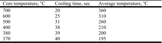
[image:3.595.169.428.415.485.2]Table 3 shows number of splines with cracks in each specimen. Maximum number of cracks appears when all splines of sample ar e cracked during intensive quenching. For example, number 4 in Table 3 means presence quenching cracks in four splines in cylindrical sample. It should be noted here that quench cracks were observed only in samples made of 47GT and 1050 steel and, as was already mentioned, no cracks were observed after intensive quenching 1040 and 4340 steel. Table 4 shows core temperature of cylindrical sample immediately after intensive cooling interruption and average temperature of self – tempering process which was calculated using well known method (Kobasko, Aronov, et. al., 2010).
Table 4. Core temperature versus time of cooling for cylindrical splined samples
Core temperature, oC Cooling time, sec Average temperature, oC
700 20 360
600 25 310
500 31 260
400 38 210
380 39 200
370 40 195
In spite of rather high temperature in the core of samples, cracks appeared in splines of cylindrical samples made of 1050 and 47GT steel. Due to very intensive quenching, splines were quenched through even after 10 sec of cooling. It means that probability of quench crack formation is higher in splined cylindrical samples made of 1050 and 47GT steel because specific volume of martensite is larger in 1050 and 47GT steel due to higher content of carbon (aproximately 25%). During through hardening core swells to larger extent in steel containing more cabon. Core swelling results in tensile stresses which can generate quench cracks. Using HART – TANDEM sofrware, authors (Kobasko, Morhuniuk, et. al., 1990) calculated surface splines tensile stresses which were formed during intensive quenching of culindrical samples shown in Fig. 2. These experiments and calculations whoved that semi – axles can be made from 1040 steel of GOST 1050 (see Table 1). Further explanations concerning this approach are provided below.
Analysis of experimental intensive quenching processes
To calculate water stream at the outlet of nozzle, a well known Eq. (1) was used which follows from the Bernoulli’s equations (Joseph, et. al., 1978):
2
2
v
P
(1)Where
P
is a pressure in sprayer,
is a coefficient depending on Re number and the nozzle configuration, ρ is liquid density,v
is outlet velocity. Coefficient
is used for flooded streams. Eq. (1) can be rewritten as:
P
v 2
Table 5. Outlet velocity of water from single nozzle versus pressure in sprayer shown in Fig. 1.
P, Mpa 0.2 0.4 0.6 0.8 0.9 1.0 1.4 1.5 1.6 v, m/s 20 28 35 40 42 45 53 55 56
Average HTCs for impingement jet cooling can be calculated with accuracy of ± 15 % using the following dimensionless correlation (Martin, 1990).
42 . 0 3 2 2
1
Re
Pr
K
K
u
N
(3)Where 05 . 0 6 1
6
.
0
/
1
H
D
f
K
;f
D
H
f
f
K
)
6
/
(
2
.
0
1
)
2
.
2
1
(
2
;
) ( 24
hexagon squareA
D
f
;D
is nozzle diameter;H
is a distance from the nozzle to the surface;A
is the area of the square or hexagon (see Fig. 7).f is a relative nozzle area in terms of geometric dimensions of nozzle and cooled surface arrangements (for example, this parameter is equal to 0.25·(D/r)2 for the single round nozzle).
Dimensionless numbers
K
1 andK
2 depend on the nozzle geometry and arrangement. Reynolds numberRe
depends on the outlet quenchant velocity and the number Pr characterizing physical properties of the quenchant. The above dimensionless correlation (3) is true for the following conditions: 2000Re100000; 0.004 f 0.04; 2 12D
H .
The task was to determine convective heat transfer coefficients for the sprayer described above in Fig. 1. First of all we will calculate all input parameters.
D
=0.002m;H
=0.01m;
0314 . 0 10 1 4 4 2 D f , 5
002 . 0 01 . 0 m m D
H ;
Pr
7
.
03
;Pr
0.42
2
.
268
; 19881/ 10 006 . 1 002 . 0 / 10
Re 6 2
s m m s
m ;
Re
3734
2
.Now calculate dimensionless complexes
K
1 andK
2:886
.
0
0314
.
0
6
.
0
5
1
05 . 0 6 1
K
; 0.110314 . 0 ) 6 5 ( 2 . 0 1 ) 0314 . 0 2 . 2 1 ( 0314 . 0 2 K .
It follows that
162
268
.
2
734
11
.
0
886
.
0
u
N
Whence
W
m
K
m
K
m
W
conv 2/
47790
002
.
0
/
597
.
0
162
.Some results of convective heat transfer coefficients (HTCs) calculations are presented in Table 6 depending on outlet velocity
v
[image:4.595.199.396.687.758.2]of water in sprayer and distance H to sample.
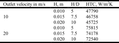
Table 6. Convective heat transfer coefficients (HTCs) developed in spray system depending on outlet velocity
v
of water in sprayer and distance H to sampleOutlet velocity in m/s H, m H/D HTC, W/m2K 0.010 5 47790 10 0.015 7.5 46758
0.020 10 45725 0.010 5 75815
20 0.015 7.5 74178 0.020 10 72540
Table 7. Time required for the surface of steel spheres of different sizes to cool to different temperatures when quenched from 875oC in 5% water solution of NaOH at 20oC agitated with 0.914 m/s (French, 1930)
Size, Inches, (mm) Time, sec
700oC 600oC 500oC 400oC 300oC 250oC 200oC 150oC 4.75” (120.6) 0.043 0.066 0.09 0.12 0.17 0.21 0.29 0.95 7.15” (181.6) 0.040 0.070 0.100 0.140 0.240 0.310 0.42 1.15 11.25” (285.8) 0.043 0.120 0.190 0.330 0.570 0.960 1.26 2.18
As seen from Table 7, surface temperature of spherical steel samples 120.6 mm in diameter drops from 875oC to 300oC only for 0.17 sec. This time of cooling for large spherical steel part 285.8 mm in diameter was 0.57 sec. So fast cooling is explained by absence of any film boiling and it can be explained by creation of double electrical layer between metal surface and boundary liquid layer which prevents film boiling development due to crucial electrical forces taking place during quenching in electrolytes. Proceedings from fulfilled calculations and experiments, one can claim that cylindrical specimens shown in Fig.2 were quenched in sprayer ideally providing for them condition Kn = 1.
Alloyed low hardenability steel and method of its designing
The powerful spray system shown in Fig. 1 can be successfully used for simulation hardening processes of large steel components in lab condition. The problem become very simple if boundary conditions are ideal when
Bi
and Kn = 1. In this case residual stresses in small model and big real steel part, like rotor or large roller, will be the same if are true Eqs.(4) (Kobasko, et. al., 1983, 1985):idem
R
a
2
;
idem
R
r
;idem
D
DI
opt a
. (4)
Here
DI
a is critical size for real steel components which has the same configuration as real steel part has;D
opt is size of real steel component which is manufactured from optimal hardenability steel (patented alloy low hardenability steel, UA Patent No. 114174, C2). The meaning of idem is “the same”.The proposed alloy low hardenability steel contains following alloy elements in wt.% (UA Patent No. 114174):
C: 0.30 - 1.20 Mn:
0.20 Si:
0.20 Cr:
0.50 Ni:
1.60 Mo:
0.25 Cu:
0.20 Al: 0.03 - 0.10 Ti: 0.05 - 0.12 V:
0.40 S:
0.035 P:
0.035 Fe: bal,It differs from early known low hardenability steels, which are shown in Table 8 and Table 9, by containing additionally molybdenum and elevated amount of nickel , up to 1.6 wt.%.
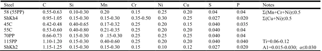
Table 8. Chemical composition of low hardenability (LH) steels used by authors (Shepelyakovskii and Ushakov, 1990; Ouchakov, 1998)
Steel C Si Mn Cr Ni Cu S P Notes
58 (55PP) 0.55-0.63 0.10-0.30 0.20 0.15 0.25 0.20 0.04 0.04 (Mn+Cr+Ni)0.5 ShKh4 0.95-1.05 0.15-0.30 0.15-0.30 0.35-0.50 0.30 0.25 0.027 0.020 (Cu+Ni)0.5 45С 0.42-0.48 0.40-0.65 0.17-0.32 0.25 0.20 0.15 0.040 0.035
55С 0.53-0.60 0.40-0.80 0.21-0.35 0.25 0.20 0.20 0.040 0.04 70PP 0.66-0.73 0.15-0.30 0 .15-0.30 0.25 0.25 0.25 0.040 0.04
115PP 1.10-1.20 0.15-0.30 0.40-0.60 0.25 0.20 0.20 0.040 0.040 Ti=0.06-0.12
ShKh2 1.15-1.25 0.15-0.30 0.15-0.30 0.15 0.10 0.12 0.027 0.020 A1=0.015-0.030; o0.030
[image:5.595.41.556.646.728.2]Table 9. Chemical composition of low hardenability (LH) steels according to RU Patent № 2158320
Елементи та DI
Chemical composition, wt %
62PP1 62PP2 62PP3 62PP4 62PP5 80PP
C Mn Si Cr Ni Cu Al Ti V S P 0.60-0.67 0.05-0.15 ≤0.05 ≤0.10 ≤0.10 ≤0.10 0.03-0.10 0.06-0.12 ≤0.4 ≤0.04 ≤0.035 0.60-0.67 ≤0.10 0.10-0.20 ≤0.10 ≤0.10 ≤0.10 0.03-0.10 0.06-0.12 ≤0.4 ≤0.04 ≤0.035 0.60-0.67 0.05-0.15 0.05-0.15 ≤0.10 ≤0.10 ≤0.10 0.03-0.10 0.06-0.12 ≤0.4 ≤0.04 ≤0.035 0.60-0.67 0.10-0.20 0.10-0.20 ≤0.10 ≤0.10 ≤0.10 0.03-0.10 0.06-0.12 ≤0.4 ≤0.04 ≤0.035 0.60-0.67 ≤0.06 ≤0.06 ≤0.06 ≤0.06 ≤0.06 0.03-0.10 0.06-0.12 0.2-0.3 ≤0.04 ≤0.035 0.78-0.085 ≤0.10 ≤0.05 ≤0.10 ≤0.10 ≤0.10 0.03-0.10 0.06-0.12 ≤0.04 ≤0.04 ≤0.035
DI. mm 8-13 8-12 8-13 11.5-15.5 8.5-9.5 10-12
Recently issued, a new patent on alloy LH steel (UA Patent № 114174, 2017) solves this problem making possibility use it for large steel components on the basis of developed method of its composing (Kobasko, 2017). The proposed method is based on fundamental correlation (5) which has a form:
095
.
0
35
.
0
opt aD
DI
. (5)
Where
DI
Form
f
DI
a
,
. (6)According to Grossmann (Grossmann, 1964) critical diameter DI for cylinder depends on chemical composition of steel, Eq. (7), and it can be calculated as:
...
4
.
25
f
Fef
Mnf
Sif
Crf
NiDI
(7)Hardenability factors
f
Fe and fx are provided by Table 10. For cylindrical formsDI
a
DI
. For more complicated forms ofsteel parts function (6) should be used which is calculated by computer program. This program can also find suitable chemical composition among already existing steel grades to fit for any form and size of product
D
opt to be optimized.Table 10. Hardenability factors
f
Fe and fx for steel depending on grain size and selected alloying elements (Totten et.al. , 1993)Content of carbon, wt.% fFedepending on grain size and content of carbon fxdepending on content of alloy elements, wt. %
No. 6 No.7 No.8 Mn Si Ni Cr Mo
0.10 0.1153 0.1065 0.0995 1.333 1.070 1.036 1.2160 1.30 0.20 0.1623 0.1509 0.1400 1.667 1.140 1.073 1.4320 1.60 0.30 0.1991 0.1849 0.1700 2.000 1.210 1.109 1.6480 1.90 0.35 0.2154 0.2000 0.1842 2.167 1.245 1.128 1.7560 2.05 0.40 0.2300 0.2130 0.1976 2.333 1.280 1.146 1.8640 2.20 0.45 0.2440 0.2259 0.2090 2.500 1.315 1.164 1.9720 2.35 0.50 0.2580 0.2380 0.2200 2.667 1.350 1.182 2.0800 2.50
To be sure that 1040 steel of GOST 1050 provides optimal hardened layer and is optimal for semi – axles 62 mm in diameter, let’s make calculation using correlation (5). Semi- axles for field testing were made from steel chemical composition of which was: 0.40C; 0.60 Mn; 0.30 Si; 0.10 Cr; 0.10 Ni; in wt. %. Knowing chemical composition of 1040 steel, one can calculate
DI
a forcylinder using data from Table 10. It is:
mm
DI
a
25
.
4
0
.
198
3
.
00
1
.
21
1
.
216
1
.
036
23
.
.And
02
.
0
35
.
0
37
.
0
62
23
opt aD
DI
[image:6.595.64.532.522.613.2]As a result, fatigue tests of KrAZ truck semi – axles were excellent (see Table 11).
Table 11. Fatigue tests of KrAZ truck semi – axles (Kobasko. 1980)
Quenching method Steel grade Numbers of cycles to fracture Notes
Oil AISI/SAE 4340 3.8 – 4..6 105 Semi – axles were destroyed Intensive water spray cooling AISI/SAE 1040 3.0 – 3..5 106 No fracture observed
It turned out that conventional 1040 steel fits thickness of semi – axle 62 mm in diameter to be an optimal composition for this specific size. Since alloy low hardenability steel is designed for medium and large steel parts, it is extremely important to develop a method of experimental and computer simulation quenching processes of large steel components in lab condition because experiments with real large steel components like rotors are very expensive. This problem is discussed below. .
Computer simulation of large steel parts quenching processes
[image:7.595.156.446.348.499.2]Assume that there is a roller 800 mm in diameter and 1400 mm long which should be manufactured from the alloy low hardenability steel. Its configuration is similar to model shown in Fig. 3, however, it is 10 times larger. Real large roller will be quenched intensively in condition when Kn = 1 in water tank with a moving flooded sprayer (Kobasko, 2013). There is a need to investigate stress and phase distribution in large roller during its intensive quenching and evaluate safe factor to see whether quench cracks could appear during hardening. A small model of large roller is shown in Fig. 3 and is manufactured from the AISI/SAE 52100 steel which satisfies approximately fundamental Eq. (5). The model shown in Fig. 3 can be quenched in removable sprayer 1 of Fig. 1 in condition Kn = 1 and investigated by FEM (finite element method) computer calculations if CCT (continuous curves transformation) diagram (Fig. 4) and mechanical properties of material vs. temperature are known. Such calculations and analysis related to small model shown in Fig. 3 are provided below.
Fig. 3. Drawing of a roller (model) with the maximal diameter 80 mm and 140 mm long to simulate hardening processes in 10 times larger roller for which
DI
a/
D
opt is the same [image:7.595.170.419.558.773.2]Mechanical properties of steel shown in Fig. 4 vs. temperature can be find in literature (Kobasko, Morhuniuk, et. al., 2017).
Fig. 5 Temperature field in a small roller in K at the moment of time70 sec when quenched in condition Kn = 1.
Fig. 6 supports an idea on preventing quench cracking when quenching is very intensive and uniform. Combining this important fact with the optimized chemical composition of steel, one can guarantee absence of crack formation in large steel components like rotors and big rollers. More information on safe factor k
x,y,
one can find in Ref. (Pisarenko and Lebedev, 1976; Morhuniuk, 1982).Fig. 7 Micro – structure distribution in a small roller at the moment of time70 sec when quenched in condition Kn = 1: 3 is bainite, 4 is pearlite, 5 is martensite.
As seen from Fig. 6 and Fig. 7, the lowest safe factor k and the boundary between bainitic and martyensitic structure have the sane location. It means that probability of crack formation is high along the boundary bainitic – martensitic structure. Results of computer calculations, presented in Fig. 8, support the main rule according to which on the surface of through hardened steel parts neutral or tensile stresses during quenching are formed. In our case, in through hardened cylindrical section of the roller surface hoop stresses were 80 MPa (swee Fig. 8). Surface compressive hoop stresses in cylinder with the section of 180 mm were more than – 1000 MPA (see Fig. 8). A ratio of hardened layer (100% martensite) to large diameter of the is equal to 0.27. Core of the roller has pearlitic structure and bainitic structure is located between pearlite and martensite.
[image:10.595.66.538.461.763.2]Fig. 9. Surface hoop stresses in the intersection of different diameters of small roller in MPa at the moment of time70 sec when quenched in condition Kn = 1.
As follows from Fig. 9, at the intrersectio of different diameters of roller, high surface compressive hoop stresses are formed . It is due to formation of martensitic shell which is smoothly distributed around the surface of a roller (see Fig. 10). In area pont 7, where small diameter of the roller appraches the large diameter, compressive hoop stresses are: - 480 MPa, - 920 MPa, -1000 MPa (see Fig. 9). It is clear to everybody that such comprerssive stress distribution cannot generate quench crack formation. In point 7 save factor k is highest and is equal to 1.9. Quench cracks are formed when k
x,y.
1(Pisarenko – Lebedev, 1976). Fig. 10 shows the martensitic shell formed around the roller at the moment of intensive cooling 5 sec (a) and 10 sec (b). [image:11.595.74.522.145.397.2]Fig. 11 Temperature field in K in small roller at the beginning of cooling in condition Kn = 1 : a), after 5 sec; b), after 10 sec.
Fig. 11 presents the temperature field in Kelvin centigrade (K) in the small roller at the beginning of cooling in condition Kn = 1 atn the moment of time 5 sec (a) and 10 sec (b). At the beginning of cooling the martensitic shell is covered hot core of the roller consisting of plastic austenite. No quench cracks in such condition are possible. Thus, computer simulation shows that no quench crack at all when quenching rollers, made of optimal hardenability steel, in ideal condition provided by flooded movable sprayers
(Kobasko, 2013). Similar stress and phase distribution will be in 10 times larger roller if 2
R a,
R
r
, and
opt a
D
DI are the same.
DISCUSSION
There are two companies dealing with intensive quenching processes to suggest their developments to interested customers: IQ Technologies Inc. (IQT) and Intensive Technologies Ltd. (ITL). IQ Technologies Inc is an engineering consulting firm founded in 1999 in Akron, Ohio, USA. IQ Technologies Inc is dedicated to enhancing the performance, environmental soundness, cost effectiveness, and safety of heat-treating processes. The prime its mission is to commercialize intensive quenching processes for steel parts in US and abroad and to provide intelligent solution of wide range of heat-treating problems. It is committed to IntensiQuench® process and equipment engineering excellence, and it is working as a team consisting of DANTE Solution Inc., Air Flow Science Corporation, AFC-Holcroft, Ajax TOCCO Magnethermic, etc. The consulting company Intensive Technologies Ltd (ITL) was founded in 2000 in Kyiv, Ukraine and its prime mission is development of new intensive quenching processes, designing appropriate software for governing of developed new technologies. It is cooperating with leading experts from National Academy of Sciences of Ukraine and National Metallurgical Academy of Ukraine. Combined activity of both companies will bring a great benefit to heat treating industry because IQT mainly focuses on designing and manufacturing equipment for IQ processes while ITL focuses on academic painstaking experimental and analytical investigations to govern correctly technological processes. As a good example for illustrating a great sense of mutual cooperation is an alloy low hardenability steel, discussed in this paper, which will be used sooner or later worldwide for IQ – 3 processes including large steel parts like rotors and others (UA Patent No. 109577, 2015). Accurate computer simulation can be done for them using contemporary computer codes (Dowling, Pattok, Ferguson et.al. 1996; Inoue and Arimoto, 1997; Ferguson, et. al., 2002, 2007).
Conclusion
A method for composing alloyed low hardenability steel depending on size and configuration of machine component is proposed which is based on regular condition theory and theory of similarity.
A possibility of simulation process of intensive quenching very large components made of alloyed low hardenability steel in a lab experimental condition is realistic if Fourier number, dimensionless coordinates, and DIa/D are the same.
Intensively quenched alloy low hardenability steel provides high surface compressive residual stresses which accedes 1000 MPa and relatively low tensile stresses at the core of steel parts.
High surface compressive residual stresses are the reason for high surface hardness which can be HRC 65 for AISI 1040 steel.
Different hardness on cylindrical and splined surfaces is explained by differences in residual surface stresses.
Optimal hardenability steel for specific steel part can be designed as a new one or chosen from already existing grades using fundamental correlation for steel chemical composition optimization.
REFERENCES
Dowling, W., T. Pattok, B. L. Ferguson D., Shick, Y. Gu, and M. Howes, 1996. Development of a Carburizing and Quenching Simulation Tool, The 2nd International Conference on Quenching and Control of Distortion, ASM International, Cleveland, OH.
Ferguson, B. L., A. M. Freborg, and Z. Li, 2007. Improving Gear Performance by Intensive Quenching, Proceedings of the 24th ASM Heat Treating Conference, pp. 156–162.
Ferguson, B. L., A. M. Freborg, G. J. Petrus, and M. L. Collabresi, 2002. Predicting the Heat Treat Response of a Carburized Helical Gear, Gear Technology, pp. 20–25.
French, H. J., 1930. The Quenching of Steels, Cleveland, Ohio, USA: American Society for Steel Treating, 177. Grossmann, M. A., 1964. Principles of Heat Treatment. Ohio: American Society for Metals, 302 pages.
Inoue, T., and K. Arimoto, 1997. Development and Implementation of CAE System “Hearts” for Heat Treatment Simulation Based on Metallo-thermo-mechanics, Journal of Materials Engineering and Performance, Vol. 16, No. 1, pp. 51–60.
Joseph, A., Pomeranz, K., Prince, J., Sacher, D., 1978. Physics for Engineering Technology, Second Edition, John Wiley & Sons, NY, 629 pages.
Kobasko, N. I., and W. S. Morhuniuk, 1983. Study of thermal and stress-strain state at heat treatment of machine parts, Znanie, Kyiv, 18 pages.
Kobasko, N. I., and W. S. Morhuniuk, 1985. Numerical Study of Phase Changes, Current and Residual Stresses at Quenching Parts of Complex Configuration, Proceedings of the 4th International Congress of Heat Treatment Materials, Berlin, Vol. 1, pp. 465–486.
Kobasko, N. I., W. S. Morhuniuk, and A. P. Morganyuk, 1990. Hardening of Complex Configuration Bodies by Intensive Cooling, Proceedings of the 7th International Congress on Heat Treatment of Materials, December 11–14, 1990, Moscow, Vol. 2, pp. 232–239.
Kobasko, N., Aronov, M., Powell, J., Totten, G., 2010. Intensive Quenching Systems: Engineering and Design. ASTM International, 242. doi: 10.1520/mnl64-eb
Kobasko, N.,, 2005. Quench Process Optimization for Receiving Super Strong Materials, Proceedings of the 5th WSEAS Int. Conf. on SIMULATION, MODELING AND OPTIMIZATION, Corfu, Greece, August 17-19, 2005, pp. 365-372.
Kobasko, N.I., (1980). Steel Quenching in Liquid Media under Pressure, Naukova Dumka, Kyiv, 206 pages.
Kobasko, N.I., 2017. A method for optimizing chemical composition of steels to reduce radically their alloy elements and increase service life of machine components, EUREKA: Physics and Engineering, Number 1, pp. 3 – 12. DOI: 10.21303/2461-4262.2016.00253.
Kobasko, N.I., Dobryvechir, V.V., Morhuniuk, W.S., 2017. Contemporary methods for cooling time calculation and hardening processes analyzing, International Journal of Current Research 9, (11), pp. 60367-60376
Martin, H., Impinging Jets, Hemisphere Handbook of Heat Exchanger Design, G. F. Hewitt, Coordinating Ed., Hemisphere, New York.1990.
Morhuniuk, W.S., 1982. Steel Articles During Hardening, Strength of Materials, Vol. 14, 1982, pp. 807–814, translated from Problemy Prochnosti, No. 6, pp. 80–85.
Ouchakov Boris K., Shepelyakovskii Konstantin Z., 1998. New Steels and Methods for Induction Hardening of Bearing Rings and Rollers, Bearing Steels: Into the 21st Century, ASTM STP 1327; Hoo, J.J.C., Editor, American Society for Testing of Materials, pp. 307 - 320
Patent RU № 2158320, Filed on Nov. 29, 1999, File number No. 99125102.
Patent UA No. 109577 UA., 2015, A method of hardening large steel products of complicated shapes and apparatus for its performing. MPK: C21D 1/18, C21D 1/667, C21D 1/78, C21D 1/62, C21D 9/28. No. 201313211; declared 13.11.2013; published: 10.09.2015, Bul. No. 17.
Patent UA 114174, C2, Alloyed Low Hardenability Steel and Method of its Designing, Filed on Sep.23, 2013, File number: a 2013 11311, Published on June 25, 2016 in Bulletin No. 12, Legal day is May 10, 2017 .
Pisarenko, G.S., Lebedev, A.A., 1976. Deformation and Strength for Complex Stress State, Naukova Dumka, Kyiv (In Russian). Shepelyakovskii, K.Z., Ushakov, B.K., Induction Surface Hardening – Progressive Technology of XX and XXI Centuries,
Proceedings of the 7th International Congress on Heat Treatment and Technology of Surface Coatings, Vol. 2, Moscow, Russia, 11- 14 Dec., 1990, pp. 33 – 40.
Shepelyakovswkii, K.Z., Bezmenov, F.V., New Induction Hardening Technology, Advanced Materials & Processes, October, 1998, pp. 225 – 227.