138 |
P a g e
NON LINEAR SIMULATION OF ENGINE BRACKET
UNDER DYNAMIC LOADING
Harish Harsurkar
1, Sahebagouda Sanganagoudar
2, Anand Matikalli
3 1P G Student,
3Assistant Professor, Department of Mechanical Engineering,
Maratha Mandal College of Engineering Belagavi, (India)
2
Assistant Professor, Department of Mechanical Engineering,VSM Institute of Technology
Nipani, (India)
ABSTRACT
The automotive engine mounting systems are very important due to different aspects of vehicle performance. Early in improvement the building of the engine mounting system should be rapidly checked and precisely analyzed, without sample of a vehicle authorization. Engine bracket has been designed as a framework to support engine. Vibration and fatigue of engine bracket has been continuously a concern which may lead to structural failure if the resulting vibration and stresses are severe and excessive. It is a significant study which requires in-depth investigation to understand the structural characteristics and its dynamic behavior. This paper presents and focuses on some Finite Element (FE) analysis of a typical engine bracket of a car will be carried out and natural frequency will be determined
Keywords: Modal FEA; Engine Mounting Bracket
I. INTRODUCTION
Engine is one of the most important components of a road vehicle such as car. High performance sports car has their engine supported by bracket. It plays an important role in improving the comfort & work environment of a car. The improvement of engine bracket system has been the subject of intense interest for many years. It is necessary to design proper engine bracket for a car.
The vehicle engine mounting system, generally, consists of an engine (vibration source) and several mounts connected to the vehicle structure. The modern engine mounting systems have been successfully used to isolate the driver and passenger from both noise and vibration generated by the engine. However, there is still a need to improve the performance of engine mounting systems for the following two reasons:
The modern car designs have a trend for lighter car bodies and more power-intensive engines. Such a
weight reduction and increased power requirements often have adverse effects on vibratory behavior, greatly increasing the vibration and noise level.
The requirements of vibration and noise level isolation for passenger cars.
139 |
P a g e
II. LITERATURE SURVEY
Enormous literature is available regarding the simulation of engine mounting bracket in crash analysis, critical loading conditions in the research papers and conference proceedings. Out of these a few noteworthy works are squeezed and briefly presented here.
Mahendra Gaikwad [1] The automotive engine mounting systems are very important due to different aspects of vehicle performance. Early in improvement the building of the engine mounting system should be rapidly checked and precisely analyzed, without sample of a vehicle authorization. Engine bracket has been designed as a framework to support engine. Vibration and fatigue of engine bracket has been continuously a concern which may lead to structural failure if the resulting vibration and stresses are severe and excessive. Vibration plays a critical role in Engine components, especially in the supporting bracket. Gray Cast Iron is essentially a brittle material and this is evident in the results that the low natural frequency will prove as a hindrance in vibration characteristic of the bracket. In terms of analysis, Al alloy and Mg alloy are showing almost same value of natural frequency and indicate that any one of them would be a better choice than Gray Cast Iron.
A.S. Sathawane [2] An engine mount is a connecting link between vehicle chassis and engine. The engine excitation forces arising from firing pulse and unbalanced forces are widely considered among the main vibration sources for the road vehicles. The objectives of this work are to study the frequency-dependent stiffness of engine rubber mount. The ideal engine mount system should reduce engine vibration caused by engine vibratory force in engine and prevent engine bounce from shock excitation.
AbdolvahabAgharkakli [3] This study summarizes the methodology to find the linear mount characteristics with the help of mathematical models and comparison of these results with results from MATLAB simulations. The mounts are treated at the component level, and mathematical models for the same are evaluated to get the required characteristics. The mounts are modelled as spring and damper system subjected to impact loading that occurs during crash events. The approximation of input pulse has been described mathematically, which then serves to find the characteristics of the mounts. The change in the characteristics of mounts with the change in the velocity of impact has also been studied.
Dr.C.Udaya Kiran [4]This paper describes the design of an engine mounting bracket by the application of Altair Optistruct, Compared with original design of mounting bracket, using three commonly preferred materials for manufacturing the mounting bracket as Aluminium alloy, Aluminium silicon carbide, and grey cast iron, the mass on the final design is reduced about 50% without compromising its strength and functionality. It is strong enough in fatigue and strength with improved functionality.
Prof. V.K. Kurkute [5] The Engine is one of the most important components of a road vehicle such as car. High performance sports car has their engine supported by bracket. It plays an important role in improving the comfort & work environment of a car.. Fatigue of engine bracket has been continuously a concern which may lead to structural failure if the resulting stresses are severe and excessive. Prolonged exposure to whole-body stresses in the working environment may lead to fatigue and in some cases it damages the car. Objective of the project is to select the light weight material & reduce the weight of the bracket.
140 |
P a g e
of 87 kilograms. The strategy of increasing use of light alloy content in vehicle has proven to be a successful method of achieving fuel efficiency and environmental concerns.. The strong emphasis on the cost has demanded the component manufacturers to improve the performance of their materials and to find the methods to deliver these materials at reduced cost.David Looper [6] Over the past couple decades; oilfield service rolling equipment has significantly increased in weight. The primary reason for this is due to emissions regulations, which require larger/heavier engines, larger cooling systems, emissions after treatment systems in some cases, etc. Larger engines give rise to more vibrations and shock loads leading to failure of electronics and control systems. If the vibrating frequency of the engine matches the system frequency, high resonance is seen on structural parts and mounts. One such existing system comprised of wire rope mounts used for mounting computers was designed about 12 years ago when the ACE (Automated Control Equipment) control system was first introduced to fracturing equipment. This included the use of an industrial grade computer to control the system operation. The original computer had a smaller lighter enclosure
III. SIMULATION AND RESULTS
Simulation is the processes of product validation were the product is tested with defined boundary conditions and assumed parameters.
3.1 Boundary Conditions
Objective:Evaluating the robustness of engine mounting bracket w.r.t to below boundary condition.
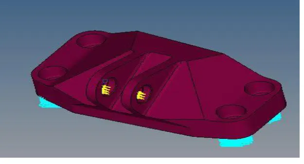
Figure 3.1: Two Product Clamping Without X-Brace Model Setup
3.2 Model Setup
141 |
P a g e
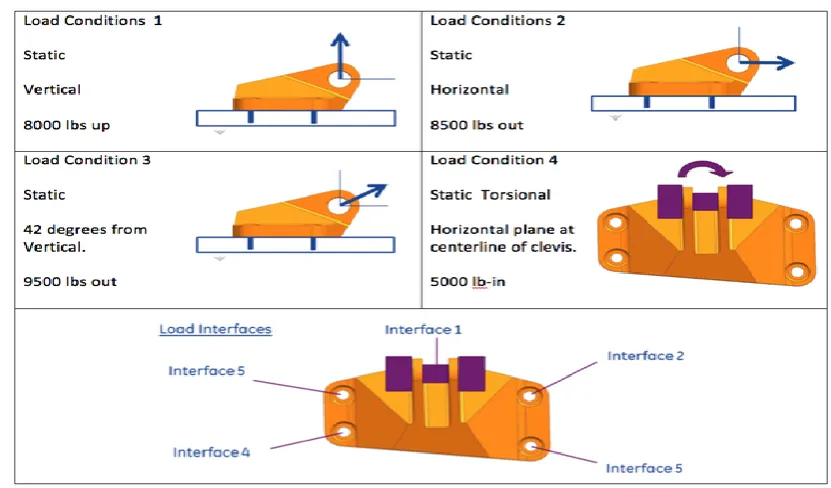
Figure 3.2: Loading Conditions on Engine Mounting Bracket
In the model setup, the four base holes are constrained in all 6 DOFS were the and evaluated in only one loading condition which is as follows
1. Load of 8000 lbf (35,587 N) Vertical.
2. Load of 8500 lbf (37,800 N) Horizontal.
3. Load of 9500 lbf (41,200 N) 42 degree from Vertical. 4. Static Torsion of 5000 lbf.
3.3 Counter Plots
Simulation is carried out for loading condition 1 i.e., load of 8000 lbf (35,587 N) Vertical. 3.3.1 Material – Gray Cast Iron
Stress and Displacement Plot (GE Base line Model)
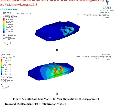
From the figure 3.3, we observe the maximum Von Mises stress of 1076.3 Mpa and displacement of 6.08 mm.
142 |
P a g e
(b)
Figure 3.3: GE Base Line Model: (a) Von Misses Stress (b) Displacement
Stress and Displacement Plot ( Optimization Model )
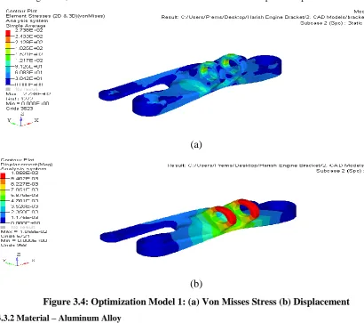
From the figure 3.4, we observe the maximum Von Mises stress of 273.8 Mpa and displacement of 10.5 mm.
(a)
(b)
Figure 3.4: Optimization Model 1: (a) Von Misses Stress (b) Displacement
3.3.2 Material – Aluminum Alloy
Stress and Displacement Plot (GE Base line Model)
143 |
P a g e
(a)
(b)
Figure 3.5: GE Base Line Model: (a) Von Misses Stress (b) Displacement
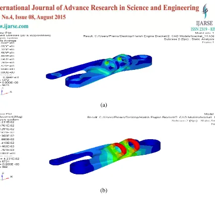
Stress and Displacement Plot ( Optimization Model )
From the figure 3.6, we observe the maximum Von Mises stress of 102.7 Mpa and displacement of 16.9 mm.
144 |
P a g e
(b)
Figure 3.6: Optimization Model 1: (a) Von Misses Stress (b) Displacement
3.3.3 Material – Magnesium Alloy
Stress and Displacement Plot (GE Base line Model)
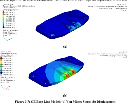
From the figure 3.7, we observe the maximum Von Mises stress of 215.1 Mpa and displacement of 30.4 mm.
(a)
(b)
Figure 3.7: GE Base Line Model: (a) Von Misses Stress (b) Displacement
Stress and Displacement Plot ( Optimization Model )
145 |
P a g e
(a)
(b)
Figure 3.8: Optimization Model 1: (a) Von Misses Stress (b) Displacement
3.4 Summary of Results and Discussion
In this section we will discuss and compare the results such of contour plots, individual parts, stress and displacements obtained from the statically loading conditions.
The table 3.1 shows the summary of contour plots of engine mounting bracket for different materials. In this table stress and displacement results of different materials engine mounting bracket are compared and risk factor involved in it is observed.
Table 3.1: Summary of Contour Plots
Model
Materials
Displacement
(mm)
Stress
(Mpa)
Weight
Risk
Base Line
Model
Gray C I
6.08
1076.3
2.5 kg
HIGH RISK
Al Alloy
15.2
537.9
1.9 kg
NO RISK
Mg Alloy
30.4
215.1
1.8 kg
NO RISK
Modified /
Optimized
Model
Gray C I
10.5
273.8
1.9 kg
HIGH RISK
Al Alloy
16.9
102.7
1.4 kg
NO RISK
146 |
P a g e
Following observations were made.1) For simulation without base line model with gray cast iron material have high stress values due to its brittleness in nature it will fail in loading condition.
2) Al alloy & Mg alloy of baseline model are having high stress values but the displacement in them is too low.
3) Modified / Optimized model with gray cat iron material have high stress values which is beyond its yield limit it will fail in loading condition.
4) In the simulation it is proved that the new design i.e., modified / optimized model with Al alloy & Mg alloy are efficient in statically loading condition.
5) In which looking the stress and displacement factors with low natural frequency Al alloy with base line & optimized model engine mount plays a safe role in load caring at statically conditions.
6) For verification with crash analysis the two models i.e., ( Al Alloy Baseline & Optimized model ) are considered.
7) 73 % of weight reduction is absorbed in Al alloy engine mounting bracket as compared to base line model.
IV.CONCLUSION AND RECOMMENDATIONS
In this project work, static & crash analysis of engine mounting bracket is carried out. Simulation is carried out in two cases that are with baseline model and with optimized model of engine mounting bracket. Here Altair Hypermesh v11 tool is used for meshing the complete model and passed the quality criteria’s such as Quality Index, Skewness, warpage, Jacobian etc. The FE model is successfully analyzed using LS Dyna software and material; connections of the model are created as per current industry practices so as to co-relate it with practical test. After completing the analysis contour plots and energy plots of both the simulations are compared.
As per the standard loading condition engine mounting bracket was evaluated in static analysis & the standard force of 14.23 KN required as per front crash analysis was applied in engine mounting brackets the results of simulation were taken at 14.23 KN load . By comparing the results of simulation static and crash analysis with experimental test it can be concluded that.
1. High stress and displacement are seen in base line model w.r.t Gray cast iron, Al alloys & Mg alloys materials which are crossing its yield strength.
2. Modification and Optimization of baseline model with increased web thickness and front side base frame. 3. There is considerable reduction in stresses and displacement of optimized model w.r.t Gray cast iron, Al
alloys & Mg alloy materials.
4. New optimized design of engine mounting brackets with gray cast iron has high stresses and but low displacement to its brittle in nature so it will be fail in loading conditions.
5. Modified optimization model & Base line model of Al alloy material is considered for crash analysis impact as stress and displacement in both models is comparatively low.
6. Applying the front impact collision standards on two models was seen displacements were 31.77 mm in base line model and 10.59 mm in optimized model.
147 |
P a g e
8. 73 % of weight reduction is absorbed in Al alloy engine mounting bracket as compared to base line model. By these conclusions we can say that the modified & optimized model of engine mounting bracket of material Al alloys is safe for engine mounting loading condition and would be used in future.The following are the future recommendations which can improve the optimized model of Al alloy engine mounting brackets.
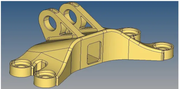
1. Referring to the below figure the optimized or the below model of engine bracket must be evaluated which will play a vital role in weight reduction factor.
Fig 4.1: Recommended Engine Mounting Bracket
REFERENCES
[1]. Umesh S. Ghorpade, D. S. Chavan, Vinay Patil & Mahendra Gaikwad “Finite Element Analysis And Natural Frequency Optimization Of Engine Bracket” International Journal Of Mechanical And Industrial
Engineering (Ijmie) Issn No. 2231 –6477, Vol-2, Iss-3, 2012.
[2]. A. S. Sathawane, A. V. Patil “Analytical Study Of Engine Mount To Suit The Damping Requirements Of Engine” International Journal Of Latest Trends In Engineering And Technology Issn: 2278-621 (Ijltet),
Vol. 3 Issue 3 January 2014.
[3]. AbdolvahabAgharkakli, DigvijayPradipWagh, “Linear Characterization Of Engine Mount And Body Mount For Crash Analysis” International Journal Of Engineering And Advanced Technology (Ijeat) Issn: 2249 – 8958, Volume-3, Issue-2, December 2013.
[4]. A.PrasadBabu, Y.Vijaya Kumar, Dr.C.Udaya Kiran, “Topology Optimization In Design Of Engine Mounting Bracket” International Conference On Emerging Trends In Mechanical Engineering Iceme-2014 , Isbn: 978-93-82163-09-1 .Volume- 1, 24th, 25th February 2014.
[5]. Mr. PramodWalunje, Prof. V.K. Kurkute “Optimization Of Engine Mounting Bracket Using Fea” Paripex - Indian Journal Of Research, Issn - 2250-1991, Volume : 2 | Issue : 12 | Dec 2013.
[6]. Vishwajit M. Ghatge, David Looper “Fem And Experimental Modal Analysis Of Computer Mount” International Journal Of Emerging Technology And Advanced Engineering, Vol 73, February 2014, Pp. 112-116.
148 |
P a g e
[8]. A.S.Adkine1, V.S.Kathavate2, G.P.Overikar1, S.N.Doijode, “Static Behaviour Of Engine MountingBracket” International Advanced Research Journal In Science, Engineering And Technology, Issn (Online) 2393-8021,Issn (Print) 2394-1588, Vol. 2, Issue 4, April 2015.
[9]. Cao, C. And Medepalli, S., "Statistical Relationship Between Corner Weight And Spindle Load," Sae Technical Paper 2007-01-1346, 2007, Doi:10.4271/2007-01-1346.