ISSN(Online): 2319-8753 ISSN (Print): 2347-6710
I
nternational
J
ournal of
I
nnovative
R
esearch in
S
cience,
E
ngineering and
T
echnology
(A High Impact Factor, Monthly, Peer Reviewed Journal) Visit: www.ijirset.com
Vol. 7, Issue 3, March 2018
Fault Location with Using Window Least
Square Method
Dinesh.K1, Dinakaran.K.P2, Saisuhas.R3, Abishaiksivakumar.S4, Vinoth.P5
Assistant Professor, Department of E.E.E, Panimalar Institute of Technology, Chennai, India1,2
UG Scholars, Department of E.E.E, Panimalar Institute of Technology, Chennai, India3-5
ABSTRACT: DC fault current is contributed by various distributed energy resources in dc distribution systems. The tightly coupled dc distribution systems have relatively low line impedance values. The fault current increases fast because of the low impedance. Some converters in dc distribution systems include fault current limiting function. The controlled fault currents at different locations are very close. Thus, it is important to design a reliable and fast fault detection and location method for dc distribution systems. This paper proposes a novel local measurement-based fault location algorithm for tightly coupled dc distribution systems. The proposed fault location algorithm can estimate the equivalent inductance between a protective device and a fault in less than 1 ms.The performance of the developed protection algorithm was validated by numerical simulation and hardware tests.
KEYWORDS: Impedance, simulation, novel.
I. INTRODUCTION
Fig 1.
II. PROBLEM STATEMENT
The one-line-diagram of a dc distribution system is shown in Fig. 1. The system includes a specific ac/dc uninterruptible power supply (UPS), lines, loads, and protective devices (such as circuit breakers). Even though the dc/dc converter in this algorithm has been validated in a hardware- in-the-loop simulation environment [14]. The main contribution of this work is the validation of the novel local measurement- based fault location algorithm in a hardware testbed. The technical work has been previously presented in [15].UPS has a fault current limiter to limit the averaged current from up- stream sources to a predefined low current value, the discharging current of the UPS output capacitor is uncontrollable. The capacitor discharging current is the predominant fault current and is high enough to damage devices or equipment. Due to low impedance values in tightly coupled systems, the fault current can reach its peak value within 1 ms. with this quickly developed dc fault current, it is vital for protective devices to interrupt the fault current timely to avoid any damage to equipment and to minimize the impact of the fault. The total dc protection response time t can be estimated by (1). It consists of fault detection time t, fault location time communication time and device turning- off time t
t = tdetection + location + comm. + tprot.
To avoid the communication delay, local measurement-based protection methods are preferred. Fast fault detection and location becomes an essential requirement for fast protective devices. Each protective device measures local electrical variables. A local controller is embedded with each protective device to implement the fast fault detection and location algorithm. The algorithm differentiates internal faults and external faults for each protection zone. The protection controller sends tripping commands to the protective device. The estimated distance to fault will be used to achieve protection coordination without any communication between protective devices. This method does not require any communication to achieve coordination, and thus, the fault location and isolation time can be minimized. The pro- posed fault location
III. NOVEL DC FAULT LICATION METHOD
ISSN(Online): 2319-8753 ISSN (Print): 2347-6710
I
nternational
J
ournal of
I
nnovative
R
esearch in
S
cience,
E
ngineering and
T
echnology
(A High Impact Factor, Monthly, Peer Reviewed Journal) Visit: www.ijirset.com
Vol. 7, Issue 3, March 2018
normally are uncontrolled for a few milliseconds before limited to a constant value. The transient voltage, current, and
di/dtsignals are measured at each protective device. The measured signals are used to
Fig.2 Equivalent inductances in levels 1–3.
Fig.3 Equivalent circuit used in the equivalent inductance estimation.
Estimate the equivalent fault inductance between the local protective device and the fault. The inductance distribution in levels 1–3 of the system is illustrated in Fig. 2. L1, L2, and L3 represent the equivalent inductances of levels 1–3. If
the estimated inductance is less than the known line inductance, the fault is considered as an internal fault. The local protective device will open to isolate the faulted segments and the healthy part will go back to normal operation.To estimate the equivalent inductance between a protective device and a fault, an equivalent electric circuit is used. as shown in Fig. 3. Circuit parameters L and R represent the equivalent inductance and resistance between the protective device and the fault. RFis the fault resistance. The state-space equation of the circuit is expressed as
(
F)
di
V
L
R
R i
dt
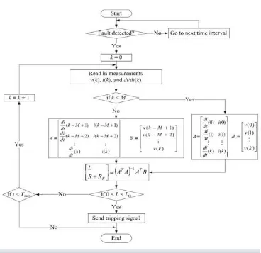
The voltage, current, and di/dt are sampled at various time steps. (R + RF) and L are estimated from the data samples. At multiple time instants using the least-squares method. The relationship of the sampled data is shown in Fig.6 Where,
Fig .4 Flowchart of the proposed fault location algorithm
flowchart is shown in Fig. 4. Once a fault is detected by over current and/or under voltage, the fault location routine is activated.
ISSN(Online): 2319-8753 ISSN (Print): 2347-6710
I
nternational
J
ournal of
I
nnovative
R
esearch in
S
cience,
E
ngineering and
T
echnology
(A High Impact Factor, Monthly, Peer Reviewed Journal) Visit: www.ijirset.com
Vol. 7, Issue 3, March 2018
Fig.6 Hardware setup
The measured voltage, current, and di/dt signals at different time instants are used to estimate the equivalent inductance. If data samples are less than M (M is the size of the moving window of the least square method), all the data are used in the inductance samples are less than M (M is the size of the moving window of the least square method), all the data are used in the inductance.
IV.NUMERICAL SIMULATION
In this section, numerical simulation is used to validate the proposed fault location algorithm. A low voltage dc (LVDC) distribution system is simulated in MATLAB/Sim Power System with a step size of 5 µs. The simulated LVDC system is shown in Fig. 5. The UPS rating is 100 kW and the output voltage is 380 V dc. The converter in the UPS has a fault current limiter. Once
level 2 feeder supplies power to four level 3 feeders and each level 3 feeder supplies power to eight constant resistive loads. The equivalent inductance of level 3 feeder is 4.8 µH. The inductance from level 4 breaker to load is 0.432
µH.the fault.Fault 3 is at the downstream of a level 4 breaker. The estimated inductance at the level 3 breaker is shown in Fig. 8.In order to differentiate the levels 3 and 4 faults, a zonal boundary inductor with 2.5 µH is inserted right before each level 4 breaker. Due to the inserted inductor, the estimated inductance at the level 3.and 4 faults, a zonal boundary inductor with 2.5 µH is inserted right before each level 4 breaker. Due to the inserted inductor, the estimated inductance at the level 3.
Fig.8Input signal voltage
ISSN(Online): 2319-8753 ISSN (Print): 2347-6710
I
nternational
J
ournal of
I
nnovative
R
esearch in
S
cience,
E
ngineering and
T
echnology
(A High Impact Factor, Monthly, Peer Reviewed Journal) Visit: www.ijirset.com
Vol. 7, Issue 3, March 2018
Fig.10 Output signalvoltage
Breaker is above the upper threshold of level 3 and within the tripping zone of level 4, so the level 3 breaker keeps closed and the level 4 breaker is selected to isolate the fault.The numerical simulation results verify that the fault location algorithm can accurately locate faults in the dc distribution system. The fault is detected and located within 1 ms.the inserted zonal boundary inductors provide sufficient discriminations at special conditions and ensure the selectivity of the proposed inductance-based fault location method.
V.HARDWAREVALIDATION
In this section, the hardware validation of the developed inductance-based dc protection scheme is discussed. The di- agram of the scaled-down hardware testing circuit is shown in Fig. 9. The scaled-down hardware test system is illustrated
Fig.11 HARDWARE KIT
capacitor and system equivalent inductors are included in the hardware testing circuit. The capacitor is charged to 12 V dc before each the implementation of the developed protection algorithm on the board is shown in Fig. 11. One PRU sequentially reads in data from the analog input channels. The data sampling period is 7 µs. The voltage, current, and
di/dtare read in sequentially, so the total time to get all samples at one data point is 21 µs. The data are then stored in the processor memory. Once a fault is detected, the fault location routine is activated to locate the fault. The main program uses the most recent ten data points to determine if there is a fault. A control command is sent out andthe program is reinitiated. If there is no fault, the main program goes to the next cycle.A 200 A dc hall-effect sensor [19] is placed at the starting point of the line to measure the dc current. The voltage is also measured at the same point. The
di/dtis calculated using an analog circuit with input and output filters. The current, voltage, and di/dtsignals are scaled down to the range of 0–1.8 V using linear analog circuits and can be directly taken by the A/D converters on the board. The scaled-down signals then are converted back to their original values in the software program. Once a fault is detected due to high current or low voltage, the fault location routine is activated to locate the fault. If the estimated fault inductance is less than a predefined threshold, a tripping signal will be sent The test results indicate that the inductance estimation error is always less than 20% and the total fault detection and location time is less than or equal to 0.65 ms.
VI.CONCLUSIONANDFUTUREWORK
In this paper, a fast fault detection and location algorithm for tightly coupled distribution systems is proposed. The proposed method detects and locates a fault based on local measurements without any communication between protective devices at different locations. The developed algorithm was implemented on a microcontroller board, which can be used as a control unit for protective devices. The fault detection and location algorithm was validated by numerical simulation and hardware tests. The simulation and testing results indicate that the protection algorithm can locate faults in dc distribution systems with fast speed, specifically less than 1 ms, and enough accuracy.Future work focuses on the inductance-based fault location for general dc distribution networks with long cables as well as mixed cables with different characteristics. In addition, a digital di/dtcalculation method will be developed to further improve the fault location accuracy
ACKNOWLEDGMENT
The authors would like to express their gratitude to Management and Staff Members of Panimalar institute of technology
REFERENCES
1. Short-Circuit Currents in D.C. Auxiliary Installations in Power Plants and Substations, Part 1: Calculation of Short-Circuit Currents, IEC 61660-1, 1997.
2. . X. Feng, L. Qi, and Z. Wang, “Estimation of short circuit currents in mesh DC networks,” in Proc. IEEE Power Energy Soc. Gen. Meeting, National Harbor, MD, USA, Jul. 2014, pp. 1–5.
3. R. Cuzer and G. Venkataramanan, “The status of DC micro-grid protec- tion,” in Proc. 2008 IEEE IAS Annu. Meeting, 2008, pp. 1–8. 4. . D. Ritchie, C. Booth, and J. Devlin, “Protection of future marine electrical systems,” in Proc. 46th Int. Univ. Power Eng. Conf., Soest,
Germany, 2011, pp. 1–6.
5. J. P. Brozek, “DC overcurrent protection – where we stand,” IEEE Trans. Ind. Appl., vol. 29, no. 5, pp. 1029–1032, Sep./Oct. 1993.
6. L. Qi and J. Liang, “Design issues and practical application challenges of DC shipboard distribution system protection,” in Proc. 2015 IEEE Elect. Ship Technol. Symp., Alexandria, VA, USA, 2015, pp. 403–408.
7. P. Cairoli and R. A. Dougal, “New horizons in DC shipboard power systems,” IEEE Electrif., vol. 1, no. 2, pp. 38–45, Dec. 2013.