Processing, Mechanical Testing and Analysis
of a Polymer Matrix Composite as a Substitute
of Metallic Bracket
Nataraj M Beelagi1, Mohan K Kumar2
P.G. Student, Department of Mechanical Engineering, MVJ College of Engineering, Whitefield, Bengaluru, India1 Associate Professor, Department of Mechanical Engineering, MVJ College of Engineering, Whitefield, Bengaluru,
India2
ABSTRACT: This project work aims at reducing the weight of the aerospace or automotive structural components such as brackets by use of composite materials to increase the performance of the overall aeroplane or passenger car by replacing conventional metal alloys with composite materials for structural components. Major concern when using composite materials is structural integrity. Polymer Matrix Composite Materials such as E glass, S-glass, Aramid fibre, carbon fibre with resins give high structural integrity. Depending upon cost and budget, in this project S- glass fibre and Epoxy resin composite test specimen has been prepared and tested for tensile strength and properties such as young’s modulus, Yield strength, UTS, Poisson’s ratio have been determined. A cad model of simple structural angle bracket has been designed and Finite Element Analyses has been carried out for simple load cases with properties of Aluminium metal. Later same bracket is FE analysed with composite material properties obtained from physical testing of S-glass and Epoxy resin composite. Theoretical validation for FE analysis of angle bracket with aluminium metal properties has been also provided in this work to support Finite Element Method.
KEYWORDS: Polymer Matrix Composite Material, FEA Analysis, Structural Bracket, Optistruct.
I. INTRODUCTION
Composites are the materials prepared of two different materials of different chemical and physical properties. There are different categories of composites like Particlestrengthened (Reinforced), Fibrereinforced and Structural for example Laminates and Sandwich panels. Most commonly used polymers are fiber reinforced. There are mainly two types of fibre reinforced polymers. Metal matrix composites (MMCs)and Polymer matrix composites (PMCs).
Composites are being used more and more in every field of Engineering because of their Equivalent Mechanical strength and stiffness to that of Conventional Metals. The project aims at the study of composites that are increasingly finding applications in the AEROSPACE and AUTOMOTIVE Industries because of reduction in the cost of final Product.
Fuel chargesreporton the behalf of more than 35% of an airline’s expenses. This volatile cost, along with fossil fuels being a limited natural resource, has put added pressure on aircraft manufacturers to deliver new levels of fuel efficiency. Analysts believe 35,000 new aircraft will remain needed over the succeeding 20 yonks in order towards substitute ageing units furthermore to relate civilian flight demands of civilian.
The work in this paper is divided into several chapters but there are mainlythreephases. 1) Fabrication and evaluation of Mechanical Properties of the S-Glass and Epoxy Composite.2) Theoretical Validation and FEA Analysis of Structural Bracket with Aluminium and S Glass and EpoxyComposite material. 3) Comparison of results, discussions and Conclusion.
II. LITERATURESURVAY
1. Composite Materials in Aerospace Applications by Nikhil V Nayak (September 2014) describes applications various types of composite materials being developed employed in aerospace industry for the increased stability and performance. It also highlights nature of behaviour of composite material and design challenges while working with them.
2. Experimental Study of Effect of Fiber Orientation on the Flexural Strength of Glass/Epoxy Composite by Sandeep M.B, D.Choudhary, Md.Nizamuddin inamdar, Md.Qalequr Rahama describes the test specimen preparation for testing of flexural strength of E-glass and epoxy composite with different orientations.
3. Analysis and Optimization of Engine Mounting Bracket by Mohali Deshmukh and Prof. K R Sontakke (May 2015) explains the different static and dynamic loads that an engine mounting bracket experiences and analysis procedure for determining safe stress levels and also to optimize the overall bracket.
4. Modeling and Analysis of Bracket Assembly in Aerospace Industry by P. Thameem Banu, and Dr. R. Satya Meher describes design of CAD model of aerospace bracket assembly that is used for placing components for various purposes like carrying fuel and air. It also highlights the Analysis of bracket assembly that is done by assuming loads as pressure loads.
III. SPECIMENPREPARATIONANDTESTRESULTS
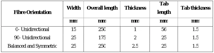
For the preparation of the specimen S-glass and Epoxy were selected. The test specimen was prepared as per ASTM standard D3038D / D3039M. Three samples of each specimen were prepared. The following Table 01 gives the recommended geometric dimensions of the test specimen.
Fibre Orientation Width Overall length Thickness
Tab
length Tab thickness
mm mm mm mm mm
0- Unidirectional 15 250 1 56 1.5
90- Unidirectional 25 175 2 25 1.5
Balanced and Symmetric 25 250 2.5 25 1.5
Table 01. Geometric Dimensions of the Test Specimen.
IV.
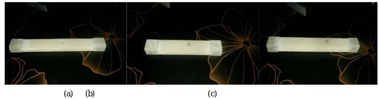
Fig. 01. Fabricated Specimens (a) 0 ° Orientation Specimens (b) 90 ° Orientation Specimens (c) 0 and 45 ° Orientation Specimens
The specimens prepared were tested in UTM as per ASTM standards. Results obtained such as UTS (Ultimate Tensile Strength), Displacement and strain etc. are obtained and are tabulated in the following table 02
Sample
no/coding Peak Load Break
Load Peak Disp Braeak Disp Initial Area Final Area
Reductionin Area
Engg UTS Strain
N N mm mm sq mm sq mm % Mpa
1.a 6031.300 6031.31 10.302 10.302 48.227 39.937 0.172 125.06 0.2080
1.b 5089.8 4619.1 8.639 8.69 56.452 48.031 0.149 90162 0.175
1.c 5236.9 49.035 9.428 9.513 56.195 47.213 0.1 93.192 0.19
2.a 7296.4 7296.41 10.862 10.862 76.496 62.382 0.18 95.382 0.22
2.b 6168.6 6168.6 10.862 10.862 75.223 61.72 0.18 82.004 0.219
2.c 7855.4 7767.14 11.999 12.059 75.313 60.604 0.195 104.3 0.243
3.a 7218 98.07 12.941 15.419 90.112 68.873 0.236 80.1 0.308
3.b 9875.6 490.35 15.3 39.579 82.742 59.28 0.284 119.36 0.396
3.c 7806.4 1677 11.965 13.866 93.343 73.077 0.217 83.631 0.277
Orientation 0
Orientation 90
Orientation 0 & 45
Table 02.Test Specimen Results
It can be observed from the table that unidirectional laminas have great strength compared to 0° and 45 ° lamina but their strain is slightly less than the former. So unidirectional laminas can be used where there is application of high strength and unsymmetrical angular lamina can be used where specific strain application are in need.
Following pictures show the results obtained after physical testing of the test specimens
(a) (b) (c) Fig. 02 Specimen Test Results (a) Sample 1.a Results (b) Sample 1.b Results (c) Sample 1.c Results
It can be seen that 0° unidirectional lamina has Ultimate Tensile Strength of 125.1 Mpa for sample 1.a.
(a) (b) (c)
Fig. 03 Specimen Test Results (a) Sample 2.a Results (b) Sample 2.b Results (c) Sample 2.c Results
It can be seen that 90° unidirectional lamina has Ultimate Tensile Strength of 125.1 Mpa for sample 2.b.
(a) (b) (c)
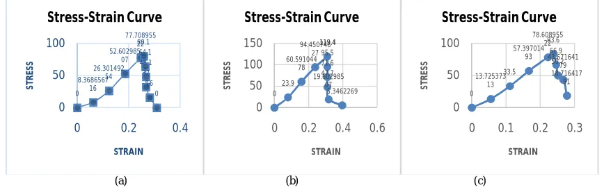
Fig.04Specimen Test Results Graphs (a) Sample 3.a Results (b) Sample 3.b Results (c) Sample 3.c Results.
011.038 36.79 55.2 91.98 125.1 0 50 100 150
0 0.1 0.2 0.3
ST R ES S STRAIN Stress-Strain Curve 010.7696 24.2316 43.0784 71.3486 90.2 0 50 100
0 0.1 0.2
ST R ES S STRAIN Stress-Strain Curve 0 8.346 32.827 57.9368.159 93.2 0 50 100
0 0.1 0.2
ST R ES S STRAIN Stress-Strain Curve 011.3904 28.4646.959 72.573 95.4 0 50 100 150
0 0.1 0.2 0.3
ST R ES S STRAIN Stress-Strain Curve 09.784 24.46 44.028 63.596 125.1 0 50 100 150
0 0.1 0.2 0.3
ST R ES S STRAIN Stress-Strain Curve 014.0103 31.134 52.9278 79.3917 125.1 0 50 100 150
0 0.1 0.2 0.3
ST R ES S STRAIN Stress-Strain Curve 0 8.3686567 16 26.301492 54 52.602985 07 77.708955 2280.1 64.1 48.1 32 16 0 0 50 100
0 0.2 0.4
ST R ES S STRAIN Stress-Strain Curve 0 23.9 60.591044 78 94.450746 27 119.4 119.4 95.5 71.6 47.7 19.602985 07 5.3462269 0 50 100 150
0 0.2 0.4 0.6
ST R ES S STRAIN Stress-Strain Curve 0 13.725373 13 33.5 57.397014 93 78.608955 2283.6 66.9 50.2 43.671641 79 18.716417 91 0 50 100
0 0.1 0.2 0.3
It can be seen that 0° and 45° lamina has Ultimate Tensile Strength of 119.4 Mpa for sample 3.b.
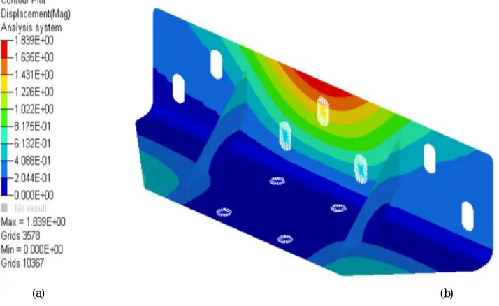
IV. SIMULATIONANDRESULTS
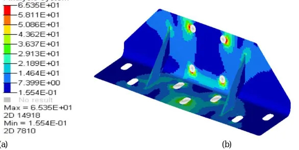
A structural bracket used to support structural loads has been FE analysed with mechanical Properties of Aluminium 6061 and S glass and Epoxy Composite with the help of computer aided softwares. For CAD modelling NX Unigraphics, for Analysis Hypermesh and Optistruct has been used. A maximum deflation of 0.0351 and 1.89 mm and Von Mises Stress of 81.92Mpa and 65.53 Mpa are observed with Aluminium and S Glass Epoxy Composite.
(a) (b)
Fig 05 Loads and Boundary Conditions (a) Showing force and constrained points (b) Showing Material orientation and load application in Composite Material.
(a) (b)
Fig 06Displacemet Plot (a) Numerical Values of Displacements for Composite (b) Graphical Representaion of Distribution of Displacement for Composite
(a) (b)
Fig 07 Displacemet Plot (a) Numerical Values of Displacements for Aluminium (b) Graphical Representaion of Distribution of Displacement for Aluminium
(a) (b)
Fig 08 Stress Plot (a) Numerical Values of Streses for Aluminium (b) Graphical Representaion of Distribution of Stresses for Aluminium
(a) (b)
V. THEORETICALVALIDATION
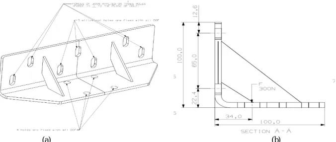
Theoretical Validation for the FE analysis is provided here. Results obtained from FE analysis are nearly matching theoritical calculations. The follwing Figures show the CAD modelling drafting of the structural bracket.
(a) (b) Fig 09 (a) CAD model Drafting of Structural Bracket (b) Sectional View at the Rib area
1. Stress
We know that bending moment and stress are related by following equation.
= =
Where Mb is the Moment of Bending. Iis Area Moment Of Inertia. isStress due to Bending. Y is distance of fibre
away from Neutral axis. E is Young’s Modulus. R is the radius of curvature.
Bending Moment Mb= 34 X 500
Mb=17000 N-mm
Consider = We know that Area moment of Inertia is given by I= ^ Cross Section dimensions are b = 100 mm, d = 6 mm
Therefore I= ∗ ^ =1800 mm4. At y = 3mm = »σ= »σ=28.33 Mpa
Applying notch sensitivity index at holes we getσ= σ ∗3 »σ= 28.33X3»σ=
2. Deflection
We know that deflection of cantilever beam with load at end is given by U= Substituting the values we get.
U= ∗
∗ ∗ ∗
ANALYTICAL AND FEA RESULT COMPARISON:
Aluminium 6061 S Glass/Epoxy Hand Calculation
Displacement
δ mm
Max 0.03511 1.839 0.05198
Min 0 0 -
Stress
σ N/mm2
Max 81.92 65.53 85
Min 0.121 0.155 -
Table. 03 Analytical and FEA Results comparison
VI. CONCLUSION
Looking at the results it can be concluded that composites materials made up glass epoxy polymer matrix can be used instead of conventional metals. They satisfy all the structural strength requirement. As PMCs help in reducing the weight and increasing the performance. They are durable and properties such as toughness and strength can be custom-made to match the applications they are required for. PMCs can be used in corrosive environment since they have excellent corrosion resistance compared to metals. With increase in the research on the composite materials and finding of more strength and durable composites, components made up of conventional metals can be replaced with composites.
REFERENCES
[1] Monali Deshmukh “Analysis and Optimization of Engine Mounting Bracket” International Journal of Scientific Engineering and Research (IJSER) ISSN (Online): Volume 3 Issue 5, May 2015, pp:2347-3878
[2] P. Thameem Banu “Modeling and Analysis of Bracket Assembly in Aerospace Industry” Journal of Engineering Research and Applications ISSN: 2248-9622, Vol. 5, Issue 6, (Part -1) June 2015, pp.04-08.
[3] Nikhil V Nayak “Composite Materials in Aerospace Applications” International Journal of Scientific and Research Publications, Volume 4, Issue 9, September 2014 ISSN 2250-3153.
[4] Sandeep M .B, D. Choudhary “Experimental study of effect of fiber orientation on the flexural strength of glass/epoxy composite material” IJRET: International Journal of Research in Engineering and Technology. Volume: 03 Issue: 09 | Sep-2014 eISSN: 2319-1163 | pISSN: 2321-7308.
[5] J. Olumuyiwa Agunsoye, Talabi S. Isaac, Sanni O. Samuel. “Study of Mechanical Behaviour of Coconut Shell Reinforced Polymer Matrix composite”Journal of Minerals and Materials Characterization and Engineering, voulume5, Issue 11, August 2012, pp: 774-779.
[6] SushilB.Chopade, Prof.K.M.Narkar, Pratik K Satav. “Design and Analysis of E-Glass/Epoxy Composite Monoleaf Spring for Light Vehicle” International Journal of Innovative Research in Science, Engineering and Technology Vol. 4, Issue 1, January 2015, pp: 18801-18808 [7] Vladimir Dmitrievich Vermel, Sergei Anatol ’evich Titov, Yuriy Vital evich Kornev. “Nano-modified Adhesive Composition for Aeronautical
Structures based on Polymer Composite Materials” Indian Journal of Science and Technology, Vol 8(S10), DOI: 10.17485/ijst/2015/v8iS10/84885, December 2015.ISSN (Print) : 0974-6846, ISSN (Online) : 0974-5645
[8] A. Asha,“Investigation on the Mechanical Properties of Egg Shell Powder Reinforced Polymeric Composites” International Journal of Engineering Research & Technology (IJERT) ISSN: 2278-0181, Vol. 3 Issue 12, December-2014, pp: 288-291.
[9] Haleh Allameh, Haery, Rizal Zahari Wahyu Kuntjoro and Yakub Md Taib “Tensile strength of notched woven fabric hybrid glass, carbon/epoxy composite laminates” Journal of Industrial textiles. 2014, Vol 43(3) 383–395 the Author(s) 2012.
[10] Layth Mohammed, Mohammad Jawaid, M. N. M. Ansari, M. Saiful Islam and Grace Pua. “A Review on Natural Fiber Reinforced Polymer Composite and Its Applications” Hindawi Publishing Corporation International Journal of Polymer Science Volume 2015, Article ID 243947. [11] Miquel Casafont, MagdalenaPastor, JordiBonada, FrancescRoure, TeomanPek¨oz, “Linear buckling analysis of perforated steel storage rack
columns with the Finite Strip Method”, Thin-Walled Structures, Vol.61, pp.71–85, 2012.