Active Power Factor Correction for DC-DC
Converter
Arpit D. Patel1 , Hardik Pandya2
P.G. Student, Department of Electrical Engineering, SCET, Surat, Gujarat, India1
Associate Professor, Department of Electrical Engineering, SCET, Surat, Gujarat, India2
ABSTRACT: Clear view of need of power factor correction is explained here. Bridgeless single phase DC-DC active power factor correction rectifier based CUK topology is described. It is also discussed the conventional types of power factor correction methods employed by the use of power electronic converters. This topology is operating into continuous (CCM) or discontinuous (DCM). By doing the power factor correction we get power factor nearer to unity and input current with low harmonics. Here we use CUK converter for power factor correction due to some advantages. Power supplies with power factor correction (PFC) is becoming necessary form many industrial purpose to meet harmonic regulation and good power quality.
KEYWORDS: DC-DC Converters, Power Factor Correction Techniques,THD,MATLAB
I. INTRODUCTION
In recent years Switch Mode Power Supply technologies (SMPS) are developed rapidly. In different application SMPS supplies are used as AC to DC sources for electronics products. But main disadvantages of this off line SMPS is that it draws a pulsating current so it has low power factor and high RMS line current. So, due to increasing demand of high power factor and good power quality Power Factor Correction is important part. Active Power Factor Correction (APFC) for DC-DC converters is economical and efficient.
In [1] they discussed the different DC converters topologies and their advantages and disadvantages. As these DC-DC converters are worked as a non-linear load so it is important to effect of non-linear load [2] and about harmonics and need of improving power factor. When DC-DC converters are operated in discontinuous conduction mode they have a self-power factor correction property which is described in the [3]. Method of improving power factor is active power factor correction which has different types with their own advantages and disadvantages [4]. The problem of low power factor can be improved by the power factor correction techniques. There are different power factor correction techniques here this paper discussed peak current control method [5].
Power converter with PFC works with high frequency and it draws a sinusoidal AC current which is in phase with AC input voltage. This APFC method is interposed between AC main and DC load. And non-linear load is appearing as a linear load for the AC line.
The main objective of this paper is the Power Factor Correction for CUK converter. If power factor of the system is poor then large amount of current is drawn from the supply. So, the power factor correction is essential in power system to achieving good power.
Advantages of CUK converter over other DC-DC converters are that output of Buck converter is always less than input and it requires an additional passive filter and output of buck converter is discontinuous and input current does not follow line voltage at zero crossing.
When Boost and SEPIC converters are operated the output of both converters are discontinuous with high ripple. The drawback of Buck-Boost converter is when it operated there is high current stress on semiconductor devices and discontinuous input current which increase the THD.
Compare to other converters cuk converter gives continuous input and output current with low current ripple and due to these advantages CUK converter is best candidate for the power factor correction.
II. RELATEDWORK
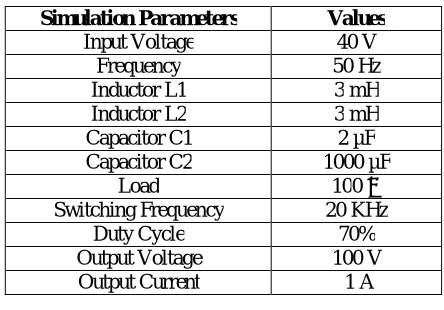
Due to the non-linear relationship of voltage and current all types of converters are producing harmonics. This harmonic distortion in current waveform will lead to poor power factor. Poor power factor increase the value RMS current, but the power delivered is small. So it is important task to improve power factor and reduce harmonics distortion to achieve good quality power. The parameter of cuk converter is given in Table 1. And Waveform obtain from this parameters are as shown in figure 2 and figure 3.
Simulation Parameters Values
Input Voltage 40 V
Frequency 50 Hz
Inductor L1 3 mH
Inductor L2 3 mH
Capacitor C1 2 µF
Capacitor C2 1000 µF
Load 100 Ω
Switching Frequency 20 KHz
Duty Cycle 70%
Output Voltage 100 V
Output Current 1 A
Table 1.Simulation Parameters . Power factor can be calculated by the equation:
2
1
. . * cos
1 P F THD
Where α is displacement factor at fundamental frequency and THD is Total Harmonic Distortion in input current. So to improve the power factor power factor correction method is used.
Power factor correction method is to improve power factor by suitable devices. The objective of power factor correction circuit is to make input power supply behave like purely resistive load.
There are two methods of Power factor correction methods: Passive Power Factor Correction Method
Active Power Factor Correction Method
Passive Power Factor Correction Method is used to improve the power factor for non-linear load. In this method we use only passive elements like capacitors and inductors to improve the nature of line current. But the size of passive elements will increase as the level of voltage is increase. And this method is used to improve power factor only up to 0. To 0.9, this is not used for industrial application.
Another important method to improve power factor is Active Power Factor Correction Method (APFC). This method is based on switch mode converter technique and is designed to compensate for distortion as well as displacement of input current waveform. Main advantages of this method is that we can improve power factor up to 0.99 by using this method and automatic correction of AC input voltage can be obtained.
There are four different methods of APFC as bellow:
(1) Peak current control method.
(2) Hysteresis current control method.
(3) Average current control method.
(4) Border line current control method.
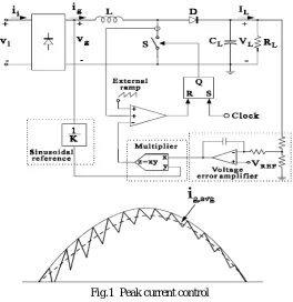
In this paper we discussed Peak current control method of APFC for improving the power factor for DC-DC cuk converter.
Advantages of Peak current control method:
(1) Constant switching frequency.
(2) No need of compensation ramp.
(3) Only switch current must be sensed and this can be accomplished by a current transformer.
Disadvantages of Peak current control method:
(1) Need of compensation ramp.
(2) Input current distortion increase at high line voltage and light load is distorted by a compensation ramp.
(3) Control is more sensitive to commutation noise.
Fig.1 Peak current control
III. SIMULATIONMODEL
From parameters which are given in Table we got output voltage is as shown in Figure 2.
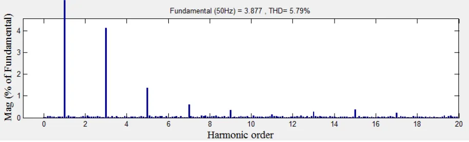
When the cuk converter is operated without power factor correction it draws high input current with high ripple. And input line current and voltage is also not in phase and it has low power factor which is undesirable for industrial application. The THD analysis for input current is given in Figure 3.
Fig.3 Input Current and Voltage Waveform
We can see that the without power factor correction there is a high harmonics in input current up to 55.21%. And power factor is also not unity. From Equitation we can calculate the power factor which is 0.8128 which is not unity.
Fig.4 THD analysis in cuk Converter
Discre te, Ts = 1e-006 s.
powergui
v +
-Vs
v+
-v + -A B +
-Universal Bridge
Scope S R Q !Q S-R Fli p-Fl op
Rload >= Rel ational Operator Product PI(s) PID Controller g D S Mosfet L2 L1 Input Voltage and Current [IL] [Gate] [Vin] [PI] -K-[IL] [Vi n] [Gate] [PI] m a k Dm boolean
Data Type Conversi on i
+ -i
+- 100
Constant1
Clock
C 2 C1
Add
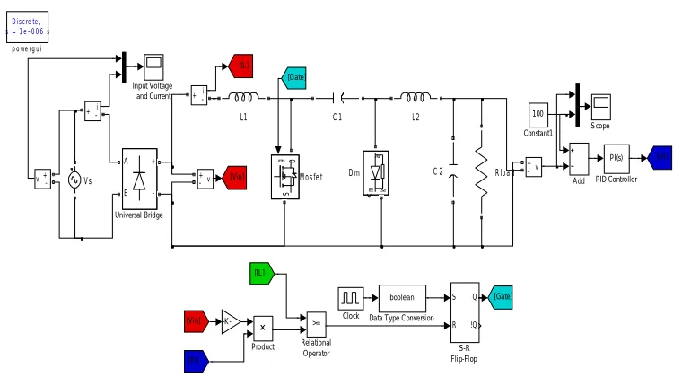
Fig. 5 Simulation of cuk converter with peak current control method
Input voltage and current is shown in figure 6. As shown in figure both voltage and current waveform is in phase with each other. By using this method the harmonics are also reduced from line current.
Fig. 6 Input voltage and current waveform for cuk converter with peak current control
Fig. 7 Input current THD for Open-loop configuration
IV. CONCLUSION
This paper discussed the detailed study about the harmonics and effect of non-linear load (DC-DC converter) on input line current and on power factor. Due to low power factor input line current has high harmonics and it is not in phase with the input line voltage so power factor is poor and it will draw pulsating line current. To overcome this problem power factor techniques are used which is also discussed in this paper. By using peak current control technique the input line current follows the input line voltage and unity power factor theoretically which is showed in MATLAB simulation in this paper.
REFERENCES
1. H.T.Yang, H.W.Chiang, C.Y.Chen,” Implementation of Bridgeless Cuk Power Pactor Corrector with Positive Output Voltage,” IEEE conference Power electronics, pp.2100-2107, May 2014.
2. D.Reddy, K.Pavankumar Goud, Pradeepkumar Reddy,” Analysis Of Different Topologies For Active Power Factor Correction Using DC-DC Converters,” IJATER, vol.4, Jan.2014.
3. H.Wei, I.Batarseh,”Comparison Of Basic Converter Topologies For Power Factor Correction,” IEEE conference, pp.348-353,1998. 4. L.Rossetto, G.Spiazzi, P.Tenti,” Control Techniques For Power Factor Correction Converters,” Proc. PEMC’94- 9, 1994.