IJEDR1402009
International Journal of Engineering Development and Research (www.ijedr.org)1370
Fuzzy Logic Based Power Quality Improvement
Using Shuntactive Filter
Mrs.Virali.P.Shah
M.E. [Electrical] Student, Department Of Electrical Engineering, LDRP Institute Of Technology, Ghandhinagar, Gujarat
________________________________________________________________________________________________________
Abstract— This paper describes a novel fuzzy logic controller for a three phase shunt active shunt filter for the power quality improvement. The Power Quality (PQ) problems in power distribution systems are not new but only recently the effects of these problems have gained public awareness. These non-linear loads are constructed by nonlinear devices in which the current is not proportional to the applied voltage. For the harmonic elimination different methods are used, but in this paper a novel fuzzy logic controller for a three-phase shunt active power filter for the power quality improvement such as reactive power and harmonic current compensation generated due to nonlinear loads. The approach of fuzzy logic control is linguistic description, so it does not require a mathematical model of the system. The application of the fuzzy logic controller to a three phase shunt active power filter is investigated. The controller is capable of controlling dc capacitor voltage and generating reference source currents. And this controller provides current compensation, such that the compensated current drawn from the network is sinusoidal and balanced, corresponding to the fundamental positive-sequence component of the load current, plus an additional fundamental positive positive-sequence component to cover losses in the power circuit of the shunt active filter. The results are found to be quite satisfactory to mitigate harmonic Distortions, reactive power compensation and power quality improvement.
Keywords— Non Linear Load, Power Quality, Shunt Active Filter, Series filter, Fuzzy Controller, harmonics, pi controller.
________________________________________________________________________________________________________
I. INTRODUCTION
One of main points in the development of alternating current transmission and distribution power systems at the end of the 19th century was based on sinusoidal voltage at constant-frequency generation. Sinusoidal voltage with constant frequency has made easier the design of transmission line and transformers. If the voltage were not sinusoidal, complications would appear in the design of transformers, machines, and transmission lines. These complications would not allow, certainly, such a development as the generalized ―electrification of the human society.‖ Today, there are very few communities in the worlds without ac power systems with ―constant‖ Voltage and frequency. If the current is not in phase with the voltage, and the average of this power over the cycle is zero, so reactive power will not contribute any power, it is wattles, and the power factor of the circuit should be high, it will be efficient and economical to have higher power factor, higher the power factor better the utilization of the circuit.
Now in this topic Non-linear loads connected to AC electric mains generate undesired harmonics in the current dynamics which are usually responsible of additional power losses and the risk of equipment damage or malfunctioning. In the last decades, the fast development of power electronics components and control processors has led to a growing interest in the so-called active power filters (APF).
Since power electronics was introduced, nonlinear loads that consume non sinusoidal Current have increased significantly. In some cases they represent very high percentage, the induction motor which is a linear load in steady state is now equipped with a rectifier and inverter for the purpose of adjustable speed control. The induction motor together with its drive is no longer a linear load.
There are two types of filter which are stated as series active filter and shunt active filter.
Series active filter consists of voltage series inverter along with the passive filter in the line, which injects regulated amount of voltages at the desired frequency. Series active filter must have current rating equal to worst load conditions. Active filters are therefore are not suitable for higher current ratings .The initial cost of the active filters is high
II. POWER QUALITY IN POWER DISTRIBUTION SYSTEMS
Most of the more important international standards define power quality as the physical characteristics of the electrical supply provided under normal operating conditions that do not disturb the customer’s processes. Therefore, a power quality problem exists if any voltage, current or frequency deviation results in a failure or in a bad operation of customer’s equipment.
However, it is important to notice that the quality of power supply implies basically voltage quality and supply reliability. Voltage quality problems relate to any failure of equipment due to deviations of the line voltage from its nominal characteristics, and the supply reliability is characterized by its adequacy (ability to supply the load), security (ability to withstand sudden disturbances such as system faults) and availability (focusing especially on long interruptions).
IJEDR1402009
International Journal of Engineering Development and Research (www.ijedr.org)1371
supply, for example when capacitors are switched may contribute substantially to power quality disturbances. Also, the connection of high power non-linear loads contributes to the generation of current and voltage harmonic components. Between the different voltage disturbances that can be produced. The most significant and critical power quality problems are voltage sags due to the high economical losses that can be generated. Short-term voltage drops (sags) can trip electrical drives or more sensitive equipment, leading to costly interruptions of production. For all these reasons, from the consumer point of view, power quality issues will become an increasingly important factor to consider in order satisfying good productivity. On other hand, for the electrical supply industry, the quality of power delivered will be one of the major factors for ensuring customer loyalty in this very competitive and deregulated market. To address the needs of energy consumers are trying to improve productivity through the reduction of power quality related process stoppages and energy suppliers are trying to maximize operating profits while keeping customers satisfied with supply quality, innovative technology provides the key to cost-effective power quality enhancements solutions.III. SOLUTIONS TO POWER QUALITY PROBLEMS
There are two approaches to the mitigation of power quality problems. The first approach is called load conditioning, which ensures that the equipment is less sensitive to power disturbances, allowing the operation even under significant voltage distortion. The other solution is to install line conditioning systems that suppress or counteracts the power system disturbances.
A flexible and versatile solution to voltage quality problems is offered by active power filters. Currently they are based on PWM converters and connect to low and medium voltage distribution system in shunt or in series. Series active power filters must operate in conjunction with shunt passive filters in order to compensate load current harmonics. Shunt active power filters operate as a controllable current source and series active power filters operates as a controllable voltage source.
Both schemes are implemented preferable with voltage source PWM inverters, with a dc bus having a reactive element such as a capacitor. Active power filters can perform one of the functions required to compensate power systems and improving power quality. As it will be illustrated in this paper, their performance depends on the power rating and the speed of response. The selection of the type of active power filter to improve power quality depends on the source of the problem as can be seen in Table I.
IV. FILTER STRUCTURE
Here there are two types of filters were described, which were given below;
A) PASSIVE FILTERS:
Use of passive filters is classic method for power quality improvement of distribution systems consist of series LC tuned for removing a specific harmonic or blocking a bandwidth of severe harmonics of nonlinear load current. These filters have low impedances for the tuned frequencies such as 5th and 7th and for these frequencies, the lower impedance of the filter in comparison with system impedance, the better filtering characteristics of passive filter. Low cost is a great benefit of these filters but because of their LC constant parameters, they cannot be efficient power quality improvement facilities for dynamic nonlinear loads. Another problem of installation of passive filters is probable resonances between the impedance of passive filter and the system resulting in increasing the harmonics and lower power quality of the distribution system. Passive filter are the most common harmonic filter in industrial application, the passive filter presents very low impedance at the harmonic frequency, through which all current of that particular frequency will be diverted. The design of the passive filter requires a precise knowledge of the harmonic producing load of the power system. A shunt filter is required to trap the harmonic current to correct the power factor of the load and properly filter the harmonics of the load. Shunt filters are usually more practical to use than series filters. Fig. 1 shows a simple example of a single frequency tuned filter having a very high admittance its tuned Frequency.
Active filter connection Load on AC supply AC supply on load
Shunt
-current harmonic filtering. -reactive current compensation. -Current unbalance.
-Voltage flickering.
series
-current harmonic filtering. -reactive current compensation. -current unbalance.
-voltage flickering. -voltage unbalance.
IJEDR1402009
International Journal of Engineering Development and Research (www.ijedr.org)1372
Fig. 1 Passive filterB) ACTIVE FILTERS
Active power filters have being developed since earlier, when one of the first prototypes based on instantaneous power theory was reported. Control strategies for active filters and active power line conditioners based on instantaneous active and reactive power theories developed. Since then, almost all controllers, for active power line conditioners and FACTS controllers use the p-q theory, as introduced and expanded for three-phase four wire systems. On the other hand, several works on active filter controllers based on synchronous reference frame.
Active filter controllers determine in real time the compensating current reference, and force power converter to synthesize it accurately. In this way active filtering can selective and adaptive. In other word, an active filter can compensate only for the harmonic current of selected nonlinear load, and continuously track change in its harmonic content.
C) TYPES OF ACTIVE POWER FILTERS
The technology of active power filter has been developed during the past two decades reaching maturity for harmonics compensation, reactive power, and voltage balance in ac power networks. All active power filters are developed with PWM converters (current source or voltage source inverters). The current-fed PWM inverter bridge structure behaves as a non-sinusoidal current source to meet the harmonic current requirement of the nonlinear load. It has a self-supported dc reactor that ensures the continuous circulation of the dc current. They present good reliability, but have important losses and require higher values of parallel capacitor filters at the ac terminals to remove unwanted current harmonics. Moreover, they cannot be used in multilevel or multistep modes configurations to allow compensation in higher power ratings.
The other converter used in active power filter topologies is the voltage-source PWM inverter. This converter is more convenient for active power filtering applications since it is lighter, cheaper, and expandable to multilevel and multistep versions, to improve its performance for high power rating compensation with lower switching frequencies. The PWM voltage source inverter has to be connected to the ac mains through coupling reactors. An electrolytic capacitor keeps a dc voltage constant and ripple free.
IJEDR1402009
International Journal of Engineering Development and Research (www.ijedr.org)1373
passive and active compensation.
NON LINEAR
LOAD AC mains
I I
Ic
Active filter
dc
Fig. 2 Shunt active power filter.
Shunt active power filters shown in Fig. 2 are widely used to compensate current harmonics, reactive power and load current unbalanced. It can also be used as a static var generator in power system networks for stabilizing and improving voltage profile.
NON LINEAR
LOAD
Series active filter
Ic
I AF I
DC AC mains
Fig. 3 Series active power filter.
Series active power filters shown in Fig. 3 is connected before the load in series with the ac mains, through a coupling transformer to eliminate voltage harmonics and to balance and regulate the terminal voltage of the load or line.
Non linear load
I
I
AF
DC Series active
filter
Fig. 4 Hybrid active power filter
The hybrid configuration is a combination of series active filter and passive shunt filter shown in Fig. 4. This topology is very convenient for the compensation of high power systems, because the rated power of the active filter is significantly reduced (about 10% of the load size), since the major part of the hybrid filter consists of the passive shunt LC filter used to compe nsate lower-order current harmonics and reactive power.
IJEDR1402009
International Journal of Engineering Development and Research (www.ijedr.org)1374
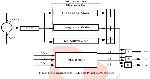
PI-Controller: Fig. 5 shows the block diagram of the proposed PI control scheme for the active power filter. The DC side capacitor voltage is sensed and compared with a reference voltage. This error e = Vdc, ref −Vdc at the nth sampling instant is used as input for PI controller. The error signal is passed through Butterworth design based Low Pass Filter (LPF). The LPF filter has cut-off frequency at 50 Hz that can suppress the higher order components and allows only fundamental components. The PI controller is estimate the magnitude of peak reference current Imax and control the dc-side capacitor voltage of voltage source inverter. Its transfer function is represented as, H (s) = Kp+ KI/SPID Controller: Fig 5 shows the block diagram of the proposed Proportional Integrator Derivative (PID) control scheme of an active power filter. The error e = Vdc,ref −Vdc at the nth sampling instant is used as input for PID controller. The error signal is passed through LPF; that can suppress the higher order components and pass only the fundamental component.
LPF
Propotional Gain
Integration Gain
Derivative Gain
X
X X PLL circuit
isa*
isb*
isc* Ia1
Ib1
Ic1 Vsa
Vsb
Vsc Vdc,ref
Vdc +
-PI- controller PID controller
Fig. 5 Block diagram of the PLL with PI and PID Controller
The PID controller is a linear combination of the P, I and D controller. Its transfer function can be represented as H(s) = Kp+KI/S+KD(S)
Where, KP is the proportional constant that determines the dynamic response of the Dc-side voltage control, KI is the integration the derivative of the error representing the trends. The controller is tuned with proper gain for estimating the magnitude of peak reference current Imax and control the dc-side capacitor voltage of inverter. The peak reference current multiplied with PLL output determines the desired reference current.
Fuzzy Logic Controller
IJEDR1402009
International Journal of Engineering Development and Research (www.ijedr.org)1375
LPF
Integrator
Rule Base
Fuzzyfication Rule Elevator Defuzzification
Data Base Vdc,ref
Vdc +
-Imax
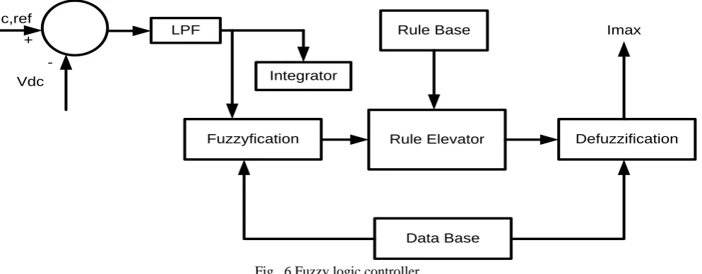
Fig. 6 Fuzzy logic controller
Fuzzification
Fuzzy logic uses linguistic variables instead of numerical variables. In a control system, error between reference signal and output signal can be assigned as Negative Big (NB), Negative Medium (NM), Negative Small (NS), Zero (ZE), Positive small (PS), Positive Medium (PM), Positive Big (PB). The triangular membership function is used for fuzzification. The process of fuzzification convert numerical variable (real number) to a linguistic variable (fuzzy number).
Rule Elevator
Conventional controllers like PI and PID have control gains which are numerical values. Fuzzy logic controller uses linguistic variables instead of the numerical values. The basic fuzzy logic controller operation uses the following fuzzy set rules to control the system
Defuzzification
The rules of fuzzy logic controller generate required output in a linguistic variable (Fuzzy Number), according to real world requirements; linguistic variables have to be transformed to crisp output (Real number). This selection of strategy is a compromise between accuracy and computational intensity.
Database
The Database stores the definition of the triangular membership function required by fuzzifier and defuzzifier.
Rule Base
The Rule base stores the linguistic control rules required by rule evaluator (decision making logic). The rules used in this proposed controller are shown in table II.
The output of the fuzzy controller is estimating the magnitude of peak reference current Imax. This current Imax comprises active power demand of the non-linear load and losses in the distribution system. The peak reference current is multiplied with PLL output for determining the desired reference current.
V. ACKNOWLEDGMENT
A FUZZY LOGIC BASED POWER QUALITY IMPROVEMENT USING SHUNT ACTIVE FILTER’’‖ concludes my work carried out at the Department of Electrical Engineering, L.D.R.P Engineering College, Gandhinagar. First of all, I would like to express my gratitude to my supervisor Mr.Maulik pandya for faithtful discussions, guidance and encouragement throughout this thesis as well as valuable comments on this document. I would also like to thanks Prof.H.N Prajapati, Head, Electrical Engineering Department, for their support as Head of Department.
VI. CONCLUSION
A fuzzy logic controller is implemented for three phase shunt active power filter to obtain dc capacitor voltage and the reference currents. This facilitates to improve the power quality parameters such as reactive power and harmonics due to nonlinear load. The fuzzy logic controller is a good candidate for controlling active power filter to solve power quality issues. Approach of fuzzy logic control is linguistic description, so it does not require a mathematical model of system.
VII. REFERENCES
[1] Fuzzy controller shunt active filter for power quality improvement E Latha Mercy, R.karthickand S. Arumugam
[2] Fuzzy Logic Controller Adaptive Active power filter for Harmonics Minimization and Reactive power compensation under fast load variation. A.ghasemi, S,S mortazavi, R.kianinezhad (Department of electrical engineering sahib chairman university golestan boulevard-Ahvaz IRAN
[3] Fuzzy Logic Controller Adaptive Active power filter for Harmonics Minimization and Reactive power compensation under fast load variation. Karuppanan p & kamalakanta mahapatra dept. of national institute of technology- Rourkela, india-769008. (International conference on advance in energy conversion technologies (ICAECT 2010), jan07-10-2010).
IJEDR1402009
International Journal of Engineering Development and Research (www.ijedr.org)1376
GNIT, hydra bad, mail. (Journal of theoretical and applied information technology, 2005-2011 jatit & lls. All rights reserved) [5] Active filter for power quality improvement. Joao l. fonso, member IEEE, H.J ribeiro de Silva and Julio s.martins, memberIEEE (2001 IEEE Porto powertech, 10-13 set. 2001, Porto, Portugal, ISBN :0 7803 7139 9)
[6] Simulation result of a shunt active power filter with control based on p-q theory. Emilio F. couta, julioS.martins, Joao L. Alonso department of industrial electronic university of Minho.
[7] Fuzzy logic control based three phase shunt active filter for voltage regulation and harmonics reduction. G.jaykrishn (department of electrical and electronics engg. Siddhartha institute of engg. And technology putter, chittoor (dist), adhrapradesh, India. And K.S.R. anjaneyulu (professor of electrical & electronics enggs director, research &development cell, Jawaharlal Nehru technological university, anantapur, India. International journal of computer application 0975-8887) volume 10-no.5 November 2010.
[8] ―A Control Strategy for Shunt Active‖ Filter Mauricio Aredes and Luis F. C. Montero UFRJ − Federal University of Rio de Janeiro.
[9] Using active power filters to improve power quality. (Department de Ing. Electrical Universidad de Concepción Concepción – CHILE & Department de Ing. Electrical Universidad Catholic de Chile Universidad Católica de Chile)
[10]A review of active filter for power quality improvement. Bhim Singh, Kamal Al-Haddad, Senior Member, IEEE, and Ambrish Chandra, Member, IEEE
[11]power quality improvement using system . PhD Supervisor, Prof.PhD.eng. Virgil MAIER
[12]A review of active filter for power quality improvement. Bhim Singh, Kamal Al-Haddad, Senior Member, IEEE, and Ambrish Chandra, Member, IEEE