Copyright to IJIRSET www.ijirset.com 702
ISSN (Online): 2319-8753 ISSN(Print): 2347 - 6710
I
nternationalJ
ournal ofI
nnovativeR
esearch inS
cience,E
ngineering andT
echnologyAn ISO 3297: 2007 Certified Organization, Volume 2, Special Issue 1, December 2013
Proceedings of International Conference on Energy and Environment-2013 (ICEE 2013)
On 12th to 14th December Organized by
Department of Civil Engineering and Mechanical Engineering of Rajiv Gandhi Institute of Technology, Kottayam, Kerala, India
NUMERICAL ANALYSIS OF TWO PHASE FLOW
IN FLAT HEAT PIPE
RakeshHari, C. Muraleedharan
Research Scholar, Dept. of Mechanical Engineering, NIT Calicut, Kerala, 673601. India Professor, Dept. of Mechanical Engineering, NIT Calicut, Kerala, 673601. India
ABSTRACT
Heat pipe is a thermodynamic device of very high thermal conductance. In a heat pipe the working fluid experiences phase change both in the evaporator and condenser sections. The flat heat pipe (FHP) is a transmutation of the conventional heat pipes that finds applications to deal with high density electronic cooling problem due to their high thermal conductivity and reliability where large heat flux is to be transported through limited space. The paper presents a numerical analysis of phase changephenomenon in a flat heat pipe. The heat pipe modeling involves the principal physical processes of wick-liquid dynamics and movement of resulting vapour away from the evaporator through the heat pipe vapour space to the condenser. The analysis involves the simultaneous solution of two dimensional continuity, momentum and energy equations in the liquid wick and the vapour core regions with respective boundary conditions.Vapour flow in the vapour passage is assumed to be laminar and the heat dissipation at the condenser side is by forced convection. The axial velocity distributions and velocity vector plots are obtained along the vapour core and liquid wick region at steady state conditions. Two phase mixture model is formulated to investigate the phase change phenomena in the porous wick structure. The flow equations for liquid-vapour interface are solved using appropriate numerical technique.Nusselt number and Sherwood Number are plotted against wall saturation for boiling and condensation.
NOMENCLATURE
d Liquid wick thickness, m h Vapour Core Thickness, m k Thermal Conductivity, W/mK K Wick Permeability, m2
L Length of Heat Pipe, m P Pressure, Pa
s Saturation t Time, s
Copyright to IJIRSET www.ijirset.com 703 v Transverse Velocity, m/s
x Axial Distance, m y Transverse Distance, m
ε Porosity
μ Dynamic Viscosity, Ns/m2
ρ Density, kg/m3
φ Viscous Dissipation
Subscripts a Adiabatic c Condenser e Evaporator
1. INTRODUCTION
In recent years flat heat pipes (FHP) are widely used for electronics and space craft cooling applications due to their high heat transport capability, effective performance and adaptable structure. A flat heat pipe is an enclosed chamber whose inner surfaces are lined with a capillary wick structure with the remaining volume containing vapour. The working fluid is vaporized by the external heat source at the evaporator, the generated pressure difference drives vapor from the evaporator to the condenser, where it condenses and enters the wick structure. The capillary pressure in the wick pumps the condensed liquid back to the evaporator for re-evaporation. This internal phase-change circulation will continue as long as flow passage is not blocked and sufficient capillary pressure is maintained. To face the new challenges in electronic cooling, the heat transfer limit need to be increased by optimizing the geometric and operating parameters. Compared to small cylindrical heat pipes, flat heat pipes can be easily fixed onto PCB cooling device, because of the thickness shrinking. The thickness of the FHP can be made in the range of a few millimeters depending on the wick structure type, which can reduce the space of cooling devices significantly.
Copyright to IJIRSET www.ijirset.com 704 unidirectional circulation condition are numerically investigated and discussed. Wang et al. [8] in their experiment investigated the effect of evaporation and condensation length on the thermal performance of the flat heat pipes. The results showed that, the thermal resistance decreased and the heat transfer limit increased with the increase of evaporation section length, and similarly the increase in the condensation section length would make the heat pipe dry out at a lower heating power, which indicated the decrease in heat transfer limit.
2. THE PHYSICAL MODEL
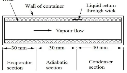
A schematic diagram of the flat heat pipe analyzed, including dimensions of each region is shown in the Figure 1. Working fluid chosen for the present analysis is water. The wick and wall material is assumed as copper. The porosity of wick is taken as 0.6 for the analysis, with the voids saturated with water. A uniform heat flux of 50 W/m2 is applied externally at the evaporator section, while the condenser section is cooled by imposing a heat transfer coefficient of 1000 W/m2K,at the condenser end with the initial temperature of 300 K. The adiabatic section is assumed to be insulated such that there is no heat transfer between this region and the atmosphere.
Figure 1. SCHEMATIC OF HEAT PIPECONSIDERED
The assumptions in the model include: non-existence of body forces; two-dimensional flow fields; flow is laminar and incompressible; vapour is a saturated ideal gas, and thermodynamic equilibrium prevails at the vapour liquid interface.
Thermo-physical properties of the heat pipe material and working fluid are shown in Table 1. The thermo-physical properties are considered to be constant as the variations are negligible over the operating temperature range considered.
3. THE MATHEMATICAL MODELLING
The governing equations i.e. continuity, momentum and energy equations for vapour flow in fundamental variables for a laminar, two dimensional flow in a heat pipe is given as:
For vapour core:
+ = 0 (1)
Copyright to IJIRSET www.ijirset.com 705
+ + =− + + (3)
( ) + + = + + + + +∅ (4)
where,
∅= 2 + + +
For the liquid wick:
The governing equations are
+ = 0 (5)
+ u + v =− + + − − . | | (6)
+ + =− + + − − . | | (7)
( ) + ( ) + = + (8)
Boundary Conditions For vapor core:
At x=0, y=0 to h, u=0, v=0, At x=L, y=0 to h, u=0, v=0
At y=0, 0 ≤ x ≤ Le, u=0, v=vo, dT/dy=q/k At y=h, 0 ≤ x ≤ Le, u=0, v=-vo,dT/dy=-q/k
At y=0, Le≤ x ≤ (Le+La) u=0, v=0,dT/dy=0 At y=h, Le≤ x ≤ (Le+La) u=0, v=0,dT/dy=0
At y=0, La≤ x ≤ Lc, u=0, v=-vo,T=Tc At y=h, La≤ x ≤ Lc, u=0, v=vo,T=Tc
At x=0, y=0 to h, dT/dx=0 At x=L, y=0 to h, dT/dx=0 For liquid wick:
At y= -d, x=0 to L, u=0, v=0 At y= (h+d), x=0 to L, u=0, v=0
Initial Condition
At time t = 0, T = Tamb, and in the liquid and vapourp=psat
Table 1. THERMOPHYSICAL PROPERTIES OF THE HEAT PIPE MATERIAL AND WORKING FLUID
Thermalconductivity (W/m K)
Specific Heat (J/kg K)
Density (kg/m3)
Viscosity (Ns/m2)
Latent heat ofvaporization
(kJ/kg) Copper
(wall/wick)
401 385 8978 - -
Water 0.608 4182 998 0.001003 -
Copyright to IJIRSET www.ijirset.com 706 4. CFD SIMULATION
Properties of liquid are considered to be constant throughout the simulation. Since the operating pressure inside the heat pipe is low corresponding to saturation temperature of the fluid, the density variation of the vapour can be calculated by ideal gas equation. Vapourflow in the vapour core region is assumed to be in laminar. Liquid flow though the wick is considered to be laminar and incompressible. Heat rejection at the condenser side is by imposing forced convection.The simulation of flow through the heat pipe is modeled by CFD software package ANSYS Fluent. The user defined functions (UDF) are linked to invoke the heat and mass transfer phenomena happening inside the flat heat pipe. Steady state operation of the heat pipe is achieved starting from transient simulation. Calculations are performed by combination of the SIMPLE algorithm for pressure–velocity coupling and a first-order upwind calculation scheme for the determination of momentum, volume fraction and energy. Convergence is based on the residual value of the calculated variables, namely mass, velocity components, volume fraction and temperature.
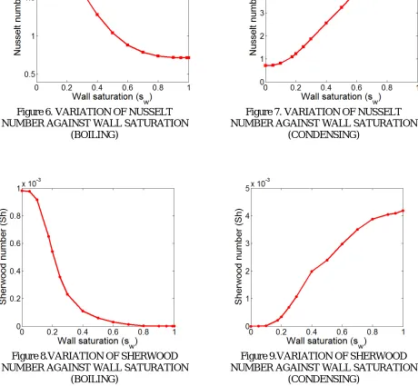
Assuming a two-phase zone of liquid and vapour phase co-exist and appear adjacent to the conducting wall of porous media, the phase change phenomena is obtained with the respective phase change equations. Taking into consideration that as the heat transfer at the wall gradually enhances, the liquid saturation at the wall approaches its limiting value, zero for boiling and one for condensation. Nusselt number which is a measure of heat transfer coefficient is found out for two phase region of both the evaporator and condenser section. Sherwood number which gives the measure of wall liquid flux and it also specifies the dimensionless phase change rate at the wall, is also computed for both the cases.
Numerical computation is considered to be converged when the scaled residuals of the variables mass, velocity components and volume fraction have lowered by six orders of magnitude and when the residuals of the temperature variable have lowered by seven orders of magnitude.
5. RESULTS AND DISCUSSION
Steady State Performance
The variation of velocity in the vapour core region along the center line is shown in the Figure 2. It can be observed that the vapour velocity monotonically increases in the evaporator section, which is due to the addition of the vapour formed. Similarly there is a fall in the velocity along the condenser section which is due to the mass depletion. The velocity in the adiabatic region is found to be almost constant and is substantially larger than that elsewhere.
Copyright to IJIRSET www.ijirset.com 707 Figure 3. LIQUID VELOCITY ALONG THE WICKCENTERLINE
The variation of liquid velocity in the wick regionalong the length of the heat pipe, for a wick porosity of0.6 is shown in Figure 3. The liquid velocity increasesfrom the condenser to adiabatic region, where it isalmost constant and there after decreases along theevaporator length. The magnitude of the liquid velocityis more than a hundred times smaller than the vapourvelocity in the core due to the liquid-vapour densitydifference.
Figure 4. VELOCITY VECTOR AT STEADY STATE IN THE VAPOUR CORE
Figure 5. VELOCITY VECTOR AT STEADY STATE IN THE WICK
Copyright to IJIRSET www.ijirset.com 708 Nusselt number represents the effectiveness of heat convection at the surface which is plotted against wall saturation for boiling and condensing flows andshown in Figures 6 and 7. For boiling its value goes on decreasing with the increase in wall saturation and it approaches a value of 1.For condensing flow,Nusselt number has a finite value at zero wall saturation. It increases with wall liquid saturation and reaches the maximum value at wall saturation equals unity.
Figure 6. VARIATION OF NUSSELT NUMBER AGAINST WALL SATURATION
(BOILING)
Figure 7. VARIATION OF NUSSELT NUMBER AGAINST WALL SATURATION
(CONDENSING)
Figure 8.VARIATION OF SHERWOOD NUMBER AGAINST WALL SATURATION
(BOILING)
Figure 9.VARIATION OF SHERWOOD NUMBER AGAINST WALL SATURATION
(CONDENSING)
Copyright to IJIRSET www.ijirset.com 703 zero when the wall saturation is zero and increases with wall saturation and finally reaches maximum value when the wall saturation is unity, which corresponds to maximum heat transfer rate.
6. SUMMARY AND CONCLUSION
In the present work, a two dimensional steady state model of flat heat pipe is numerically analyzed to solve the variation of velocity field in the liquid wick and the vapour core region, for a constant heat flux. The effect of fluid flow through the vapour core and wick which causes heat to flow is brought out in the analysis. The flow in the capillary porous media is solved using two-phase mixture model. The variation of Nusselt number and Sherwood number against the wall saturation for both boiling and condensing flows are obtained. It isalso concluded that the flat heat pipe successfully spreads the heat uniformly at the condenser side of the structure.
REFERENCES
[1] Bin Xiao., Amir Faghri., 2008. “A three dimensional thermal-fluid analysis of flat heat pipes”. Int.Journal of Heat and Mass Transfer, 51, pp. 3113-3126.
[2] Sobhan, C, B., Garimella, S, V., and Unnikrishnan, V, V., 2000. “A computational model for the transient analysis of flat heat pipes”. Inter Society Conference on thermal phenomena, pp.106-113.
[3] Mehta, R, C., Jayachandran, T., 1996. “Numerical analysis of transient two phase flow in heat pipe”. Heat and Mass Transfer, 31, pp. 383-386.
[4] Wang, C,Y.,Beckermann, C,1995, “Boundary layer analysis of two-phase flow in capillary porous medium”, ASME Journal of Heat Transfer, Vol.117,pp.1082-1087.
[5] Unnikrishnan, V, V., and Sobhan, C, B., 1997. “Finite difference analysis of the transient performance of a flat heat pipe”. Proc. of the Tenth Int. Conf. for Numerical methods in Thermal problems, UK, pp.391-402.
[6] TaoufikBrahim.,AbdelmajidJemni. 2012. “Heat pipe Simulation under critical conditions”. Frontiers in Heat Pipes.
[7] DehaoXu.,Taofei Chen., YiminXuan. 2012. “Thermo-hydrodynamics analysis of vapor-liquid two-phase flow in the flat-plate pulsating heat pipe”. International communications in Heat and Mass Transfer, 39, pp. 504-508