Garbled RAM From One-Way Functions
Sanjam Garg∗ Steve Lu† Rafail Ostrovsky‡ Alessandra Scafuro§
Abstract
Yao’s garbled circuit construction is a fundamental construction in cryptography and recent effi-ciency optimizations have brought it much closer to practice. However these constructions work only for circuits and garbling a RAM program involves the inefficient process of first converting it into a circuit. Towards the goal of avoiding this inefficiency, Lu and Ostrovsky (Eurocrypt 2013) introduced the notion of “garbled RAM” as a method to garble RAM programs directly. It can be seen as a RAM analogue of Yao’s garbled circuits such that, the size of the garbled program and the time it takes to create and evaluate it, is proportional only to the running time on the RAM program rather than its circuit size.
Known realizations of this primitive, either need to rely on strong computational assumptions or do not achieve the aforementioned efficiency (Gentry, Halevi, Lu, Ostrovsky, Raykova and Wichs, EURO-CRYPT 2014). In this paper we provide the first construction with strictly poly-logarithmic overhead in both space and time based only on the minimal and necessary assumption that one-way functions ex-ist. Our scheme allows for garbling multiple programs being executed on a persistent database, and has the additional feature that the program garbling is decoupled from the database garbling. This allows a client to provide multiple garbled programs to the server as part of a pre-processing phase and then later determine the order and the inputs on which these programs are to be executed, doing work independent of the running times of the programs itself.
∗
University of California, Berkeley. Computer Science [email protected]
†
University of California, Los Angeles. Department of Computer [email protected]
‡
University of California, Los Angeles. Department of Computer Science and [email protected]
§
1
Introduction
As individuals and organizations push massive amounts of personal data and the associated computational demands to the cloud, guaranteeing privacy of this data wile simultaneously enabling easy access to it poses tremendous challenges. Consider the following concrete problem. A client, say Alice, wants to store a large private dataset or databaseDon an untrusted server, referred to as “the cloud." Subsequently, Alice wants the cloud to be able to compute and learn the output of arbitrary dynamically chosen private programsP1, P2, . . . on private inputsx1, x2, . . .and the previously stored dataset, which gets updated as these programs are executed. Furthermore, Alice wants to achieve this non-interactively, i.e. by sending just one message for each program/input to the server.
Solutions using Yao’s Garbled Circuits or Fully Homomorphic Encryption. The first feasibility solu-tion for this problem was provided by Yao [Yao82]. However Yao’s approach requires that the program be first converted to a circuit — the size of which will need to grow at least with the size of the input. Hence for each program that Alice wants the cloud to compute, it will need to send a message that grows with the size of the database. A potential attempt to mitigate this is to use Fully Homomorphic Encryption, first provided by Gentry [Gen09]. While this reduces the size of Alice’s message, the cloud still needs to touch the entire encrypted database. Consequently the work of the cloud still grows with the size of the database. These solutions can be prohibitive for various applications, e.g. for binary search the size of the database can be exponentially larger than execution path of the insecure solution. We note that additionally even in settings where the size of the database is small, generic transformations from RAM programs with running timeT
result in a circuit of sizeO(T3logT)[CR73,PF79], which can be prohibitively inefficient.
Garbled RAMs. Motivated by the above considerations, Lu and Ostrovsky [LO13b] introduced the notion of garbled random-access machines (garbled RAMs) as a method to garble RAM programs directly. Garbled RAMs can be seen as a RAM analogue of Yao’s garbled circuits, such that the size of the garbled program, the time it takes to create and evaluate it is proportional only to the running time on the RAM pogram (up to poly-logarithmic factors), rather than the size of its circuit representation.
In more detail, we will use the notation PD(x)to denote the execution of some RAM program P on
inputxwith initial memoryD. A garbled RAM scheme should provide a mechanism to garble the dataD
into garbled dataD˜, the programP into garbled programP˜ and the inputxinto garbled inputx˜such that givenD,˜ P˜andx˜allows for computingPD(x)and nothing more. Furthermore, up to only poly-logarithmic
factors in the running time of the RAMPD(x)and the size ofD, we require that the size of garbled data ˜
Dis proportional only to the size of dataD, the size of the garbled inputx˜is proportional only to that of
xand the size and the evaluation time of the garbled programP˜ is proportional only to the running time of the RAMPD(x).
Both the original Lu and Ostrovsky [LO13b] construction and its follow up [GHRW14a,LO14,GHL+14] need to make strong computational assumptions for achieving the above described efficiency goals. In par-ticular, the security of the original Lu-Ostrovsky relies on a somewhat complex “circular” assumption in-volving Yao garbled circuits and PRFs and the Gentry et al. [GHRW14a] construction uses identity-based encryption (IBE). Lu and Ostrovsky [LO14] describe an alternative construction based just on one-way functions but that does not meet the above mentioned efficiency goals. Specifically for this solution, the size of the garbled program grows by an additional factor of|D|for a constant >0, which can be prohibitive
for the envisioned applications. These works leave open the following problem.
1.1 Our Results
In this paper we provide the first construction of an efficient garbled RAM that can be based on one-way functions alone, thus making it a suitable replacement for Yao’s garbled circuits with the added benefits of being in the RAM model. We state this as our main theorem:
Main Theorem (Informal). Assuming one-way functions, there exists a secure garbled RAM scheme, where the size of the garbled database is|D| ·poly(κ), size of the garbled input is|x| ·poly(κ)and the size of the garbled program and its evaluation time isT ·poly(logT,log|D|, κ)whereT is the running time of programP. Hereκis the security parameter.
Our contribution also includes an interesting strengthening of the garbled RAM definition where gar-bling the database is decoupled from the gargar-bling of the program, and only tied together by the gargar-bling of the input. Our constructions do achieve this stronger definition. We believe this will be of independent interest in various outsourcing computation applications. We provide a motivating example application to the pre-processing model below.
Persistent Garbled Database. Just as in previous works, our construction allows for execution of multiple programs on the garbled memory, such that the running time of the client and the server per program is proportional to the RAM runtime of that program. Furthermore the garbled database is persistent in the sense that the modifications made to it by the execution of garbled programs are maintained across different program executions. At the same time an attacker can not execute programs out of order, replay old garbled databases to new programs, or modifying the underlying contents of the garbled database beyond what is dictated by the GRAM evaluation algorithm.
Preprocessing Model. A nice feature of our solution is that the online work of a client can be further reduced when preprocessing is allowed. In more detail, consider a setting where in a preprocessing phase the client provides the cloud, not just a garbled database but also a set of garbled programs that she might want to execute in the future. Subsequently during the online phase she can dynamically decide the execution order of her previously garbled programs, and execute them on inputs of her choice. A nice feature of this solution is that the clients online overhead for executing a program reduces just to the size of the private inputs (with a poly(κ) overhead), completely independent of the size of the data and the running time of the programs. Technical this becomes possible because of the decoupling of data garbling from program garbling.
Input-specific running time. If one is willing to disclose the exact running time of a specific execution, then the running time of a garbled RAM computation can be made input specific which could be much faster than the worst-case running time. This was first explicitly explored by Goldwasser et al. [GKP+13] in the context of secure TM computation. This applies to a wide range of algorithms that have a gap between “typical”-case and worst-case time complexity, including randomized algorithms which could have exponential worst-case running time (Las Vegas), or heuristic algorithms that perform well in practice.
In our setting, the client can garble a sequence of generic CPU steps and provide them to the cloud. Later on, the client just needs to provide a short garbled input, which allows the cloud to do the computation in input specific running time. Interestingly this only consumes garbled CPU steps proportional to the input specific running time and the left over CPU steps can be used for executing the next program. In other words the clients overall work will be proportional only to the sum of the input-specific running times of the programs it executes with the server.
Secure RAM Computation. Much like how garbled circuits can be applied to secure circuit computation, so can garbled RAM be used for secure RAM computation. This allows us to perform one-round secure RAM computation in the OT-hybrid model.Our construction permits the secure computation of multiple RAM programs on a persistent database, although we do not allow the inputs to be chosen adaptively by an attacker (a weakness that is present in, and inherited from garbled circuits). Furthermore, we inherit many of the optimizations found in garbled circuits, for example, garbled input in our construction can be compressed from|x| ·poly(κ)to|x|+poly(κ)via [AIKW13].
2
Our Techniques
The starting point for our work is the garbled RAM construction of Lu and Ostrovsky [LO13b]. Though the security of this construction is based on a strong and somewhat complex “circular” assumptions involv-ing Yao garbled circuits and PRFs, it serves as a good startinvolv-ing point in explaininvolv-ing the ideas behind our construction based on one-way functions.
Starting point — Lu-Ostrovsky construction. The Lu-Ostrovsky construction views the program P, to be garbled, as a sequence of T CPU steps. Each of these CPU steps is represented as a circuit. Each CPU step reads or writes one bit of the RAM, which stores some datasetD. In order to keep this intuitive description simple, we will restrict ourselves to RAM programs that only read from memory and also to the weaker security requirement of unprotected memory access (UMA) in which we do not try to hide the database being stored or the memory locations being accessed (only the program and input is hidden). As noted in previous works [LO13b,GHL+14] this weaker security guarantee can be amplified to full security by using oblivious RAM. Garbling the RAM program itself involves just garbling theT CPU step circuits, using a circuit garbling scheme, e.g. Yao [Yao82]. The novelty is the added functionality of the ability to read bits from arbitrary memory locations without knowing them in advance or using interaction.
For each memory locationi, containing valuebi the valueFs(i, bi)is stored in the “garbled” memory, wheresis a secret PRF key. Let’s consider that a CPU step that wants to read memory locationithat needs to be fed into the next CPU step. Note that both these circuits will be independently garbled using Yao’s garbled circuit technique. Letlabel0andlabel1 be the garbled input wire labels corresponding to the wire for the read bit of the second circuit. In order to enable evaluation of the second garbled circuit, we need to be able to revealexactly oneof these two labels, corresponding tobi, to the evaluator. Note that the first
garbled circuit needs to do this without knowingiandbi at the time of garbling. The idea for enabling the read is for the first garbled circuit to produce a translation gadget: the first garbled circuit outputs encryptions of labelslabel0 andlabel1 under keys Fs(i,0)andFs(i,1)respectively. Since the evaluator holding the
garbled memory only has one of the two valuesFs(i,0)orFs(i,1)at his disposal, he can only obtain either
label0orlabel1. This enables the evaluator to feed the proper bit into the next CPU step and continue the evaluation. Again we note here that since the locationithat needs to be read is generated dynamically at runtime, we need the CPU step to be able to generate PRF valuesFs(i,0)andFs(i,1)dynamically, and in order to enable this computation we need to hardwire the secret keysin each of these CPU step circuits that are being garbled.
Circularity Assumption. As noted in [GHRW14a], in arguing security of the above scheme we need to rely of the security of Yao’s garbled circuit, which in turn needs that only one label for each of its input wires is given out. Finally this needs to rely on the pseudorandomness property of the outputs ofF. However the problem is that the key of the PRFs, is embedded inside the garbled circuits. Because of this circularity, the security of this construction requires a somewhat complicated assumption.
not the current and past ones, breaking the circularity. Unfortunately, these solutions either require stronger assumptions, namely IBE [BF01], or more overhead that do not meet our poly-logarithmic efficiency goals. There appears to be a fundamental barrier in all previous schemes: to read a value from a memory location, we need to have a key hardcoded in the garbled circuits that produces two values for any memory location, one of which is in the garbled memory. At the same time we need to claim that the value not in memory is indistinguishable for random in order to use Yao’s security for the next garbled circuit. Given that we do not want to assume circularity the need to successively weaker keys seems unavoidable. The main technical question is how can we overcome this dependency without necessarily having to weaken keys?
Our Idea. Our main idea is to replace the process of key revocation, with the idea ofkey evolution. Data garbling in previous constructions was done using one master key that encrypted everything, and weakenings of which were hardcoded inside different garbled circuits, in an attempt to break circularity. Our strategy will be to have multiple keys, more explicitly a key tree, and anytime a key is used in a way that might effect the security of the later garbled circuits, then we immediately discard it and replace it with a fresh new key. Of course as a key is removed from the system we need to ensure that no value is encrypted under that key, as those values would become unusable once this key is discarded. Therefore if any value is encrypted under the key being discarder then that value must be first recovered and encrypted under the new key. In order to give a better intuition of this key evolution process we will start by describing how we garble the memory and then explain how this key evolution helps break circularity.
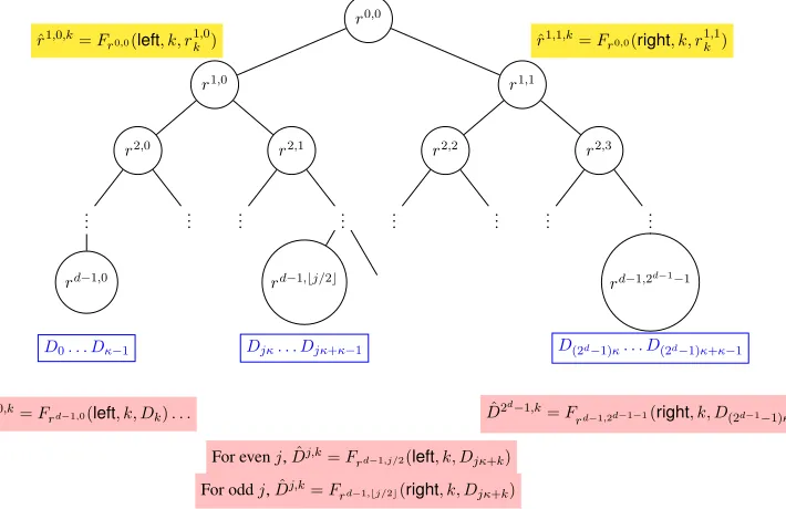
Here is how our memory is garbled: we sample a tree of fresh random keys si,j ∈ {0,1}κ where i ∈ {0, . . . d−1} andj ∈ {0, . . .2i −1} where d = log(m/κ) andm is the size of the database D. The garbled memory itself consists of encryptions of the data under the leaf keys from the key tree and the encryption of each key in the key tree under its parent key. We refer the reader to look at Figure1for a graphical representation of the same. Note that given the root keys0,0, starting from the root, one can navigate the tree and reach any leaf keysd−1,j withd−1decryptions, which can be then used to read the desired bit from memory. On the other hand, withholding the root key, renders the entire tree hidden.
As already pointed, having access to the root key enables reading any bit from memory, and this process involves reading a sequence ofd−1keys from memory. Our idea of key evolution is that in the process of reading a bit from memory we will expunge all the keys along the path from the root to the leaf and replace them with freshly sampled keys. Note that since each key only encrypts two other keys or2κbits of memory, it is easy to read those values and output additionally an encryption of these values under the updated key. In other words, as a circuit navigates the tree, it will update all the nodes visited along the path using fresh keys. The additional subtlety here is that, whenever we replace a node with fresh key, then both its children nodes need to be re-encrypted under the fresh key. We believe that this is a novel approach on tree-based constructions in cryptography, e.g. it differs drastically from statistical ORAM [Ajt10,DMN11, SvDS+13, CP13], Merkle trees [Mer87], GGM PRF [GGM84] and broadcast encryption [FN93] and we expect this to have other applications in cryptography.
Now we explain how this key evolution process solves the circularity problem. We note that at any point in time, any key that is ever used to read any other key or data from memory has already been expunged. This allows us to claim the invariant that at point of time the evolved key tree only consists of pristine keys, that have never been used to read anything from memory. This gives the guarantee that future time steps have essentially nothing to do with the keys that were actively used in previous time steps.1
Finally note that the key evolution only changes the keys in the system but the size of the garbled memory itself does not change. Hence our solution only requirespoly(κ)overhead to store the garbed tree andpoly(κ,logm)additional overhead in the running time of the CPU circuit, required to navigate the tree achieving the desired efficiency goals.
1
We note that in the proof various additional subtleties arise. In the life time of a key it might be read and re-encrypted multiple times, depending on the execution path of the program. The invariant above only claims that the key itself was not used to read anything from memory or in other words PRF values were not computed using this key. In the proof before we can rely on the security of PRF for this key we need to replace all the encryptions of this key with encryptions of random strings. We prove that this can indeed be done as all those encryptions are under keys that have already been expunged and so on.
Writing. Unlike previous GRAM schemes, where writing was more involved, our construction achieves writes in a very simple manner. Recall that reading in our scheme already involved re-encrypting the read data under its new parent. Writing just involves encrypting the value to be written instead of doing the re-encryption.
Decoupling of data garbling and program garbling. A very nice feature of our construction, that enables for various novel applications, is that the only connection between the garbled memory and the garbled program is in terms of the root key which can be fed into the garbled program rather than being hardcoded in it. This means that we can garble the program independent of the data.
2.1 Roadmap
We now lay out a roadmap for the remainder of the paper. In Section3, we give necessary background and definitions for the RAM model, garbled circuits, and garbled RAM. In Section4we give the main con-struction of our result, and prove the security in Section5. We survey other related work in AppendixA. We review oblivious RAM in Appendix B. In Appendix C we give a warmup construction of fully se-cure single-program GRAM from UMA-sese-cure single-program GRAM (such a proof was previously given in [GHL+14], but given our slightly stronger definitions, we re-prove the result under these stronger con-ditions). In Appendix D we show how to obtain fully secure multi-program GRAM from UMA-secure multi-program GRAM.
3
Background
In this section we fix notation for RAM computation and provide formal definitions for Garbled Circuits and Garbled RAM Programs. Parts of this section have been taken verbatim from [GHL+14].
3.1 RAM Model
Notation for RAM Computation. We start by fixing the notation for describing standard RAM com-putation. For a programP with memory of sizem we denote the initial contents of the memory data by
D ∈ {0,1}m. Additionally, the program gets a “short” inputx ∈ {0,1}n, which we alternatively think of
as the initial state of the program. We use the notationPD(x)to denote the execution of programP with initial memory contentsDand inputx. The program canP read from and and write to various locations in memoryDthroughout its execution.2
We will also consider the case where several different programs are executed sequentially and the mem-ory persists between executions. We denote this process as(y1, . . . , y`) = (P1(x1), . . . , P`(x`))D to
indi-cate that firstP1D(x1)is executed, resulting in some memory contentsD1 and outputy1, thenP2D1(x2)is executed resulting in some memory contentsD2and outputy2etc. As an example, imagine thatDis a huge database and the programsPi are database queries that can read and possibly write to the database and are parameterized by some valuesxi.
CPU-Step Circuit. Consider a RAM program who execution involves at mostT CPU steps. We represent a RAM programP via a sequence ofT smallCPU-Step Circuitwhere each of them executes a single CPU
2In general, the distinction between what to include in the programP, the memory dataDand the short inputxcan be somewhat
step. In this work we will denote one CPU step by:
CCPUP (state, zread) = (state0, L, zwrite).
This circuit takes as input the current CPU statestateand a blockzread. Looking ahead this block will be read from the memory location that was requested for a memory location requested for in the previous CPU step. The CPU step outputs an updated statestate0, the next location to readL∈[m], and a blockzwriteto write into the location that was previously read. The sequence of locations and read/write values collectively form what is known as theaccess pattern, namelyMemAccess={(Lτ, zread,τ, zwrite,τ) :τ = 1, . . . , t}.
Note that in the description above without loss of generality we have made some simplifying assump-tions. First, we assume that the outputzwrite is written into the same location zread was read from. Note that this is sufficient to both read from and write to arbitrary memory locations. Secondly we note that we assume that each CPU-step circuit always reads from and write some location in memory. This is easy to implement via a dummy read and write step. Finally, we assume that the instructions of the program itself is hardwired into the CPU-step circuits, and the program can first load itself into memory before execution. In cases where the size of the program vastly differs from its running time, one can suitably partition the program into two pieces.
Representing RAM computation by CPU-Step Circuits. The computationPD(x)starts with the initial state set as state0 = x and initial read location L0 = 0 as a dummy read operation. In each stepτ ∈
{0, . . . T −1}, the computation proceeds by first reading memory locationLτ, that is by settingbread,τ :=
D[Lτ]ifτ ∈ {1, . . . T−1}and as0ifτ = 0. Next it executes the CPU-Step CircuitCCPUP (stateτ, bread,τ) = (stateτ+1, Lτ+1, bwrite,τ+1). Finally we write to the locationLτby settingD[Lτ] :=bwrite,τ+1. Ifτ =T−1 then we set stateto be the output of the program P and ignore the valueLτ+1. Note here that we have without loss of generality assumed that in one step the CPU-Step the same location in memory is read from and written to. This has been done for the sake of simplifying exposition.
3.2 Garbled Circuits
Garbled circuits was first constructed by Yao [Yao82] (see Lindell and Pinkas [LP09] and Bellare et al. [BHR12] for a detailed proof and further discussion). A circuit garbling scheme is a tuple of PPT algorithms(GCircuit,Eval). Very roughlyGCircuit is the circuit garbling procedure and Evalthe corresponding evaluation procedure. Looking ahead, each individual wirewof the circuit will be associated with two labels, namelylabw0,labw1. Finally, since one can apply a generic transformation (see, e.g. [AIK10]) to blind the output, we allow output wires to also have arbitrary labels associated with them. Indeed, we can classify the output values into two categories —plain outputsandlabeled outputs. The difference in the two categories stems from how they will be treated when garbled during garbling and evaluation. The plain output values do not require labels provided for them and evaluate to cleartext values. On the other hand labeled output values will require that additional output labels be provided toGCircuitat the time of garbling, andEvalwill only return these output labels and not the underlying cleartext. We also define a well-formedness test for labels which we callTest.
• C,˜ {(w, b,labwb )}w∈inp(C),b∈{0,1}←GCircuit 1κ, C,{(w, b,labwb)}w∈out(C),b∈{0,1}
:GCircuittakes
as input a security parameterκ, a circuitC, and a set of labelslabwb for all the output wiresw∈out(C) andb∈ {0,1}. We denote the set of input and output wires byinp(C)andout(C)respectively. This procedure outputs agarbled circuitC˜ and a set of labelslabwb for each input wirew ∈ inp(C)and
b∈ {0,1}.
• {(w, ow)}w∈out(C)
=Eval( ˜C,{(w,labwxw)}w∈inp(C)): Given a garbled circuitC˜ and a sequence of input labels{(w,labwxw)}w∈inp(C),Evaloutputs a sequence of outputs{(w, o)}w∈out(C), where each
owis eitheryworlabwyw depending on whether the output is being given in the clear or as a label only.
Correctness. For correctness, we require that for any circuitCand inputx∈ {0,1}n(herenis the input length toC) we have that that:
Prh {(w, yw,labwyw)}w∈out(C)
=Eval( ˜C,{(w,labwxw)}w∈inp(C))i= 1
where
˜
C,{(w, b,labwb )}w∈inp(C),b∈{0,1}
←GCircuit 1κ, C,{(w, b,labw
b)}w∈out(C),b∈{0,1}
andy=C(x). We require that the testing algorithm works correctly:Test(lab) = 1if(·,·,lab)∈ {(w, b,labwb)}w∈inp(C),b∈{0,1}, where
˜
C,{(w, b,labwb )}w∈inp(C),b∈{0,1}
←GCircuit 1κ, C,{(w, b,labwb)}w∈out(C),b∈{0,1}
, andPr[Test(r) = 1]is negligible whenr is uniform. This can be implemented, for example, by enforcing all labels have a
O(k)-size padding of 0 bits.
Security. For security, we require that there is a PPT simulator Simsuch that for any C, x,and labels
{(w, b,labwb)}w∈out(C),b∈{0,1}
, we have that:
˜
C,{(w,labwxw)}w∈inp(C)
comp
≈ Sim 1κ,{(w, b,labwyw)}w∈out(C)
whereC,˜ {(w, b,labwb )}w∈inp(C),b∈{0,1}←GCircuit 1κ, C,{(wlabwb)}w∈out(C),b∈{0,1}
andy=C(x).
3.3 Garbled RAM
Next we consider an extension of garbled circuits to the setting of RAM programs. In this setting the memory dataDis garbled once and then many different garbled programs can be executed sequentially with the memory changes persisting from one execution to the next. We will start by presenting our definitions for the case when only one program is garbled and then present the definitions for the case when multiple programs are garbled in the Appendix. Another simplifying assumption we make is that in our definition here, we focus on a weaker variant (that also appeared in [GHL+14]) known as Unprotected Memory Access (UMA) , and we define full security in the Appendix and show how UMA-secure Garbled RAM can be compiled with Oblivious RAM to achieve full security.
Syntax. AUMA-secure single-program garbled RAMscheme consists of four procedures:(GData,GProg, GInput,GEval)with the following syntax:
• ( ˜D, s) ← GData(1κ, D): Given a security parameter1κ and memoryD∈ {0,1}m as inputGData
outputs the garbled memoryD˜.
• ( ˜P , sin)←GProg(1κ,1logm,1t, P): Takes the description of a RAM programP with memory-size
mas input. It then outputs a garbled programP˜and an input-garbling-keysin.
• x˜ ← GInput(1κ, x, sin, s): Takes as inputx ∈ {0,1}n
and and an input-garbling-keysin, a garbled
“tree root” keysand outputs a garbled-inputx˜.
• y = GEvalD˜( ˜P ,x˜): Takes a garbled programP˜, garbled inputx˜ and garbled memory data D˜ and output a value y. We model GEval itself as a RAM program that can read and write to arbitrary locations of its memory initially containingD˜.
Correctness. For correctness, we require that for any programP, initial memory dataD ∈ {0,1}mand inputxwe have that:
Pr[GEvalD˜( ˜P ,x˜) =PD(x)] = 1
where( ˜D, s)←GData(1κ, D),( ˜P , sin)←GProg(1κ,1logm,1t, P),x˜←GInput(1κ, x, sin, s).
Security with Unprotected Memory Access (UMA). For security, we require that there exists a PPT simulatorSimsuch that for any programP, initial memory dataD ∈ {0,1}mand inputx, which induces access patternMemAccesswe have that:
( ˜D,P ,˜ x˜)comp≈ Sim(1κ,1m,1t, y, D,MemAccess)
where
( ˜D, s) ← GData(1κ, D), ( ˜P , sin) ← GProg(1κ,1logm,1t, P) and x˜ ← GInput(1κ, x, sin, s), and
y=PD(x).
4
The Construction
In this section we describe our construction for garbled RAM formally, namely the procedures (GData, GProg,GInput,GEval). We use the notation[n]to denote the set{0, . . . , n−1}. Throughout the construc-tion, we letF : {0,1}∗ → {0,1}κ be a PRF with seed lengthκ. For any stringx we reserve the use of subscript to denote its bit locations. For example for a stringx, we usexi to denote theith bit ofxwhere
i∈[|x|]with the0thbit being the highest order bit.
r0,0
r1,0
r2,0
.. .
rd−1,0
.. .
r2,1
..
. ...
rd−1,bj/2c
r1,1
r2,2
..
. ...
r2,3
..
. ...
rd−1,2d−1−1
D0. . . Dκ−1 Djκ. . . Djκ+κ−1 D(2d−1)κ. . . D(2d−1)κ+κ−1
ˆ
r1,1,k=Fr0,0(right, k, r
1,1
k )
ˆ
r1,0,k=Fr0,0(left, k, r
1,0
k )
ˆ D0,k=F
rd−1,0(left, k, Dk). . .
For evenj,Dˆj,k=F
rd−1,j/2(left, k, Djκ+k)
For oddj,Dˆj,k=Frd−1,bj/2c(right, k, Djκ+k)
ˆ
D2d−1,k=F
rd−1,2d−1−1(right, k, D(2d−1−1)κ+k)
Figure 1:Visualization of Memory Garbling.
4.1 Data Garbling: ( ˜D, s)←GData(1κ, D)
In the figure these keys are shown on in the black circles. Note that at the lowest key the tree consists of 2d−1 keys. These keys are what are used to encrypt the data. In particular for any evenj ∈ [2d], a total of2κ bits ofD, namelyDjκ. . . Djκ+2κ−1 are encrypted using the key rd−1,j/2. The firstκ of these are encrypted with a tagleftand the nextκones are encrypted with the tagright. For example in Figure1we show the encryption of firstκbits of D, the lastκbits of Dandjκtojκ+κ−1bits of D, under keys
rd−1,0,rd−1,2d−1−1andrd−1,bj/2crespectively. These encryptions are colored in pink.
TheGData(1κ, D)procedure proceeds as follows.
1. Sample{ri,j}
i∈[d],j∈[2i]← {0,1}κ.
2. Without loss of generality we assume thatm = 2d·κwheredis a positive integer and setm0 = 2d. For j ∈ [m0]andk ∈ [κ], ifj mod 2 = 0set Dˆj,k = Frd−1,j/2(left, k, Djκ+k) else set Dˆj,k =
Frd−1,bj/2c(right, k, Djκ+k), whereDjκ+kdenotes thejκ+kthbit ofD.
3. ∀i∈ {1, . . . d−1}, j ∈ [2i], k ∈[κ], ifj mod 2 = 0then computerˆi,j,k =Fri−1,bj/2c(left, k, ri,jk )
else computeˆri,j,k=Fri−1,bj/2c(right, k, rki,j), whereri,jk denotes thekthbit ofri,j.
4. OutputD˜ = ({ˆri,j,k}i∈[d]\{0},j∈[2i],k∈[κ],{Dˆj,k}j∈[2d],k∈[κ])ands=r0,0.
Figure 2:Formal description ofGData.
We also generate encryptions of each key in the tree under its parent. Specifically, each bit of the keyri,j
is encrypted under the keyri−1,bj/2c. For example in Figure1we provide encryptions ofr1,0andr1,1under
r0,0 in yellow color. The garbled memory provided consists of the generated encryptions of the provided keys and the memory.
4.2 Program Garbling: ( ˜P , sin)←GProg(1κ,1logm,1t, P)
We start by defining three sub-circuits and some notation that will be needed in describing the garbling itself.
Our Sub-Circuits. We use the notationCtype[param]to describe a circuitCtype that has hardwired
pa-rametersparam, wheretype ∈ {nav,step,final}the three types of circuits we will define. These circuits will be referred to as thenavigationcircuit, thestepcircuit and thefinalcircuit respectively.
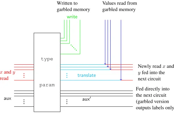
write
Written to garbled memory
Values read from garbled memory
Newly readxand yfed into the next circuit
aux aux0
Fed directly into the next circuit (garbled version outputs labels only) xandy
read translate
param type
Input-output behavior of these circuits. Each one of these three circuits takes as input (x, y,aux), where
x, y∈ {0,1}κandaux= (state, L)wherestate∈ {0,1}∗andL∈ {0,1}d. Looking ahead,x, ydenote the 2κbits just read from garbled memory, staterepresents the input state of the CPU computation including locationLthat describes the block of data memory we are currently interested in reading.
1. Navigation CircuitCnav[r, r0, i,lab]: This circuit has hardwired in it PRF keysrandr0, valuei∈[d] and labels lab = {lableft,k,b,labright,k,b}k∈[k],b∈{0,1}. On inputx, y ∈ {0,1}κ, aux = (state, L) ∈ {0,1}∗× {0,1}dthe circuit output is generated as follows.
(a) IfLi = 0then setkey =x, newL=r0, newR =yelse setkey=y, newL=x, newR=r0
and setwrite:= (L,{Fr(left, k, newLk), Fr(right, k, newRk)}k∈[κ]),
translate:=
(
Fkey(left, k,0)⊕lableft,k,0, Fkey(right, k,0)⊕labright,k,0,
Fkey(left, k,1)⊕lableft,k,1, Fkey(right, k,1)⊕labright,k,1. )
k∈[κ]
(b) Randomly permute the rows oftranslateand output(write,translate,aux).
2. Step Circuit Cstep[r, s,lab]: This circuit has hardwired in it PRF keysr and sand labels lab =
{lableft,k,b,labright,k,b }k∈[k],b∈{0,1}. On inputx, y ∈ {0,1}κ,aux = (state, L) ∈ {0,1}∗× {0,1}d
the circuit output is generated as follows.
(a) Set newL = x, newR = y. If Ld−1 = 0 then set read = x else read = y. Compute (state0, L0, z) := CCPUP (state, read). If Ld−1 = 0 then overwritenewL = z else overwrite
newR=z.
(b) Computewrite:= (L0,{Fr(left, k, newLk), Fr(right, k, newRk)}k∈[κ]),
translate:=
(
Fs(left, k,0)⊕lableft,k,0, Fs(right, k,0)⊕labright,k,0,
Fs(left, k,1)⊕lableft,k,1, Fs(right, k,1)⊕labright,k,1. )
k∈[κ]
(c) Randomly permute the rows of translate and output (write,translate,aux0) where aux0 := (state0, L0).
3. Final CircuitCfinal[r]: This circuit is similar to the circuitCstep[r, s]but with part of its functionality trimmed. This circuit has hardwired in it PRF keysr. On inputx, y ∈ {0,1}κ,aux = (state, L) ∈ {0,1}∗× {0,1}dthe circuit output is generated as follows.
(a) Set newL = x, newR = y. If Ld−1 = 0 then set read = x else read = y. Compute (state0, L0, z) := CP
CPU(state, read). If Ld−1 = 0 then overwritenewL = z else overwrite
newR=z. Computewrite:= (L0,{Fr(left, k, newLk), Fr(right, k, newRk)}k∈[κ]). (b) Output(write,aux0)whereaux0:= (state0, L0).
Figure 4:Formal description of subcircuits forGProg.
(write,aux). Note that the final circuit is essentially same as the step circuit except the functionality that generatestranslatehas been trimmed. This is depicted in Figure3.
Communication between different circuits. Looking ahead, our garbling of a RAM program will consist of garbling of multiple copies of these three circuits instantiated with different parameters hardwired into them. Furthermore we will need this garbling to be such that these garbled circuits can “talk to each other.” This communication will be enabled in two ways: 1) We directly pass the output of one circuit into the input of another. This can be achieved by having the first garbled circuit produce as output the labels needed for the inputs of the next garbled circuit. 2) The garbled memory is involved, where in particular, one garbled circuit will output a translation table which will encode pairs of labels for input wires of the second circuit it wants to communicate with. Given this translation table depending on bits stored in the garbled memory the evaluator will be able to obtain exactly 1-out-of-2 of the labels. This will be tantamount to reading from the underlying memory. The translation information corresponds precisely to the translate output of the navigation and the step circuits. More specifically, let lab = {lableft,k,b,labright,k,b}k∈[κ],b∈{0,1} be
the labels for input wires of a circuit with which the circuit at hand is trying to communicate. Since the translation tabletranslategenerated by the circuit at hand needs to depend on the labelslab, we will need to hard-code these labels in the circuit being garbled.
We detail the subcircuits in Figure 4. The process of garbling multiple instances of these circuits and their process of communication will be explained later.
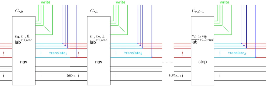
The actual garbling. We now provide an informal description of our RAM garbling procedure. A formal description ofGProgis provided in Figure6.
As mentioned earlier, garbling a RAM program will involve garbling multiple instances of circuits described earlier. Specifically if the running time of the programP being garbled istand the size of the database ism=m0·κ, then the garbled RAM program will consist oft·logm0garbled circuits which we can intuitively group intologm0 garbled circuits for each time step of the program. In particular for each time step we will consider a sequence oflogm0−1instances ofCnavfollowed by one instance ofCstep. For the last time step we just replace the lastCstepcircuit withCfinal. Recall that the only difference between
CstepandCfinalis that unlikeCstep,Cfinaldoes not output any translate informationtranslate.
Now that we have explained the overall structure, we will next describe the role of each of these circuits. It is helpful to keep in mind how the garbled memory is constructed using a tree of keys (cf. Fig2). In short, theplainversion simply consists of a tree of randomly sampled PRF keys for each non-leaf node, and aκbit data block from databaseDfor each leaf. Theencryptedversion of this plain version, which constitutes the actual garbled memory, consists of an encryption of each PRF key under its parent, with the root removed. More specifically, a non-root PRF key (or a database block)ris encrypted as{Fs(left/right, k, rk)}k∈[κ], whereleft/rightindicates if the node is a left or right child,sis the PRF key of its parent, andrkis thekth
bit of the PRF key (or the database block).
For each step τ ∈ [t] of the computation, the step circuit Cstep requires a κ-bit block of data from memory at locationL. However this is encrypted under a key from leveld−1. This key is itself encrypted under another key from leveld−2 and so on. Hence in order to read the desired memory location, we need to navigate in the memory from level0to leveld−1reading one key at a time and finally recovering the desired data block. This is exactly what will be achieved by a sequence oflogm0 circuits. As we will see next the last of these circuits also performs the computation corresponding to the time step and help kick-start the next computation step. This depicted informally in Figure5.
write
aux0
˜ Cτ,0
translate1
nav
v0, v1,0,
labτ,1,read
write
aux1
˜ Cτ,1
translate2
nav
v1, v2,1,
labτ,2,read
write
auxd−1
˜ Cτ,d−1
translated
step
vd−1, v0,
labτ+1,0,read
Figure 5:Visualization of one time step of the RAM Program.
and this would enable it to read the two children of the root needed for the nextlogm0 sequence of garbled circuits needed for the next time step. Additionally for security, each step will also replace each key along the path that has been used to decrypt anything else with a fresh key. The reason for this is that for security we maintain the variant that any PRF key in the system is used at most once for reading anything. So any time a PRF key is used to decrypt its two children then then that PRF key is immediately updated to fresh key.More details on why this is needed will be elaborated on in the proof.
A bit more precisely, we consider the semantics ofCnav[r, r0, i,lab](x, y,aux)which will output(write, translate,aux). Herer0 is a freshly chosen PRF key that will replace either the plain value of the one of the two PRF keys it gets as input, depending on the path we do end up taking, which in turn depends on the memory block we are interested in reading. The PRF keyr is the PRF key that replaced the PRF key of the parent of the two nodes in consideration. Since the key of the parent has been updated we need to to re-encrypt the input PRF keys underr. At a high level, in reading some data locationLwe replace all the keys, along the path in the tree from the root to the leaf, with fresh PRF keys. For consistency this requires that the children of all these nodes corresponding to which keys have have updated be re-encrypted under these fresh keys. Interestingly this includes the siblings that haven’t even been used. We stress that even though a priori we do not not know which values in key tree will be replaced with fresh values; we do know that the values they will be replaced with (they are freshly chosen) and these values are what are hardwired into the circuits.
Finally, we describe the other two circuitsCstepandCfinal in terms of how they differ fromCnav a bit more. These circuits can be considered as virtual navigate circuits at leveld−1: the input consist of two leaf nodes which correspond to actual memory that can be read from, and it helps in enabling “wrap around.” In other words a mechanism that enables reading the PRF keys stored in the two children of the root node. Also, unlikeCnavwhich replaces each key used to read other keys with a fresh key, this circuit executes the underlying CPU step and writes back the blockbwrite. Finally, in order to obtain the translation table, these circuits will be hardwired with the value of the root node. Note that Cfinal is same asCstep except that it does not need to provide any “wrap around.”
Now that we have roughly described the overall structure and the role of each individual circuit in the garbling process we will next describe a bit more precisely how the garbled circuits communicate. This is actually very simple. Each circuitC˜τ,ipasses on its outputauxdirectly as input to the circuitC˜τ,i+1 if
i < d−1or to the circuitC˜i+1,0otherwise. Similarly the circuitC˜τ,iprovides translation information that enables evaluator of these garbled circuits to read a bit from memory.
Toward capturing this, we use the following notation. We denote the set ofallinput labels of circuitC˜τ,i
wherelabτ,i,readdenotes the input labels corresponding to the input valuesxandy — the values justread
from memory andlabτ,i,auxdenotes the input labels corresponding to the inputaux. Generating the garbled circuitC˜τ,i+1requires additionally the informationlabτ,i+1ifi < d−1andlabτ+1,0otherwise.
We note that since the generation ofC˜τ,i+1depends on labelslabτ,i+1orlabτ+1,0, therefore we need to gable these circuits in the opposite order, i.e. garbling the last circuit first. As a result, during garbling we will know ahead of time what the input labels for the next garbled circuit will be.
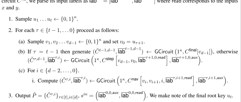
TheGProg(1κ,1logm,1t, P)procedure proceeds as follows. All garbled sub-circuits will outputwriteand
translatein the clear, so we omit assigning wire labels to them when invokingGCircuit. Given a garbled circuitC˜τ,i, we parse its input labels aslabτ,i = [labτ,i,read,labτ,i,aux]wherereadcorresponds to the inputs
xandy.
1. Sampleu1. . . ut← {0,1}κ.
2. For eachτ ∈ {t−1, . . .0}proceed as follows:
(a) Samplev1, v2. . . vd−1 ← {0,1}κand setv0 =uτ+1.
(b) If τ = t−1 then generate ( ˜Ct−1,d−1,labt−1,d−1) ← GCircuit 1κ, Cfinal[vd−1]
, otherwise
( ˜Cτ,d−1,labτ,i)←GCircuit
1κ, Cstep h
vd−1, v0,lab
τ+1,0,readi
,labτ+1,0,aux
.
(c) Fori∈ {d−2, . . . ,0}.
i. Compute( ˜Cτ,i,labτ,i)←GCircuit
1κ, Cnav h
vi, vi+1, i,lab
τ,i+1,readi
,labτ,i+1,aux.
3. OutputP˜ ={C˜τ,i}τ∈[t],i∈[d],sin=lab0,0,aux,lab0,0,read. We make note of the final root keyut.
Figure 6:Formal description ofGProg.
4.3 Input Garbling: x˜←GInput(1κ, x, sin, s)
Informally, theGInputalgorithm usesxandsas selection bits for the labels provided bysinand outputsx˜, which is just the selected labels. A formal description ofGProgis provided in Figure7.
The algorithmGInput(1κ, x, sin, s)proceeds as follows. Heresin= (labaux,labread).
1. Parselabreadas{lableft,k,b,labright,k,b}k∈[κ], b∈ {0,1}and compute
translate:=
(
Fs(left, k,0)⊕lableft,k,0, Fs(right, k,0)⊕labright,k,0,
Fs(left, k,1)⊕lableft,k,1, Fs(right, k,1)⊕labright,k,1. )
k∈[κ]
2. Output (translate,labc
aux,state=x,L=0
), where labc
aux,state=x,L=0
selects the wire labels for aux =
(state, L) as labc
aux,state=x,L=0
= {labaux,i,xi}i∈inp(state),{labaux,i,0}i∈inp(L), where these are se-lected from the full set of labelslabaux={labaux,i,b}i∈inp(aux)=inp(state,L),b∈{0,1}.
4.4 Garbled Evaluation: y←GEvalD˜( ˜P ,x˜)
TheGEvalprocedure gets as input the garbled databaseD˜is({rˆi,j,k}i∈[d−1]\{0},j∈[2i],k∈[κ],{Dˆj,k}j∈[2d],k∈[κ]),
the garbled programP˜ ={C˜τ,i}
τ∈[t],i∈[d]and the garbled inputx˜ = (translatex,labc
aux,x
). Intuitively the
GEvalis very simple. It proceeds by executing the sequence of garbled programs in the prescribed order. The labels needed to evaluate the first garbled circuit are provided as part of the garbled input and each evaluation of a garbled circuit reveals the labels needed for the next circuit. Evaluation of each garbled cir-cuit also generates additional values for writing into memory and translation tables for reading values from memory. These are also carried out in the natural manner. Next we provide the formal descriptionGEval. We will define a functionDeTranslate(translate,{ˆrleft,k,ˆrright,k}k∈[κ],C˜)that unblinds the labels one at a time. The functionDeTranslateinterprets
translate=
(
αleft,k,0,αright,k,0
αleft,k,1,αright,k,1 )
and outputs labels {βleft,k, βright,k}
k∈[κ]computed as follows: For each input wirexi corresponding tox,
for b ∈ {0,1}if Test( ˜C,(xi, b, αleft,k,b ⊕ˆrleft,k)) = 1 then setβleft,k = αleft,k,b ⊕ˆrleft,k. Similarly, for
each input wireyi corresponding toy, for b ∈ {0,1}if Test( ˜C,(yi, b, αright,k,b⊕ˆrright,k)) = 1then set
βright,k=αright,k,b⊕ˆrright,k. A formal description ofGProgis provided in Figure8.
The algorithmGEvalD˜( ˜P ,x˜)proceeds as follows.
1. InitializeL= 0,translate:=translatexandlabc :=labc
aux,x
.
2. Forτ ∈[t],i∈[d−1]do:
(a) Letlbe the number obtained by considering theihigher order bits ofL, setting it to0ifi= 0.
(b) Execute(write0,translate0,labc 0
) :=Eval( ˜Cτ,i,(DeTranslate(translate,{rˆi+1,2l,k,
ˆ
ri+1,2l+1,k }k∈[κ]),labc)).
(c) Parsewrite0 as(L0,{αleft,k, αright,k}
k∈[κ])and for everyk∈[κ]ifi < d−1updateri+1,2l,k :=
αleft,kandri+1,2l+1,k :=αright,k else updateD˜2l,k :=αleft,kandD˜2l+1,k:=αright,k.
(d) UpdateL=L0,translate:=translate0 andlabc :=labc 0
.
Figure 8:Formal description ofGEval.
5
Security Proof
In this section we prove the UMA-security of the garbled RAM(GData,GProg,GInput,GEval)shown in Sec.4.
Theorem 5.1(UMA-security). Given any OWF and a secure garbling scheme (which can be built from the OWF), our construction is a UMA (unprotected memory access) secure garbled RAM scheme.
An extension of this theorem provided in LemmaD.1along with TheoremD.2allows us to immediately obtain the following corollary.
Proof Sketch:We now sketch a proof of Theorem5.1to give intuition, and then we provide the full proof. We construct a simulator Sim that produces simulated garbled circuits starting from the last circuit. It proceeds by generating a random-looking output for eachC˜τ,i by settingtranslateto be a random key
XORed with the corresponding input labels ofC˜τ,i+1 (since we are working backwards, these labels have already been generated), and similarly using random values forwrite. The main idea is that we perform bookkeeping to keep track of these random values, so that when we simulate the garbled database, we setD˜
to be uniformly random subject to matching the bookkeeping: since the UMA-simulator gets the full access pattern, it knows exactly which locations in memory it should set entries so that they match what was used to mask the translation table.
Then in order to argue that the simulated output is indistinguishable from the real distribution, we define a sequence of hybridsH0,0, H0,1, . . . , H0,d−1, H1,0, . . . , Ht−1,d−1 that replaces circuits from the first cir-cuit onward, where inHτ,i, the circuitsC˜τ0,i0 have been simulated for all(τ0, i0)<(τ, i)lexicographically.
Moving toHτ,ifromHτ,i−1(and analogously toHτ,0fromHτ−1,d−1), we carefully define subhybridsHprfτ,i,
Hencτ,i, andHcircuitτ,i , where we first argue that the PRF outputs can be replaced, followed by replacing the
la-bels that won’t be decrypted intranslate, followed by simulating the circuit now that the dependencies on the unopened labels have been removed.
Proof:
Simulator. Under UMA-security, Sim gets the inputs1κ,1m,1t, y, D and MemAccess= {(Lτ, zread,τ,
zwrite,τ) :τ = 1, . . . , t}, where programP executestCPU steps and outputsy, the initial memory contents areD∈ {0,1}mandMemAccessdescribes the entire memory access throughout alltCPU steps executed.
Overview. The simulatorSimcomputes the garbled circuits from the last circuit. It uses the knowledge
MemAccessto compute the output of each garbled circuit and the nodes that will be visited at each step.
Simcomputes everyC˜τ,iby first computing its output: translate,write,state. The tabletranslate con-sists of random keys xored with the input labels of C˜τ,i+1 (which are available when computing C˜τ,i as
˜
Cτ,i+1has been already computed). Such keys are kept in a global fileF as they represent the nodes of the memory in a previous step: they will be either used as the outputwriteof some circuitC˜τ0,i−1 for some
τ0 < τ, or if no other circuit has visited this node before, they will be part of the garbled data given in input at the beginning.
Notation. Recall that labτ,i = [labτ,i,read,labτ,i,aux]and that for a circuit C˜i,j, labread = {lableft,k,b,
labright,k,b}k∈[κ],b∈{0,1}. In the description of the simulator, we abuse the notation and we uselabτ,i for the keys obtained from the simulator of the garbled circuits. The set setlabτ,igenerated byCircSimwill contain only one key per wire.
We use notation ˆri+1,2l,k{τ}the garbled valueˆrj+1,2l,k at stepτ. The simulator uses auxiliary proce-duresGenerateWriteshown if Fig.10andGenerateTranslateshown in Fig.9.
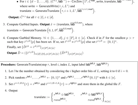
Procedure Simulator:Sim(1κ,1m,1t, y, D,MemAccess={Lτ, zread,τ, zwrite,τ}
τ=1,...,t)
1. Initialize a fileFto store the nodes of the garbled memory visited during the simulated execution.
2. Compute Garbled Circuits.
For each stepτ ∈ {t−1, . . . ,0}do.
• Ifτ =t−1. ( ˜Ct−1,d−1,labt−1,d−1)←CircSim 1κ, Cfinal,write,aux
whereaux= (y, Lt−1);write= (GenerateWrite(t−1, d−1, Lt−1), zwrite,t−1).
Else,( ˜Cτ,d−1,labτ,d−1)←CircSim
1κ, Cstep,write,translate,labτ+1,0,auxwhere
write=GenerateWrite(τ, d−1, Lτ)and
• Fori∈ {d−2, . . . ,0}. ( ˜Cτ,i,labτ,i)←CircSim1κ, Cnav,write,translate,labτ,i+1,aux,
wherewrite=GenerateWrite(τ, i, Lτ)and
translate=GenerateTranslateτ, i+ 1, Lτ,labτ,i+1,read.
Output: C˜τ,ifor allτ ∈[t], i∈[d].
3. Compute Garbled Inputs. Outputx˜= (translate,lab0,0,aux), where
translate=GenerateTranslate0,1,0d,lab0,0,read.
4. Compute Garbled Memory. ∀i∈ {1, . . . d}, j ∈[2i], k ∈[κ]. Check if inF for the smallestp > τ
such that keyˆri,j,k{p}has been set. If so, setˆri,j,k=ˆri,j,k{p}else setˆri,j,k← {0,1}κ.
Finally, set{Dˆj,k = ˆrd,j,k}j∈[2d],k∈[κ].
OutputD˜ = ({ˆri,j,k}i∈[d]\{0},j∈[2i],k∈[κ],{Dˆj,k}j∈[2d],k∈[κ])
Procedure:GenerateTranslate(stepτ, leveli, indexL, input labellableft,k,labright,k)
1. Letlbe the number obtained by considering theihigher order bits ofL, setting it to0ifi= 0.
2. Pick randomrleft,1, . . . , rleft,k ← {0,1}κandrright,1, . . . , rright,k{0,1}κwithk∈[κ].
3. Setˆri+1,2l,k{τ}=rleft,k andrˆi+1,2l+1,k{τ}=rright,kand store them in the global fileF.
4. Output
translate:=
(
rleft,k⊕lableft,k, rleft,k⊕labright,k
randleft,k, randright,k.
)
k∈[κ]
whererandright,k andrandleft,kare randomly chosen. The rows oftranslateare randomly permuted.
Figure 9:ProcedureGenerateTranslate.
Procedure:GenerateWrite(stepτ, leveli, indexL)
1. Letlbe the number obtained by considering theihigher order bits ofL.
2. Look up in F for the smallest timestamp p > τ for which nodes ˆri+1,2l,k{p} andˆri+1,2l+1,k{p}
withk ∈[κ]have been already computed. If suchpexists setαleft,k := ri+1,2l,k{p}andαright,k :=
ri+1,2l+1,k{p}. (suchpexists if in a later steppa translate table was computed to read nodes(i+1,2l) and(i+ 1,2l+ 1). Else, setαleft,k ← {0,1}κandαright,k ← {0,1}κwithk∈[κ].
3. Output(L,{αleft,k, αright,k} k∈[κ]).
Figure 10:ProcedureGenerateWrite.
In the garbled memory a node at level i, is computed under some PRF key v and encodes two keys
vleft, vright, which are the keys used to compute the left and right child respectively. We say that the PRF key
visused, while the PRF keysvleft, vrightareencoded.
During the computation, say at stepτ, circuitC˜τ,i reads the two keys encoded in a node at leveli, say
vleft, vright;usesone of the keys, sayvleft, to computetranslateand updates the node at leveliusing a fresh keyv0. To update a node means to re-encode the keysv00, vright using the fresh PRF keyv0 (in our example we are replacingvleft). The PRF key v00 is replacingvleft and is encoded for the first time in the memory, therefore we say the PRF keyv00was born. Instead, keyvleft, that isusedto computedtranslatetable, at this point is not encoded in the parent anymore and it will be replaced with another key by next circuitC˜τ,i+1. Therefore, we say that once a key is used to computetranslatetable, the key isdeadas it has disappeared from the system.
Keyvrightinstead is re-encoded in the parent node and will be possibly read again in the future. With this notation in hand we are able to formalize the following Lemma.
Lemma 5.3(Life of a PRF key). Part 1. Any PRF keyvis used for evaluation in at most two circuits. Part 2. At the time whenvdies,vis encoded only in nodes computed with keys that are dead already.
Part 1. In any step of computationτ, any PRF keyvhardwired in circuitC˜τ,iis used for PRF evaluation in at most two places:
1. Inside circuitC˜τ,ito compute the outputwrite, which is the updated version of nodes at leveli.
2. Inside circuit C˜τ0,i−1 for some step τ0 > τ to compute the translate table to read a node at leveli. CircuitC˜τ0,i−1reads in inputv, xand usesvto compute the translate table to read the node computed under keyv(specifically, the one that was given in output byC˜τ,i). Also, circuitC˜τ0,i−1 recomputes the parent node, i.e., the node at leveli−1, so that it does not encodev.
This is the last time in which the keyvis used. The next circuitC˜τ,iwill not be aware ofvand it will recompute the node at leveliwith a fresh new key. This prove Part 1 of the lemma.
Part 2. Between timeτ and timeτ0the keyvcould have been read, and re-encoded multiple times in the parent node (following the previous example, the parent node lies at leveli−1).
We know that every time the parent node has been visited (and thusvhas been read) it has been readily recomputed under a fresh key. In particular, whenC˜τ0,i−1reads in inputv, xand it knows thatvis gonna be used next, it re-computes the parent node at leveli−1so that it does not encodevanymore. Therefore, at step(τ0, i−1), the only nodes encoding the keyvare the ones that were computed under dead keys. This proves Part 2 of the Lemma.
Indistinguishability of the simulation. We prove indistinguishability of the simulation through a se-quence of hybrids. Starting from the first circuit, i.e.,C˜0,0, in each hybrid we replace a garbled circuit with a simulated circuit. Along the way we replace the nodes visited by the simulated circuits with random nodes. We say that a pair of nodes(i, j)and(i, j+ 1)isvisitedat stepτ if circuitC˜τ,i−1 outputs a translate table that uses the memory valuesˆri,j,k andrˆi,j+1,k withk ∈[κ]. We say that a node israndom if all the PRF evaluations are replaced with fresh random values.
The rationale behind the hybrids is the following. Let Hτ,i−1 be the experiment where all circuits up toC˜τ,i−1 have been successfully replaced with simulated circuits and the nodes visited by these circuits have been replaced with random nodes. In hybridHτ,iwe aim to replace circuitC˜τ,iwith a simulated one, and claim that the distribution of this experiment is computationally indistinguishable to the distribution of experimentHτ,i−1 by invoking the security of the garbling scheme.
labτ,i,auxandlabτ,i,read. Setlabτ,i,auxis passed directly from circuitC˜τ,i−1, and contains already one label only for each wire. Due to the security of C˜τ,i−1 (which we already replaced with a simulated circuit), the adversary cannot learn the other label. Instead,labτ,i,readare passed viatranslate, and both labels are encrypted intranslateusing a key derived from the PRF used to compute nodes(i, j),(i, j+ 1)(for some nodej).
The core of the argument is to show that we can replacetranslate with a table that encrypts only one label per input wire, by first replacing the PRF keys with randomly generated keys and then replacing one of the input labels with random values. Then we can finally replace circuitC˜τ,iwith a simulated circuit and rely on the security of the garbling scheme. Next, we describe the core hybrid formally.
HybridHτ,i. LetHτ,i−1 withτ = {0, . . . , t−1}andi = {1, . . . , d−1}, be the experiment where all circuits till circuitC˜τ,i−1have been successfully replaced with simulated circuits. The case where we move betweenHτ,0 andHτ−1,d−1 is analogous. In hybridHτ,i we aim to replace circuitC˜τ,i with a simulated one.
Recall that the input labelslabτ,i,readused to evaluate circuitC˜τ,i are encrypted in the table translate
which is given in output by circuitC˜τ,i−1, and are decrypted using the keys stored in nodeˆri,j,k,ˆri,j+1,k, for some nodej. Note that this node was either never visited, in that case the PRF key used to encrypt this node has never been used in any previous circuit, or it was visited in some stepτ0 < τ. In such a case the valueˆri,j,k,ˆri,j+1,kis in the outputwriteof circuitC˜τ0,iwhich at this point has been already replaced with simulated circuit. Recall that the outputs of circuitC˜τ,i−1are:
1. translate table:
translate:=
(
Fri−1,bj/2c(left, k,0)⊕lableft,k,0, Fri−1,j/2(right, k,0)⊕labright,k,0,
Fri−1,bj/2c(left, k,1)⊕lableft,k,1, Fri−1,j/2(right, k,1)⊕labright,k,1.
)
k∈[κ]
wherelabτ,i,read=
lableft,k,b,labright,k,0withb= 0,1. Note thatri−1,bj/2cdies at this step.
2. new node:write=(L,ˆri−1,j,k,ˆri−1,j+1,k}k∈[κ]).
(Note that this node might be used in a later step τ00 > τ (if any), to decrypt the translate table computed by a circuitC˜τ00,i−1, which has not been replaced at this point. Therefore in this hybrid we will not replacewriteyet: we will replace it in hybridHτ00,i.)
Sub-hybridHprfτ,i. Letv =ri−1,bj/2cbe the PRF key used to computetranslategiven in outputC˜τ,i−1. In this hybrid we want to replace the PRF evaluation computed with the dead keyv, with random strings.
Due to Lemma5.3we know that any PRF is used for evaluations only within two circuitsC˜τ0,i−1and ˜
Cτ,i that, by hypothesis assumption, have been already replaced with simulated circuits. Therefore at this point we can safely replacetheiroutputs with values computed with random strings instead of PRF evaluations. However,vwas also encoded in previous parents nodes throughout the computation. Fortunately, part 2 of Lemma5.3ensures that the PRF keyvthat we are replacing is only encoded in nodes computed with PRF keys that are already dead at stepτ. By hypothesis assumption all nodes computed with dead keys have been already replaced with random nodes (to see why, recall that a key is dead if it has been used to compute translate table in some circuitC˜τ00,iwithτ00< τ. Because all circuits up toC˜τ0,i−1 have been replaced with simulated circuits, it holds that also all the nodes visited by such circuits have been replaced with random nodes).
Therefore at timeτ we are guaranteed that the PRF keyvis encoded nowhere in the system except in the output of circuitsC˜τ0,i−1andC˜τ,i.
1. thetranslatetable given in output byC˜τ,i−1, with the new table computed with random values.
translate:=
(
rleft,k,0⊕lableft,k,0, rright,k,0⊕labright,k,0
rleft,k,1⊕lableft,k,1, rright,k,1⊕labright,k,1. )
k∈[κ]
2. the nodewritegiven in output in a previous stepτ0 < τ by circuitC˜τ0,iwithwrite= (L,{αleft,k, αright,k}k∈[κ])whereαleft,kandαright,kare chosen so to allow to decrypt the correct input labels;
namely, αleft,k = rleft,k,rki,j andαright,k = rright,k,r i,j+1
k . Note this is necessary because in this
sub-hybrid circuitC˜τ,iis still a real circuit and it is needs to read the correct values for the PRF keysri,j, ri,j+1
Analysis. Assume that there is a distinguisher between the distribution of hybridHτ,i−1 andHτ,i. Then we can construct an distinguisher D for the PRF. D has access to an oracle O and has to distinguish whether it is a PRF or a truly random function.
In order to do that, on input(x, y, P, D,1m,1t,1κ)Dcomputes that garbled memory and the garbled program, and then replaces the visited nodes and the garbled circuits up to circuitC˜τ,i−1with random nodes and simulated garbled circuits. Then, when computingtranslate given in output by C˜τ,i−1, it queries the oracle O on input(left, k, b) and(right, k, b) and obtains keysrleft,k,b andrleft,k,b for
b = 0,1 and k ∈ [κ]. Then it replaces the output write of circuit C˜τ0,i with keys rleft,k,ri,jk and rright,k,ri,jk +1(i.e., the keys in the nodes should allow to decrypt the correct labels for circuitC˜τ,i).
Now, ifOis a PRF, then the view generated byDis distributed identically to hybridHτ,i−1, if instead
Ois it a random oracle then the view generated byDis distributed as hybridHτ,i. Consequently, due to the security property of the PRF, we conclude that the two hybrids are indistinguishable.
Sub-hybridHencτ,i. In this sub-hybrid we replace the labels that are not decrypted with random labels.
Namely, we compute the translate table given in output byC˜τ,i−1with the following:
translate:=
(
rleft,k⊕lableft,k, rleft,k⊕labright,k
randleft,k, randright,k.
)
k∈[κ]
where the two raws are given in random order. Because the keys used to encrypt the labels are random strings, and because for each raw the adversary has only access to one of the keys, the other label is information theoretically hidden. The translate table given in output this hybrid is identically distributed to the one given in output in the hybridHprfτ,i.
Sub-hybridHcircuitτ,i . In this sub-hybrid we replace circuitC˜τ,iwith a simulated one. Due to the security of the underlying garbled scheme,Hcircuitτ,i is computationally indistinguishable from sub-hybridHencτ,i.
Now note that Hencτ,i = Hτ,i. Therefore Hτ,i is indistinguishable fromHτ,i−1. This completes the
proof.
Acknowledgments
Research Award. This material is based upon work supported by the Defense Advanced Research Projects Agency through the U.S. Office of Naval Research under Contract N00014 -11 -1-0392. The views ex-pressed are those of the author and do not reflect the official policy or position of the Department of Defense or the U.S. Government.
References
[AIK10] Benny Applebaum, Yuval Ishai, and Eyal Kushilevitz. From secrecy to soundness: Efficient verification via secure computation. In Samson Abramsky, Cyril Gavoille, Claude Kirchner, Friedhelm Meyer auf der Heide, and Paul G. Spirakis, editors, ICALP (1), volume 6198 of
Lecture Notes in Computer Science, pages 152–163. Springer, 2010.
[AIK11] Benny Applebaum, Yuval Ishai, and Eyal Kushilevitz. How to garble arithmetic circuits. In Rafail Ostrovsky, editor, 52nd Annual Symposium on Foundations of Computer Science, pages 120–129, Palm Springs, California, USA, October 22–25, 2011. IEEE Computer Soci-ety Press.
[AIKW13] Benny Applebaum, Yuval Ishai, Eyal Kushilevitz, and Brent Waters. Encoding functions with constant online rate or how to compress garbled circuits keys. In Ran Canetti and Juan A. Garay, editors, Advances in Cryptology – CRYPTO 2013, Part II, volume 8043 of Lecture Notes in Computer Science, pages 166–184, Santa Barbara, CA, USA, August 18–22, 2013. Springer, Berlin, Germany.
[Ajt10] Miklós Ajtai. Oblivious RAMs without cryptogrpahic assumptions. In Leonard J. Schulman, editor,42nd Annual ACM Symposium on Theory of Computing, pages 181–190, Cambridge, Massachusetts, USA, June 5–8, 2010. ACM Press.
[BF01] Dan Boneh and Matthew K. Franklin. Identity-based encryption from the Weil pairing. In Joe Kilian, editor,Advances in Cryptology – CRYPTO 2001, volume 2139 ofLecture Notes in Computer Science, pages 213–229, Santa Barbara, CA, USA, August 19–23, 2001. Springer, Berlin, Germany.
[BGT14] Nir Bitansky, Sanjam Garg, and Sidharth Telang. Succinct randomized encodings and their ap-plications. Cryptology ePrint Archive, Report 2014/771, 2014. http://eprint.iacr.
org/.
[BHR12] Mihir Bellare, Viet Tung Hoang, and Phillip Rogaway. Foundations of garbled circuits. In Ting Yu, George Danezis, and Virgil D. Gligor, editors,ACM Conference on Computer and Communications Security, pages 784–796. ACM, 2012.
[CHJV14] Ran Canetti, Justin Holmgren, Abhishek Jain, and Vinod Vaikuntanathan. Indistinguisha-bility obfuscation of iterated circuits and ram programs. Cryptology ePrint Archive, Report 2014/769, 2014.http://eprint.iacr.org/.
[CP13] Kai-Min Chung and Rafael Pass. A simple ORAM. Cryptology ePrint Archive, Report 2013/243, 2013.http://eprint.iacr.org/2013/243.
[CR73] Stephen A. Cook and Robert A. Reckhow. Time bounded random access machines.J. Comput. Syst. Sci., 7(4):354–375, 1973.