A new shielding analysis method for used fuel
transport and storage casks
Vincent Léger1,* and Stavros Kitsos1
1
AREVA TN, Technical Department, 78180 Montigny-le-Bretonneux, France
Abstract.To provide a cask with the largest possible loading capacity of spent fuel assemblies with the largest practicable burnup and shortest cooling time within all safety requirements, AREVA TN has adapted its design process and developed a more elaborated shielding analysis method. Taking advantage of the potential heterogeneities between sources offuel assemblies to be loaded, and the self-shielding of assemblies loaded at the basket centre by the assemblies loaded at the basket periphery, the result of this method is expressed under the shape of a linear inequalities system allowing to optimize the cask capacity and performance.
1
Introduction
Fuel assembly characteristics are evolving in order to improve performance of reactor operations. As a result enrichment is slightly increasing as well as burnup. In addition, in some case there is a need to unload reactor as soon as possible implying shorter cooling time.
To improve cask performance with the largest possible loading capacity of spent fuel assemblies, the largest practicable burnup and shortest cooling time while conforming to all safety requirements, AREVA TN has adapted its design process and has developed a more elaborated shielding analysis method to meet the latest regulatory recommendations.
This new method avoids to develop a safety demonstration based on a loading plan matrix with a limited number of homogeneous and non homogeneous loading options.
2
New regulatory practice
The 2009 IAEA recommendations (TS-R-11) required that the maximum radioactive contents only be considered for shielding analyses under accident conditions of transport. Typical contents were used in order to demonstrate the compliance of the shielding thresholds under routine conditions of transport.
With the 2012 IAEA recommendations (SSR-62), the maximum radioactive contents must now be considered under both conditions of transport and for all package types. As maximum radiation levels have not changed, routine conditions of transport are now the shielding relevant conditions in the licensing process. In parallel, in some countries, storage authorities have strengthened their recommendations and require to the definition of generic loading plans.
Thus, cask designers are facing the challenge of implementing a method to define maximum generic loading plans without restrictions on new cask design or cask license renewal.
Indeed, following the standard shielding analysis method leads to define a matrix of bounding loading plans based on limited heterogeneities from the maximum burnup and the minimum cooling time authorized in the case of a homogeneous loading plan. It allows a standard licensing process but this reaches a limited loading capacity and flexibility.
3 New shielding analysis method
3.1 Shielding relevant cask area
The key step of this method is based on a detailed shielding analysis in order to identify the shielding relevant cask areas. These areas are defined by the variations of shielding material thickness, by the specific basket geometry associated to the burnup, cooling time heterogeneities of loading plans, and by the radiation level thresholds. They correspond to zones on the cask surface or in the cask vicinity where the relative maximum radiation levels occur.
In this way, based on a 3D detailed geometry model3,4 (Fig. 1), the geometric scope in which the radiation levels must be verified can be reduced.
Application to the TN®9-4 transport cask
The TN®9-4 cask is a transfer cask for the transport of 7 BWR UO2 spent fuel assemblies (Fig. 2) from the
Mühleberg NPP (KKM) to the Zwilag facility (Swiss centralized interim storage facility). These fuels assemblies are then loaded in the TN®24 BH which is designed for the transport and the interim storage of 69 BWR UO2 spent
fuel assemblies.
Regarding the maximum radiation levels generated at the contact of the TN®9-4 cask external surface, in the different axial and radial areas defined with an adapted external surface map (Fig. 1), the detailed shielding analysis performed allows reducing the fulfilment of the radiation level threshold, only
- in the bottom trunnion areas (Fig. 2),
- in the bottom radial areas following the angular directions 45°, 135°, 225° and 315° (Fig. 2).
To illustrate the strength of this geometrical scope reduction, a sensitivity analysis was performed on the radiation level distribution taking into account heterogeneous loading plans. Considering up to 7 fuel assemblies with a high average burn-up (60 GWd/tHM)
associated with fuel assemblies with a very low average burn-up (2 GWd/tHM), the radiation level distributions of
the 47 possible heterogeneous loading plans were analysed.
Regarding the fulfilment of the radiation level threshold (2 mSv/h at the contact1,2):
- the maximum radiation levels exceeding the radiation level threshold occur only in the radial directions 0° and 180°, i.e. at the contact of the bottom trunnions (Fig. 2);
- secondary maximum radiation levels always occur following the symmetrical radial directions 45°, 135°, 225° and 315° (Fig. 2);
- secondary minimum radiation levels always occur following the symmetrical radial directions 90° and 270° (Fig. 2).
Figure 1: 3D detailed model of the TN®9-4 transport cask – External surface map
Thus, following the detailed shielding analysis performed, the reduction of the geometrical scope, in which the radiation levels must be calculated, is fully adapted to highly heterogeneous loading plans.
3.2 Linear inequalities system
The new shielding analysis method followed by AREVA TN reconsiders the homogeneous model of the content in order to establish the maximal loading capacity of a cask. The result of this method is expressed under the shape of a linear inequalities system.
This method takes advantage of potential heterogeneities between sources of the fuel assemblies to be loaded through the comparison of the real fuel assemblies sources with cask specific reference source terms associated with the cask design. Futhermore the self
-shielding of fuel assemblies loaded at the basket center by the fuel assemblies loaded at the basket periphery is integrated by the definition of the individual contribution of each source loaded in each basket lodgement to the radiation level generated in each shielding relevant cask area.
In this way, the first step is to define the maximum shielding capacity of the cask regarding radiation level threshold. To reach that goal, reference source terms (RST) are calculated, regarding each shielding relevant cask area, on the basis of a loading plan with uniformly distributed homogeneous sources for
- each neutron generation reactions: spontaneous fission and (α, n) reaction,
- primary and secondary gamma considering the shielding relevant gamma energy spectrum,
- gamma sources of 60Co activation located in fuel rod end fittings and plenums.
Thus, a loading plan involving in each basket lodgement the same source, with a source strength equal to the reference source term, generates exactly the corresponding radiation level threshold.
The second step is to define the relative level of radioactivity authorized in each basket lodgement, taking into account the loading of the other lodgements. To reach that goal, basket lodgement factors (f-factor) are calculated on the basis of a loading plan with a homogeneous source uniformly distributed in one basket lodgement whereas other lodgements are loaded with fuel assemblies without source.
Associated with the same splitting between the nature of the emissions used for the definition of the reference source terms, this method leads to define the individual contribution of each basket lodgement to the dose rates in each shielding relevant cask area. The result of this method is expressed under the shape of a linear inequalities system allowing to verify the radiation level for any real loading plan.
For each shielding relevant cask area, the following linear inequality (I) is defined:
1
)
(
)
(
)
(
)
(
)
(
)
(
)
(
)
(
)
(
2 1lodg j c c act
act lodg c act lodg c i i lodg i lodg i j lodg j lodg j
RST
S
f
RST
S
f
n
RST
n
S
n
f
where- j: neutron source index, “j” = [1, 2] = [(α, n) reaction; spontaneous fissions],
- i: gamma energy group index,
- γact: activation gamma source,
- c: fuel axial zone index for activation gamma,
- lodg: basket lodgement ID,
-
S
lodgj(
n
)
: neutron source strength “j” of the fuelassembly loaded in the basket lodgement “lodg”,
-
S
ilodg(
)
: gamma source strength of energy group “i” of the fuel assembly loaded in the basket lodgement “lodg”,-
S
clodg(
act)
: activation gamma source strength in the axial zone “c” of the fuel assembly loaded in the basket lodgement “lodg”,- flodg(n)
j : contribution factor of neutron source “j” loaded in the basket lodgement “lodg”,
- filodg(
): contribution factor of gamma source of energy group “i” loaded in the basket lodgement “lodg”,- lodg( act)
c
f : contribution factor of activation gamma source loaded in the axial zone “c” of the basket lodgement “lodg”,
- RSTj (n): reference source term for neutron sources
“j”,
- RSTi (
): reference source term for gamma sources of the energy group “i”,To optimize the cask capacity and to efficiently adapt the conservatism strength required, a normalization of the inequality results considering reference loading plans is performed.
In this way, neutron
(
n
)
, gamma(
)
andactivation gamma
(
act)
, effective normalization factorsare calculated for each shielding relevant cask area.
Thus, the optimized lodgement loading capacity, in function of the emission and the shielding relevant cask area considered, is defined as follow:
-)
(
)
(
)
(
)
(
n
f
n
RST
n
n
EST
lodg j j lodg j , neutron optimizedloading capacity of the basket lodgement “lodg” regarding the shielding relevant cask area considered,
-)
(
)
(
)
(
)
(
lodg i i lodg if
RST
EST
, optimized loadingcapacity of the basket lodgement “lodg” for energy group “i” gamma and regarding the shielding relevant cask area considered,
-)
(
)
(
)
(
)
(
act lodg c act c act act lodg cf
RST
EST
, optimizedloading capacity of the basket lodgement “lodg” for activation gamma source loaded in the axial zone “c” and regarding the shielding relevant cask area considered.
Each linear inequality (I) is thus modified as follow:
1
)
(
)
(
)
(
)
(
)
(
)
(
2 1lodg j i c act
lodg c act lodg c lodg i lodg i lodg j lodg j
EST
S
EST
S
n
EST
n
S
The linear inequalities system such defined could then be easily validating. Indeed any complete loading plan involving in one basket lodgement a source strength equal
to the corresponding optimized loading capacity, generates at minimum a radiation level equal to the radiation level threshold in the associated shielding relevant cask area.
4 Cask loading performances and
management
Using the linear inequalities system, the cask owner is able to directly assess the relevant radiation level of any loading plan. The major advantage of this approach is to allow the cask owner to take into account the real source strength heterogeneities of a real loading with a simple and efficient tool.
Indeed, through a simple spreadsheet, the use of the linear inequalities system only involves calculating the real sources of fuel assemblies to be loaded using a validated depletion code. In comparison to the time needed to perform a complete shielding calculation using a 3D Monte-Carlo code, using this method is decisive to give the cask user the maximum flexibility for the loading management.
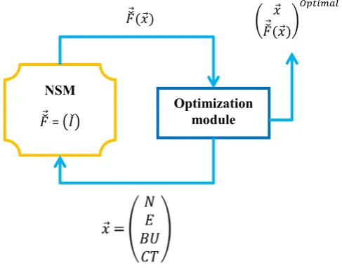
Furthermore, a very detailed analysis of the cask loading performances could be obtained by converting the linear inequalities system in a numerical surrogate model (NSM). For this purpose, based on an adapted design space exploration software, an optimization workflow (Fig. 3) is defined in order to optimize the relevant cask loading parameters choosen (⃗).
In this way, with a paralell coordinates plot (Fig. 4), the bounding loading plans regarding the level of heterogeneousness authorized are easily defined.
Figure 3: Optimization workflow using a NSM NSM
⃗ = Optimization module
⃗(⃗) ⃗
⃗(⃗)
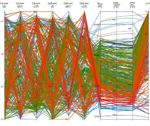
In order to illustrate the strength of this numerical optimization workflow, in Figures 4 to 7 are plotted all the loading plans allowing to optimize the loading of a dual purpose cask considering maximum radiation level (Imax) and maximum cask component temperature (Tmax). In this example, the cask basket, which presents more than 20 lodgements, is loaded in one or two different rows.
In Figure 4 are plotted all the possible loading plans if the cask basket is fully loaded with fuel assemblies (FA) presenting the same depletion characteristics (enrichiment (E), burnup (BU) and cooling time (CT)).
Figure 4: Paralell coordinates plot – Loading plans distribution – 1 loading row
For this cask loading strategy, it is interessant to see, that, whatever the FA depletion characteristics, the maximum FA and basket temperatures are always lower than respectively 300°C and 270°C, within a fulfilled inequality system. The maximum achievable total thermal power loaded (Qtotal) is 30,3 kW.
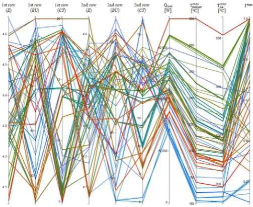
In Figure 5, using numerical filters, the loading plan possibilities are reduced in order to respect design constrains. For this cask loading strategy, a minimum cooling time of 14 years is required and the radiation levels are always higher than 80% of the thresholds.
In the same way, in Figure 6 are plotted all the loading plans if the same cask basket is devided in two rows and if the spent fuel assemblies loaded in the same row have the same depletion characteristics (enrichiment (E), burnup (BU) and cooling time (CT)).
In comparison with the previous strategy, those allows to increase the maximum achievable total thermal power loaded within a fulfilled inequality system.
Figure 5: Paralell coordinates plot – Numerical filter application – 1 loading row
In Figure 7, using numerical filters, the loading plan possibilities are reduced in order to respect design constrains. It is interessant to see that, for this cask loading strategy, large ranges for FA depletion characteristics (enrichiment (E), burnup (BU) and cooling time (CT)) are available. The maximum achievable total thermal power loaded (Qtotal) is 35 kW within a fulfilled inequality system.
Figure 6: Paralell coordinates plot – Loading plans distribution – 2 loading rows
Figure 7: Paralell coordinates plot – Numerical filter application – 2 loading rows
Furthermore, the time at which cask can only be used with a reduced loading capacity, because of remaining spent fuels with high burnups and low cooling times, is deferred and the cask availability and performances are strengthened (Ref. 5).
This directly contributes to a decrease in the total number of required cask loadings and shipments and a significantly decrease of all radiation exposures according to ALARA objectives.
5 Conclusions
In order to avoid unnecessary restrictions of the authorized content characteristics while still meeting the new requirements, AREVA TN has adapted its licensing process and developed a more elaborated shielding analysis method.
The linear inequalities system, resulting from the new shielding analysis method developed by AREVA TN, presents a high implementation flexibility and allows taking advantage of the explicit characteristics of the fuel assembly inventory. The relevant technical advantages of this approach are the following:
- It avoids the necessity of defining in the license a maximal burnup and a minimum cooling time authorized in order to respect the radiation level thresholds.
- It avoids the necessity of defining a matrix of bounding loading plans in order to allow heterogeneous loading plans.
- It does not require any dose rate calculation for each loading.
- It provides a simple and efficient tool in the form of linear inequalities to verify that the radiation level thresholds are met.
This method has been validated by the German authorities (BfS, TÜV) for the design approval of the dual purpose TN®24 E package. This method has been also implemented for the design approval of the transport casks TN®G3 and TN®17 MAX, and for the license renewals of the TN®24 BH, TN®24 SH, TN®24 GB and TN®9-4 package.
Furthermore the determined linear inequalities system associated with the assessment of the thermal loading constrains allows the use of highly heterogeneous loading plans with the largest practicable burnup and the shortest cooling time.
The use of this validated method is decisive in giving the cask user the maximum flexibility for an appropriate cask loading strategy definition with an optimized management of cask loading plan in the long term.
References
1. International Atomic Energy Agency, IAEA Safety Standards for protecting people and the environment,
Regulations for the Safe Transport of Radioactive Material,
Specific Safety Requirements, SSR-6 (2012 Edition)
2. International Atomic Energy Agency, IAEA Safety Standards for protecting people and the environment,
Regulations for the Safe Transport of Radioactive Material,
Safety Requirements, TSR-1 (2009 Edition)
3. S. KITSOS, Proc. of the 15th Int. Symposium on the Packaging and Transportation of Radioactive Materials, TN International Accurate Shielding Analysis for Casks, PATRAM 2007, Miami, Florida, USA, (October 21-26, 2007)
4. C. NICOLETTI et al., Proc. of the 5th french-speaking scientific days, Optimisation des Etudes en Radioprotection pour le Dimensionnement des Emballages de Transport et d’Entreposage de Matières Radioactives, Journées SFRP, Paris, France, (March 25-26, 2014)