Meson spectroscopy at COMPASS
Boris Grube1,
for the COMPASS Collaboration
1Institute for Hadronic Structure and Fundamental Symmetries, Physik-Department, Technische Universität
München
Abstract.The goal of the COMPASS experiment at CERN is to study the structure and dynamics of hadrons. The two-stage spectrometer used by the experiment has large acceptance and covers a wide kinematic range for charged as well as neutral particles and can therefore measure a wide range of reactions. The spectroscopy of light mesons is performed with negative (mostlyπ−) and positive (p,π+) hadron beams with a momentum of 190 GeV/c. The light-meson spectrum is measured in different final states produced in diffractive dissociation reactions with squared four-momentum transfertto the target between 0.1 and 1.0 (GeV/c)2. The flagship channel is theπ−π−π+final state, for which
COMPASS has recorded the currently world’s largest data sample. These data not only allow to measure the properties of known resonances with high precision, but also to observe new states. Among these is a new axial-vector signal, thea1(1420), with unusual
properties. Novel analysis techniques have been developed to extract also the amplitude of theπ−π+subsystem as a function of 3πmass from the data. The findings are confirmed by the analysis of theπ−π0π0final state.
1 Introduction
The COMPASS experiment [1] has recorded large data sets of the diffractive dissociation reaction
π−+p→(3π)−+p
recoilusing a 190 GeV/cpion beam on a liquid-hydrogen target. In this process, the
beam hadron is excited to some intermediate three-pion stateX−viat-channel Reggeon exchange with the target. At 190 GeV/cbeam momentum, Pomeron exchange is dominant. Diffractive reactions are known to exhibit a rich spectrum of intermediate statesX−and are a good place to search for states beyond the naive constituent-quark model. In the past, several candidates for so-called spin-exotic mesons, which haveJPCquantum numbers that are forbidden in the non-relativistic quark model, have been reported in pion-induced diffraction [2, 3].
The scattering process is characterized by two kinematic variables: the squared total center-of-mass energys, which is fixed by the beam energy, and the squared four-momentum transfer to the target t=(pbeam−pX)2<0. It is customary to use the reduced four-momentum transfer squaredt≡ |t|−|t|min instead oft, where|t|minis the minimum value of|t|for a given invariant mass ofX−. The analysis is performed in the range 0.1<t<1.0 (GeV/c)2.
In addition to the three final-state pions from theX−decays, also the recoiling proton is measured. This helps to suppress backgrounds and ensures an exclusive measurement by applying energy and
]
2 c GeV/
[
π 3 m
0.5 1 1.5 2 2.5
)
2c
Events / (5 MeV/
0 0.1 0.2 0.3 0.4
6 10 ×
(1260) 1 a
(1320) 2 a
(1670) 2 π
]
2 c GeV/
[
+
π
−
π
m
0.5 1 1.5 2
)
2c
Entries / (5 MeV/
0 0.5 1
6 10 ×
(770) ρ
(980) 0 f
(1270) 2 f
(1690) 3 ρ
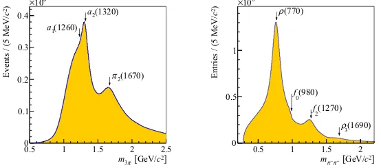
Figure 1.Left:π−π−π+invariant mass spectrum in the analyzed range; Right: invariant mass distribution of the
π−π+subsystem (two entries per event). Figures from Ref. [4].
momentum conservation in the event selection. After all selection cuts, the 3πdata samples consist of 46×106π−π−π+and 3.5×10⁶π−π0π0exclusive events in the analyzed kinematic region of three-pion mass, 0.5<m3π<2.5 GeV/c2. Figure 1 shows theπ−π−π+invariant mass spectrum together with that of theπ−π+subsystem. The known pattern of resonancesa1(1260),a2(1320), andπ2(1670) is seen in the 3πsystem along withρ(770), f0(980), f2(1270), andρ3(1690) in theπ−π+subsystem.
2 Partial-wave decomposition
In order to disentangle the different contributing intermediate statesX−, a partial-wave analysis (PWA) is performed. The PWA of the (3π)−final states is based on the isobar model, which assumes that the X−decays first into an intermediate resonance, which is called the isobar, and a “bachelor” pion (π− for theπ−π−π+final state;π−orπ0forπ−π0π0). In a second step, the isobar decays into two pions. In accordance with theπ−π+invariant mass spectrum shown in Fig. 1 right and with analyses by previous experiments, we include [ππ]S,ρ(770),f0(980), f2(1270), f0(1500), andρ3(1690) as isobars into the fit model. Here, [ππ]S represents the broad component of theππS-wave. Based on the six isobars, we have constructed a set of partial waves that consists of 88 waves in total, including one non-interfering isotropic wave representing three uncorrelated pions. This constitues the largest wave set ever used in an analysis of the 3πfinal state. The partial-wave decomposition is performed in narrow bins of the 3π invariant mass. Since the data show a complicated correlation of them3πandtspectra, eachm3πbin is further subdivided into non-equidistant bins in the four-momentum transfert. For theπ−π−π+channel 11 bins are used, for theπ−π0π0final state 8 bins. With this additional binning int, the dependence of the individual partial-wave amplitudes on the four-momentum transfer can be studied in detail. The details of the analysis model are described in Ref. [4].
− π × π−→π− π ! + + + "#$ + π − π − π % π π − π & ' &
*+ -#" ] 2 c GeV/ [ π 3 m
1 1.2 1.4 1.6 1.8 2 2.2
)
2c
Intensity / (20 MeV/
0 5 10 15 20 25 3 10 × P π (980) 0 f + 0 + + 1 2 ) c
< 1.0 (GeV/
t'
0.1 <
(1) Model curve
(1420) resonance 1
a (2)
(3) Non-resonant term
(3)
(2)
(1)
Figure 2.Left: Intensity of the 1++0+f0(980)πPwave summed over alltbins for theπ−π0π0(blue) and the π−π−π+(red, scaled to the intensity integral of theπ−π0π0channel) final states. Right: Result of a resonance-model
fit to theπ−π−π+data [5]. The data points correspond to the red points in the left figure.
] 2 c GeV/ [ π 3 m
1 1.2 1.4 1.6 1.8 2 2.2
Phase [deg] 200 − 100 − 0 100
200 f0(980)π P− 4++1+ρ(770)π G + 0 + + 1 2 ) c
< 0.113 (GeV/
t'
0.100 <
2 )
c
< 0.189 (GeV/
t'
0.164 <
2 )
c
< 0.724 (GeV/
t' 0.449 < ] 2 c GeV/ [ π 3 m
1 1.2 1.4 1.6 1.8 2 2.2
Phase [deg] 250 − 200 − 150 − 100 − 50 − 0 50 100 150
200 (980)π P− 1++0+ρ(770)π S 0 f + 0 + + 1 2 ) c
< 0.113 (GeV/
t'
0.100 <
2 )
c
< 0.189 (GeV/
t'
0.164 <
2 )
c
< 0.724 (GeV/
t'
0.449 <
Figure 3.Examples for relative phases of the 1++0+f0(980)πPwave with respect to the 4++1+ρ(770)πG(left)
and the 1++0+ρ(770)πSwave (right). The phases are shown for three differenttregions indicated by the color. Figures from Ref. [5].
2.1 Thea1(1420)
A surprising find in the COMPASS data is a pronounced narrow peak at about 1.4 GeV/c2in the 1++ 0+f0(980)πPwave (see Fig. 2). The peak is observed with similar shape in theπ−π−π+andπ−π0π0 channels and is robust against variations of the PWA model. In addition to the peak in the partial-wave intensity, rapid phase variations with respect to most waves are observed in the 1.4 GeV/c2region (see Fig. 3). The phase motion as well as the peak shape change only little witht.
In order to test the compatibility of the signal with a Breit-Wigner resonance, a resonance-model fit was performed using a novel method, where the intensities and relative phases of three waves [1++
0+f0(980)πP, 2++1+ρ(770)πD, and 4++1+ρ(770)πG] were fit simultaneously in all 11tbins [5].
Thea1(1420) signal is remarkable in many ways. It appears in a mass region that is well studied since decades. However, previous experiments were unable to see the peak, because it contributes only 0.25 % to the total intensity. Thea1(1420) is very close in mass to the 1++ground state, thea1(1260). But it has a much smaller width than thea1(1260). Thea1(1420) peak is seen only in the f0(980)π decay mode of the 1++waves and lies suspiciously close to theK K∗(892) threshold.
The nature of thea1(1420) is still unclear and several interpretations were proposed. It could be the isospin partner to thef1(1420). It was also described as a two-quark-tetraquark mixed state [6] and a tetraquark with mixed flavor symmetry [7]. Other models do not require an additional resonance: the authors of Refs. [8, 9] propose resonant re-scattering corrections in the Deck process as an explanation, whereas Ref. [10] suggests a branching point in the triangular rescattering diagram for
a1(1260)→K K∗(892)→K Kπ→ f0(980)π. The results of the latter calculation were confirmed by
the authors of Ref. [11]. Triangle singularities were also proposed as an explanation for the narrow
η(1405) [12, 13], for some of the near-thresholdXYZheavy-quark states (see e.g. Ref. [14]), and for the pentaquark candidatePc(4450) recently found by LHCb [15, 16]. More detailed studies are needed in order to distinguish between the different models for thea1(1420).
2.2 Extraction ofππS-wave isobar amplitudes from data
The PWA of the 3πsystem is based on the isobar model, where fixed amplitudes are used for the description of theπ−π+intermediate states. However, we cannot exclude that the fit results are biased by the employed isobar parametrizations. This is true in particular for the isoscalarJPC =0++isobars. In the PWA model, a broadππS-wave component is used, the parametrization of which is extracted from
ππS-wave elastic-scattering data [17]. In addition, the f0(980), described by a Flatté form [18], and
thef0(1500), parametrized by a relativistic Breit-Wigner amplitude, are included as isobars. In order to
study possible bias due to these parametrizations and to ensure that the observeda1(1420) signal is truly related to the narrowf0(980), a novel analysis method inspired by Ref. [19] was developed [4]. In this so-calledfreed-isobaranalysis, the three fixed parametrizations for the 0++isobar amplitudes are replaced by a set of piecewise constant complex-valued functions that fully cover the allowed two-pion mass range. This way the whole 0++isobar amplitude is extracted as a function of the 3πmass. In contrast to the conventional isobar approach, which uses the same isobar parametrization in different partial waves, the freed-isobar method permits different isobar amplitudes for different intermediate statesX−. A more detailed description of the analysis method can be found in Ref. [4].
The freed-isobar method leads to a reduced model bias and gives additional information about the
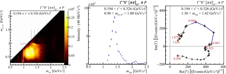
] 2 c GeV/ [ π 3 m
0.5 1 1.5 2 2.5
)
2c
Intensity / (40 MeV/
0 5 10
3 10
× 1++0+[ππ]0++π P
2 ) c < 0.326 (GeV/ t' 0.194 < P π + + 0 ] π π [ + 0 + + 1 2 c < 1.00 GeV/ + π − π m 0.96 < ] 1/2 ) ) 2 c Events/(GeV/ ( [ ) T Re(
0 200 400 600
] 1/2) ) 2c Events/(GeV/ ( [ ) T Im( 200 − 0 200 400 0.299 0.925 0.965 0.995 1.075 1.220 P π + + 0 ] π π [ + 0 + + 1 2 ) c < 0.326 (GeV/ t'
0.194 <
2 c < 1.42 GeV/
π 3 m 1.38 <
Figure 4.Left: Intensity of theππS-wave component of theJPCMε=1++0+partial wave resulting from the freed-isobar fit as a function ofmπ−π+ andm3π. Center: intensity as a function ofm3πsummed over themπ−π+
interval around the f0(980) indicated by the pair of horizontal dashed lines in the top figure. Right: Argand
diagram representing themπ−π+dependence of the partial-wave amplitude for the 3πmass bin at thea1(1420)
measured with respect to the 1++0+ρ(770)πSwave. Figures from Ref. [4].
(highlighted by the blue line) with a shifted origin. This demonstrates that the observeda1(1420) signal in the f0(980)πdecay mode is not an artifact of the 0++isobar parametrizations used in the conventional PWA method. More results of the freed-isobar PWA are discussed in Ref. [4].
2.3 TheJPC =1−+spin-exotic wave
The 88-wave model also contains waves with exoticJPCquantum numbers, that are forbidden in the non-relativistic quark model. The most interesting of these waves is the 1−+1+ρ(770)πPwave, which contributes less than 1 % to the total intensity. Previous analyses claimed a resonance, theπ1(1600), at about 1.6 GeV/c2in this channel [20, 21]. Figure 5 left shows the intensity sum over alltbins of this partial wave for the two final states (π−π−π+in red,π−π0π0in blue). The two distributions are scaled to have the same integral. Both decay channels are in fair agreement and exhibit a broad enhancement extending from about 1.0 to 1.8 GeV/c2 inm
3π. In the 1.0 to 1.2 GeV/c2 mass range, the intensity depends strongly on the details of the fit model. Peak-like structures in this region are probably due to cross talk induced by imperfections of the applied PWA model.
A remarkable change of the shape of the intensity spectrum of the 1−+1+ρ(770)πPwave withtis observed (see dark blue points in Fig. 5 center and right). At values oftbelow about 0.3 (GeV/c)2, we observe no indication of a resonance peak aroundm3π =1.6 GeV/c2, where we would expect the
π1(1600). However, for thetbins in the interval 0.449<t<1.000 (GeV/c)2, the observed intensities
exhibit a very different shape as compared to the low-tregion, with a peak structure emerging at about 1.6 GeV/c2and the intensity at lower masses disappearing rapidly with increasingt. This is in contrast
to clean resonance signals like thea2(1320) in the 2++1+ρ(770)πDwave, which, as expected, do not change their shape witht. The observedtbehavior of the 1−+intensity is therefore a strong indication that non-resonant contributions play a dominant role.
Figure 5.Intensity of the 1−+1+ρ(770)πPwave. Left: summed over alltbins for theπ−π−π+(red) and the
π−π0π0 (blue) final state. Center and right panels show the intensity for theπ−π−π+final state (dark blue) in different regions oft(center: lowt; right: hight). The partial-wave projections of Monte-Carlo data generated according to a model of the Deck effect are overlaid in green.
partial-wave projection of these Monte Carlo data is shown as green points in Fig. 5 center and right. In order to compare the intensities of real data and the Deck-model pseudo data, the Monte Carlo data are scaled to thet-summed intensity of the 1−+wave as observed in real data. At values oft below about 0.3 (GeV/c)2, the intensity distributions of real data and Deck Monte Carlo exhibit strong similarities suggesting that the observed intensity might be saturated by the Deck effect. Starting from t≈0.4 (GeV/c)2, the spectral shapes for Deck pseudo data and real data deviate from each other with the differences increasing towards larger values oft. This leaves room for a potential resonance signal. It should be noted, however, that the Deck pseudo data contain no resonant contributions. Therefore, potential interference effects between the resonant and non-resonant amplitudes cannot be assessed in this simple approach.
Acknowledgements
This work was supported by the BMBF, the Maier-Leibnitz-Laboratorium (MLL), the DFG Cluster of Excellence Exc153 “Origin and Structure of the Universe”, and the computing facilities of the Computational Center for Particle and Astrophysics (C2PAP).
References
[1] P. Abbon et al. (COMPASS Collaboration), Nucl. Instrum. Methods Phys. Res., Sect. A779, 69 (2015)
[2] C. Meyer et al., Phys. Rev. C82, 025208 (2010) [3] E. Klempt et al., Phys. Rept.454, 1 (2007)
[4] C. Adolph et al. (COMPASS Collaboration), arXiv:1509.00992,submitted toPhys. Rev. D (2015) [5] C. Adolph et al. (COMPASS Collaboration), Phys. Rev. Lett.115, 082001 (2015)
[6] Z.G. Wang, arXiv:1401.1134 (2014)
[7] H.X. Chen et al., Phys. Rev. D91, 094022 (2015)
[10] M. Mikhasenko et al., Phys. Rev. D91, 094015 (2015) [11] F. Aceti, L.R. Dai, E. Oset, arXiv:1606.06893 (2016)
[12] J.J. Wu, X.H. Liu, Q. Zhao, B.S. Zou, Phys. Rev. Lett.108, 081803 (2012) [13] X.G. Wu, J.J. Wu, Q. Zhao, B.S. Zou, Phys. Rev. D87, 014023 (2013) [14] A.P. Szczepaniak, Phys. Lett. B747, 410 (2015)
[15] R. Aaij et al. (LHCb Collaboration), Phys. Rev. Lett.115, 072001 (2015) [16] F.K. Guo, U.G. Meißner, W. Wang, Z. Yang, Phys. Rev. D92, 071502 (2015) [17] K.L. Au, D. Morgan, M.R. Pennington, Phys. Rev. D35, 1633 (1987) [18] M. Ablikim et al. (BES Collaboration), Phys. Lett. B607, 243 (2005) [19] E.M. Aitala et al. (E791 Collaboration), Phys. Rev. D73, 032004 (2006) [20] S.U. Chung et al. (E852 Collaboration), Phys. Rev. D60, 092001 (1999)
[21] M. Alekseev et al. (COMPASS Collaboration), Phys. Rev. Lett.104, 241803 (2010) [22] R.T. Deck, Phys. Rev. Lett.13, 169 (1964)