Image Processing Based Toll Gate Management System
Using ARM
Aashish.B & Yadaiah.K,
PG Scholar, Dept of ES, Professor,Head of ECE [email protected]
,
[email protected],St. Martins Engineering College, Jawaharlal Nehru Technological University, Hyderabad, Telangana, India.
Abstract:
This paper presents the look and development of vehicle plate recognition for machine-driven toll assortment. Since it's less complicated and quicker than the standard token primarily based price tag system, it's all the potential to exchange the present system. Moreover, it saves users valuable time by reducing the queue length before of the toll counter. it's accustomed pay the number mechanically and open & shut the toll gate mechanically.
An license plate is installed on each vehicle. A recognition device at the gate reads this data from the vehicle and compares it with the data in the computer database and allows the access accordingly by opening the gate. This data is used to print a daily or monthly bill for toll collection from the vehicles. we have a tendency to aim to scale back the time consumed to pay the toll gate quantity and conjointly to assist the RTO, department of local government to trace the vehicle, case if it had been taken or used for any ill-gotten activities. As we area unit planning to increase the safety options within the toll gate as a result of currently a day’s toll gate area unit the doorway to the most cities. If we have a tendency to increase the safety within the toll gate section mechanically the safety within the town are conjointly enhanced.
INTRODUCTION
Toll gates area unit sometimes thought-about associate degree inconvenience by travelers not just for the price of the toll, however conjointly for the delays at toll booths, toll roads and bridges. so as to confirm a gentle flow of traffic, each employees associate
degreed drivers need quick access to an economical communication system covering the precise necessities of toll gates. during this approach, hitches is resolved whereas maintaining a convenient toll gate system. Security systems also can be extra, which can any enhance the system.
The toll gate system mistreatment ANPR technology allows the electronic assortment of toll payments. This technology has been studied by researchers and applied in numerous highways, bridges, and tunnels requiring such a method. this technique is capable of deciding if the automobile is registered or not, so informing the authorities of toll payment violations, debits etc. the foremost obvious advantage of this technology is that the chance to eliminate congestion in tollbooths, particularly throughout merry seasons once traffic tends to be heavier than traditional. it's conjointly a technique by that to curb complaints from motorists concerning the inconveniences concerned in manually creating payments at the tollbooths. apart from this obvious advantage is that it might conjointly profit the toll operators.
statements (no ought to request for receipts). Different general blessings for the motorists embrace fuel savings and reduced mobile emissions by reducing or eliminating speed, waiting time, and acceleration.
Meanwhile, for the toll operators, the advantages through this technique area unit down toll assortment prices, higher audit management by centralized user accounts, distended capability while not building additional infrastructures. AUTOMATIC vehicle plate recognition (LPR) plays a vital role in various applications like unattended parking heaps security management of restricted areas traffic enforcement congestion evaluation and automatic toll assortment. thanks to completely different operating environments, LPR techniques vary from application to application. Paintable cameras produce dynamic scenes once they move, pan or zoom. A dynamic scene image could contain multiple vehicle plates or no license plate in the least.
Fig: Block Diagram
Moreover, once they do seem in a picture, license plates could have impulsive sizes, orientations and positions. And, if complicated backgrounds area unit concerned, detection
license plates will become quite an challenge. Typically, associate degree LPR method consists of 2 main stages (1) locating license plates and (2) distinctive license numbers. within the 1st stage, vehicle plate candidates area unit determined supported the options of license plates. options ordinarily utilized are derived from the vehicle plate format and therefore the alphanumerical characters constituting license numbers. The options concerning vehicle plate format embrace form, symmetry height-to dimension quantitative relation color texture of achromatic color spacial frequency and variance of intensity values Character options embrace line blob the sign transition of gradient magnitudes, the ratio of characters the distribution of intervals between characters and therefore the alignment of characters. In reality, alittle set of sturdy, reliable, and easy-to-detect object options would be adequate.
The vehicle plate candidates determined within the locating stage area unit examined within the identification number identification stage. There area unit 2 major tasks concerned within the identification stage, variety separation and variety recognition. variety separation has within the past been accomplished by such techniques as projection morphology relaxation labeling, connected parts and blob coloring. Since the projection methodology assumes the orientation of a vehicle plate is understood and therefore the morphology methodology needs knowing the sizes of characters. A hybrid of connected parts and blob coloring techniques is taken into account for character separation. Support Vector machine Andrei Markov processes and finite automata these strategies is loosely classified into repetitive and Non-iterative approaches. there's a exchange between these 2 teams of approaches; repetitive strategies reach higher accuracy, however at the price of enhanced time quality. For this, we have a
ARM 7
Pressure sensor
Gas Sensor
Switch
tendency to developed our own character recognition technique, that is predicated on the disciplines of each artificial neural networks and mechanics.
III. System Hardware
LPC2148 Processor:
LPC2148 Microcontroller Architecture. The ARM7TDMI-S is a general purpose 32-bit microprocessor, which offers high performance and very low power consumption. The ARM architecture is based on Reduced Instruction Set Computer (RISC) principles, and the instruction set and related decode mechanism are much simpler than those of micro programmed Complex Instruction Set Computers (CISC). This simplicity results in a high instruction throughput and impressive real-time interrupt response from a small and cost-effective processor core.
Pipeline techniques are employed so that all parts of the processing and memory systems can operate continuously. Typically, while one instruction is being executed, its successor is being decoded, and a third instruction is being fetched from memory. The ARM7TDMI-S processor also employs a unique architectural strategy known as Thumb, which makes it ideally suited to high-volume applications with memory restrictions, or applications where code density is an issue.
The key idea behind Thumb is that of a super-reduced instruction set. Essentially, the ARM7TDMI-S processor has two instruction sets:
•The standard 32-bit ARM set. •A 16-bit Thumb set.
The Thumb set’s 16-bit instruction length allows it to approach twice the density of standard
ARM code while retaining most of the ARM’s performance advantage over a traditional 16-bit processor using 16-bit registers. This is possible because Thumb code operates on the same 32-bit register set as ARM code. Thumb code is able to provide up to 65% of the code size of ARM, and 160% of the performance of an equivalent ARM processor connected to a 16-bit memory system
VIBRATION SENSOR
Vibration sensors detect the vibration of the ground soil in case of a debris flow. Prior to installing a vibration sensor, it is extremely important to determine what level of vibration is appropriate to activate the sensor in case of a debris flow. It is also important to keep in mind the risk of unintentional activation caused by earthquakes, as well as areas in which there is construction traffic and other vibration causes that may activate the sensor.
Fig: Vibration Sensor
• Machinery damage and costly production delays caused by unforeseen machinery failure can be prevented.
• When pending problems are discovered early, the plant engineer has the opportunity to schedule maintenance and reduce downtime in a cost effective manner.
• Vibration analysis is used as a tool to determine machine condition and the specific cause and location of machinery problems.
• This expedites repairs and minimizes costs
Ideal sensor for use to detect the presence of a dangerous LPG leak in your car or in a service station, storage tank environment. This unit can be easily incorporated into an alarm unit, to sound an alarm or give a visual indication of the LPG concentration. The sensor has excellent sensitivity combined with a quick repsonse time. The sensor can also sense iso-butane, propane, LNG and cigarette smoke.
Applications
Gas leak detection system Fire/Safety detection system Gas leak alarm
Gas detector
Features
High Sensitivity
• Detection Range: 100 - 10,000 ppm iso-butane propane
• Fast Response Time: <10s • Heater Voltage: 5.0V
• Dimensions: 18mm Diameter, 17mm High excluding pins, Pins - 6mm High
RS232 Communication RS232:
Information being transferred between data processing equipment and peripherals is in the form of digital data which is transmitted in either a serial or parallel mode. Parallel communications are used mainly for connections between test instruments or computers and printers, while serial is often used between
computers and other peripherals. Serial transmission involves the sending of data one bit at a time, over a single communications line. In contrast, parallel communications require at least as many lines as there are bits in a word being transmitted (for an8-bit word, minimum of 8 lines are needed).Serial transmission is beneficial for long distance communications, whereas parallel is designed for short distances or when very high transmission rates are required.
2.8.1 Standards: One of the advantages of a serial system is that it lends itself to transmission over telephone lines. The serial digital data can be converted by modem, placed onto a standard voice-grade telephone line, and converted back to serial digital data at the receiving end of the line by another modem. Officially, RS-232 is defined as the ” Interface between data terminal equipment and data communications equipment using serial binary data exchange.” This definition defines data terminal equipment (DTE) as the computer, while data communications equipment (DCE) is the modem. A modem cable has pin-to-pin connections, and is designed to connect a DTE device to a DCE device.
Fig: Pin Configuration of RS232
Null modem cables are designed for this situation; rather than having the pin- to-pin connections of modem cables, null modem cables have different internal wiring to allow DTE devices to communicate with one another.
2.8.3 Cabling Options: RS-232 cables are commonly available with 4, 9 or 25-pin wiring. The 25-pin cable connects every pin; the 9-pin cables do not include many of the uncommonly used connections; 4-pin cables provide the bare minimum connections, and have jumpers to provide “handshaking” for those devices that require it. These jumpers connect pins 4, 5 and 8, and also pins 6 and 20.
The advent of the IBM PC AT has created a new wrinkle in RS-232communications. Rather than having the standard 25-pinconnector, this computer and many new expansion boards for PC’s feature a 9-pin serial port. To connect this port to a standard 25-pin port, a 9-to-25-pin adaptor cable can be utilized, or the user can create his own cable specifically for that purpose.
2.8.4 Selecting a Cable: The major consideration in choosing an RS-232 cable is what devices are to be connected? First, are you connecting two DTE devices (null modem cable) or a DTE device to a DCE device (modem cable)? Second, what connectors are required on each end, male or female, 25-pin or 9-pin (AT style)? Usually, it is recommended that the user obtain the two devices to be connected, and then determine which cable is required.
2.8.5 RS232 Specifications:
Transmitted Signal Voltage
Levels:
Binary 0: +5 to +15 Vdc (called a “space” or “on”)
Binary 1: -5 to -15 Vdc (called a “mark” or “off”)
Received Signal Voltage
Levels:
Binary 0: +3 to +13 Vdc Binary 1: -3 to -13 Vdc
Data Format:
Start bit: Binary 0 Data: 5, 6, 7 or 8 bits
Parity: Odd, even, mark or space (not used with 8-bit data)
Stop bit: Binary 1, one or two bits.
• The USART input/output uses 0V for logic 0 and 5V for logic 1.
• The RS-232 standard (and the COM port) use +12V for logic 0 and –12V for logic 1.
• To convert between these voltages levels we need an additional integrated circuit (such as Maxim’s MAX232).
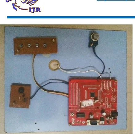
Figure 1 Hardware Peripherals
CONCLUSION:
Our system may be a user friendly toll fee methodology which might save time and scale back traffic jam at toll gates and supply answer for users to achieve their destination while not wastage of your time. It offers the toll authorities the flexibleness to line variable evaluation for toll services and so a good policy of assembling is followed. this manner there's no loss incurred by an individual carrying a vacant vehicle. With the hike of fuel costs in mind, consumption of fuel is additionally thought-about here because the speed, acceleration and inactivity is totally eliminated. Here there's no money dealings for the toll lanes, thus money handling is reduced. so difficulties with money handling area unit eliminated and this manner aid in increased audit management by centripetal user accounts. info like vehicle count over the time of the day, date, time etc is obtained thanks to the readying of this technology. This helps in creating choices concerning the evaluation ways for the toll suppliers. It conjointly helps planner to estimate the time period that aid in planning choices.
FUTURE ENCHANCEMENT
In future the speed of the process can be increased further. Similarly we can add an additional feature such as adding a metal detector in order to detect the arms that are carried.
REFERENCES
[1]
Kin Seong Leong, MunLeng Ng,
Member
,
IEEE
, Alfio R. Grasso, Peter H.
Cole, "Synchronization of RFID Readers for
Dense
RFID
Reader
Environments",
International Symposium on Applications
and the Internet Workshops (SAINTW’06),
2005
[2]
Manish
Buhptani,
ShahramMoradpour, "RFID Field Guide -
Developing Radio Frequency Identification
Systems", Prentice Hall, 2005, pp 7-9,
16-225, 160, 231
[3]
Raj Bridgelall, Senior Member,
IEEE, " Introducing a Micro-wireless
Architecture for Business Activity Sensing
", IEEE International Conference RFID,
April 16-17,2008
[4]
Sewon Oh, Joosang Park, Yongioon
Lee, "RFID-based Middleware System for
Automatic
Identification",
IEEE
International
Conference
on
Service
Operations and Logistics, and Information,
2005
[5]
Shi-Cho Cha Kuan-Ju Huang
Hsiang-Meng Chang, " An Efficient and
Flexible Way to Protect Privacy in RFID
Environment with Licenses ", IEEE
International Conference RFID, April
16-17,2008
[6]
UrachadaKetprom,
Author Profile:
B.AASHISH
received
Mtechin
ECE
Embedded
Systems
from
St.Martins
Engineering
College,
Dhulapally,
Seunderabad in 2017. He was graduated in
Electronics
and
Communication
Engineering from Institute of Aeronautical
Engineering collage ,Telangana, India in
2015.
Author Profile: