1 | P a g e
COMPARATIVE STUDY OF DC-DC
CONVERTERS FOR RECTIFIER POWER FACTOR
CONTROL
Neha R. Naik
1, Dr. H. G. Virani
21(Electronics & Telecommunication Engineering, Goa College of Engineering, India)
2(Electronics & Telecommunication Engineering, Goa College of Engineering, India)
ABSTRACT
Majority of the applications involving electronic circuitry require a regulated DC supply. Since AC supplies are
more commonly available, a suitable AC-DC converter becomes mandatory for such applications. . The input
stage of AC-DC converter comprises of a full-bridge rectifier followed by a large filter capacitor. The input
current of such a rectifier circuit comprises of large discontinuous peak current pulses that result in high input
current harmonic distortion. Thus the power factor is poor.
An active approach is the most effective way to correct power factor of electronic supplies. Here, different
Active PFC DC-DC converters (Buck, Boost, Buck-Boost, Cuk and Sepic)are placed between the bridge rectifier
and the load. The converter tries to maintain a constant DC output bus voltage and draws a current that is in
phase with and at the same frequency as the line voltage.
In this paper,different types of dc-dc converter topologies in continuous conduction mode (CCM) are studied
and a comparative analysis based on simulation results of various DC-DC converters (Buck, Boost, Buck-Boost, Cuk and Sepic)is presented. The PI controller is used to reshape the input current. Simulation studies have been carried out usingMATLAB/SIMULINK.
Keywords –
Buck, Boost, Buck-Boost, CCM,Power Factor.I. INTRODUCTION
The input stage of AC-DC converter comprises of a full-bridge rectifier followed by a large filter capacitor. The
input current of such a rectifier circuit comprises of large discontinuous peak current pulses that result in high
input current harmonic distortion. The high distortion of the input current occurs due to the fact that the diode
rectifiers conduct only for a short period. This period corresponds to the time when the mains instantaneous
voltage is greater than the capacitor voltage. Since the instantaneous mains voltage is greater than the capacitor
voltage only for very short periods of time, when the capacitor is fully charged, large current pulses are drawn
2 | P a g e
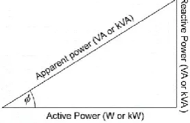
Power factor is defined as the cosine of the angle between voltage and current in an AC circuit. Total Electrical
Power = Voltage across the element * current through the element = V * I. This is called apparent power,
denoted by ‘S’and its unit is VA (Volt Amp).A fraction of this total electrical power which
does our useful work is called as active power or true power, denoted by ‘P’. Its unit is watt.P = Active power =
S.cosφ The other fraction of power is called reactive power. Reactive is required for the active work to be done, denoted by ‘Q’. Q = Reactive power = S.sinφ and its unit is VAR (Volt Amp Reactive).
To help understand this better all these power are represented in the form of triangle.
Fig. 1.1 Power Factor Triangle
Mathematically, S2 = P2 + Q2 and electrical power factor is pf=cosφ=P/S.
Power factor (pf) gives the measure of quality of a circuit. If the pf is unity, the entire power drawn from the
source is given to the load. However if the pfis low, the input source should be rated for a much higher power
than required by the load. This would result in higher line losses resulting in lower efficiency.
II. UNITY POWER FACTOR CONVERTER
The rectifier-capacitor filter circuit is the most popular for obtaining a DC voltage from the AC mains.
However, the input current is of pulsed nature and as a result the power factor is very poor. To improve the
power factor, DC-DC converters can be used as shown in Fig. 2.1(a). The power semiconductor switch of the
converters is controlled in such a manner that the input current is in phase with the rectified source voltage to
achieve unity power factor operation. The rectified source voltage that appears at the input to the converter is
shown in Fig. 2.1(b). The requirement for the input current of the converter is also shown. As shown in Fig.
2.1(b), the input current of converter should be in phase with the input voltage to achieve unity power factor.
3 | P a g e
Fig. 2.1(b) Required input current for unity power factor
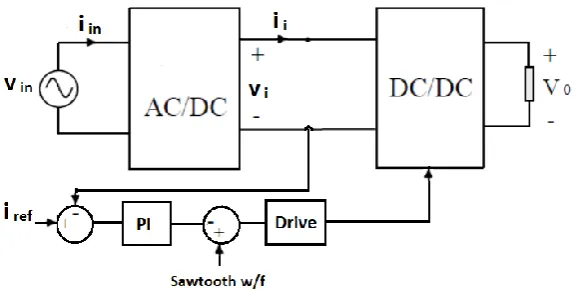
The control block diagram of the converter for unity power factor operation is shown in Fig. 2.2. The objective
of the controller is to control the input current of the converter. The input current ii of the converter is fed back
and compared with the reference iref that has a rectified sinusoidal wave shape such that it is in phase with the
converter input voltage vi. The error is passed to a PI controller.PI controller output is compared with saw tooth
signal to generate the PWM signal. The generated PWM is passed through the power switch drive circuit to turn
ON and OFF the converter switch. The PI controller make sure that the error at its input is zero, which implies
that ii tracks iref.
Fig. 2.2 Block diagram of the control scheme for power factor improvement
III. REFERENCE CURRENT GENERATION
The generation of a reference current,irefis important in this topology. iref should have a wave shape that follows
the wave shape of the rectified source voltage. The amplitude of iref is determined by the output power
requirement. Consider the input source voltage:
This vin is normalized and rectified to obtain:
Equation (2), defines the reference current wave shape. The amplitude is determined by the output power
requirement. If P0 is the output power, then:
4 | P a g e
From equation (4):
Equation (5) determines the amplitude of the reference current wave shape. From equations (3) and (5), the
reference current is given as:
IV.MODELLING OF DC-DC CONVERTERS
In order to design controller we need to have knowledge of DC-DC converter in mathematical form and this is
called Dynamic Modelling.
Dynamic Model: - State space representation
-Transfer function representation
When we do dynamic modelling we arrive at differential equations which is basically State space representation
and from state space representation we obtain transfer function representation.
State space representation:
State space representation is given in the form:
ẋ
For any system the mathematical model can be represented in the standard form of equations (7) and (8).Where
x is the nx1 state vectors which comprises the state variables for a system of order n. A is nxn system parameter
matrix which consist of the system constants. The B matrix is the nxm input matrix which weights the direct
input excitation for state variables. U is the mx1 input vector for m input excitations. Y is the px1 output vector
for p outputs from the system. C is a pxn output matrix and D is a pxm feed forward matrix.
Transfer function representation:
Taking the Laplace transform of the state equation and from the definition of the transfer function, the initial
conditions are zero. So we get:
(9)
Pre multiplying both sides of equation (9) by (sI-A)-1, one obtains:
5 | P a g e
The transfer function from the state space representation is given as:
DC-DC converter have only one nonlinear element i.e. switch. It has two states: ON and OFF.Due to this reason
classic control theory for designing controller cannot be applied directly some type of averaging model is
required to obtain the mathematical representation of different DC-DC converters and that method is called
circuit averaging.
Circuit Averaging:
The circuit averaging method is explained in the following steps:
Step 1:Large signal Model:
ẋ ;
ẋ
Step 2:Average Large-Signal Model:
ẋ ;
where ;
Step 3:Steady-State Model
Under steady state or equilibrium conditions: ; ;
For the steady-state conditions, equation (15) can be written as:
Step 4:Small signal Model:
The above equations can be expanded. Terms containing x̂.d̂ and d̂.û can be neglected and the steady state
terms . Thus, the resultant small signal model is given as:
6 | P a g e
Where
V. RESULT
DC-DC Converter topologies
Improved input current w/f Power Factor
Buck 0.654
Boost 0.925
Buck-Boost 0.535
VI. CONCLUSION
The power factor correction circuits have been simulated in MATLAB/SIMULINK.In this paper the
comparative study of the Buck, Boost and Buck-Boost topologies for active power factor correction in AC-DC
converters has been carried out. Mathematical modelling of all three converters has been done and controller
tuning is done by Nicholas Ziegler method. From the results, it is found that the Boost Converter topology for
7 | P a g e
REFERENCES
Papers:
[1]AbhinayaVenkatesan, Aiswarya Mohan, Gayathri. K, R.Seyezhai, comparative study of active power factor
correction in ac-dc.converters, International Journal of Electrical, Electronics and Data Communication, ISSN
(p): 2320-2084.
[2] A K M KamrulHasan, MdFaruque Hossain, Comparison of PFC Circuit Topologies, American Journal of
Engineering Research (AJER) e-ISSN: 2320-0847 p-ISSN : 2320-0936 Volume-5, Issue-7, pp-133-136.
[3]Daniel ALBU, Nicolae DRĂGHICIU, Gabriela TONŢ and Dan George TONŢ, Converters with Power
Factor Correction, ACTA ELECTROTEHNICA.
[4] Huai Wei and IssaBatarseh, Comparison of Basic Converter Topologies for Power Factor Correction,
Proceedings IEEE Southeastcon '98 'Engineering for a New Era'.
[5] SujataPowniker and Sachin Shelar, Development of Active Power Factor CorrectionController Using Boost
Converter, 2016 IEEE International WIE Conference on Electrical and Computer Engineering (WIECON-ECE)
[6] A. K. Mishra, M. K. Pathak and S. Das, Isolated converter topologies for power factor correction, 2011
International Conference on Energy, Automation and Signal.
[7] Yamamot ,KMatsui, and M.Matsuo,Acomparison of various DC-DC converters and their application to
power factor correction, Proceedings of the Power Conversion Conference-Osaka 2002 (Cat. No. 02TH8579)
Books:
[6] Power Electronics Essentials and Applications by L Ulmanand.
[7] Fundamentals of Power Electronics 2nd edition by Robert W. Erickson.