PI Controller and Fuzzy Logic Controller
based Loss Minimization Techniques for
Induction Motor Drives
Rahul Joge
1, A. S. Sindekar
2Research Scholar [EPS], Dept. of EE, Govt. College of Engineering, Amravati, Maharashtra, India1 Associate Professor and Head, Dept. of EE, Govt. College of Engineering, Amravati, Maharashtra, India2
ABSTRACT: This paper presents loss minimization techniques for a variable speed, three-phase, squirrel-cage, indirect vector controlled induction motor drive that minimizes total losses and optimizes efficiency through optimal
control using proportional plus integral (PI) and fuzzy logic controller. Loss minimization is obtained by proper designing of appropriate controller. Three phase stator current of an induction motor with d-q co-ordinates is referred to
the hysteresis band current controller for pulse width modulation. This transformation results in reduction of output voltage obtained from the three phase voltage source inverter and applied to the stator input terminals of induction motor drive, thus the decomposition into d-q components in the steady-state motor model can be utilized in deriving the reduced motor losses. The drive system is simulated using Matlab/Simulink models and simulation results based on total losses and efficiency are compared with changing load torque.
KEYWORDS: Fuzzy logic, PI controller, loss minimization, efficiency optimization, induction motor drive.
I. INTRODUCTION
The importance of the loss minimization for the induction motor drives may be realized from different perspectives because as far as the energy consumption is concerned the electric motors consume more than 50% of the electrical energy produced. Of this, the major share goes to induction motors, the main workhorse of industry. Also, they are most widely used in electrical drives because of their robustness, ruggedness, reliability and low cost. Despite of many advantages of induction motor there are some disadvantages also. Like it is not true constant speed motor, slip varies from less than 1% to more than 5%. Also it is not capable of providing high efficiency and low losses. But as it is so useful for industries we have to find some solution to solve these limitations and the solution is loss minimization controller that can take necessary action to reduce motor losses [1]-[2]. Not only reduce losses, but it can control various parameters of the induction machine such as flux, torque, voltage, stator current [4]. Out of the several procedures for loss minimization of an induction motor drive, voltage reduction when the motor is operating with light load is found to be the effective method used for obtaining reduced power losses [6]. In general, electrical motor drive contains losses like converter loss, motor loss and transmission loss. Thus in an effort to minimize the loss and improve efficiency of induction motor drive with different techniques, design and construction of some loss minimizing ideas are needed. This work presents a loss minimization model based techniques of induction motor drives. The efforts on loss minimization can be done through improved design of motor and converter by introducing better control techniques with the best result.
II
.
LOSSES IN INDUCTION MOTOR DRIVEThe process of energy conversion within motor drive leads to the power losses in the motor windings and magnetic circuit as well as conduction and commutation losses in the inverter.
Motor losses
on the form of stator and rotor slots and are frequency and load dependent. The total secondary losses (stray flux, skin effect and shaft stray losses) usually don‟t exceed 5% of the overall losses. Considering that the stray losses are of importance at overload conditions, while the efficiency optimizer is effective at light load, the stray losses are not considered as a separate loss component in the loss function.
III. LOSS MINIMIZATION
Loss minimization is inversely proportional to the efficiency maximization. The efficiency of electrical machines depends on the type, size and quotient of partial load over rated load. Improvement of the efficiency can be obtained with the following methods:
1. Reduction of size (replacement of the motor), when the motor permanently operates in an area of partial load. 2. Voltage reduction, when the motor is operating with light load.
3. Improvement of power factor of lightly loaded induction motor by reducing the stator voltage.
4. V/f ratio is kept constant which in turns maintains the magnetizing flux constant that eliminates harmonics problem and maximum torque also does not change.
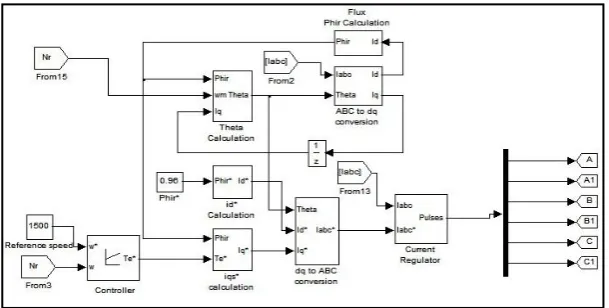
IV. INDIRECT VECTOR CONTROL SYSTEM
Indirect vector control principle was introduced by Blaschke in 1972. It states that the flux and torque can be controlled independently. It consists of dynamic d-q model which consists of voltage source inverter, flux calculation, theta calculation, current and voltage sensing elements. Fig. 1 shows a d-q model for indirect vector control system. Usually, a vector control technique provides the application of induction motor drives for improved and high performance. Indirect vector control system is somewhat similar as that of direct vector control except that the rotor angle θe is generated in an indirect manner using the measured speed ωr and slip speed ωsl. Following dynamic equations are
necessary to be take into consideration for the implementation of indirect vector control strategy.
The induction motor drive is fed by a 3 phase 6 step voltage source PWM inverter. In case of PI controller, the motor speed ωr and steady state error is produced is given to the speed controller. The output of PI controller generates a
reference command in the form of electromagnetic torque Te*. While considering the case of Fuzzy logic controller, the steady state error is introduced by comparing the slip and efficiency as the input to the controller. It generates the reference command in the same way as that of PI controller in the form of Te*.
The quadrature axis stator current reference is calculated by,
r e m r qs
T
L
L
P
i
ˆ
2
3
2
* *
(1)where
ˆ
r
r est.is the estimated value of rotor flux given by,s
i
L
r ds m r.
1
.
ˆ
(2) where, r r rR
L
is the rotor time constant.The direct axis stator current reference
i
ds*obtained from rotor flux input
r *,
m r ds
L
i
* *
(3)The rotor flux position
erequired for co-ordinates transformation is obtained from the rotor speed
rand slip speedsl
is calculated assl r sl
r e
e
dt
dt
The slip speed
slis calculated from the stator reference currenti
qs*and the motor parameters, given byqs r r
r m
sl
i
L
R
L
.
.
(5)The electromagnetic torque is,
qs r r m
e
i
L
L
P
T
.
2
2
3
(6)The iqs *
and ids *
current reference are converted into phase current references ia *
, ib *
and ic *
using inverse park transform (dq-abc) and fed to the hysteresis band current controller. The controller processes the measured and reference currents to produce inverter gating signals.
Fig. 1.d-q model for indirect vector controlled drive
V. THE APPLIED CONTROL STRATEGY
1. Proportional plus integral (PI) controller
The first technique adopted in this paper is by using PI controller. The PI controller is a device that produces an output signal which is proportional to the input signal. It improves the steady state tracking accuracy, disturbance signal rejection and relative stability. It also decreases the sensitivity of the system to the variation in parameters. The PI controller produces an output signal consisting of two value- one proportional to the input signal and other proportional to the integral of input signal. The concern of PI controller in the system is to reduce the speed loop error and increase the order and type of the system by one as shown in Fig. 2.
Fig. 2.PI controller
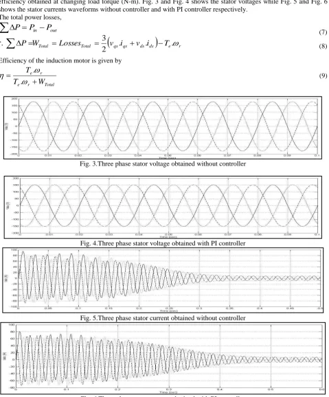
which in turns reduces the input power of the motor as compared to the power obtained without controller. This further reduces the total losses obtained on the rotor side improving the efficiency. Table 1 shows the values of total losses and efficiency obtained at changing load torque (N-m). Fig. 3 and Fig. 4 shows the stator voltages while Fig. 5 and Fig. 6 shows the stator currents waveforms without controller and with PI controller respectively.
The total power losses,
out in
P
P
P
(7)
qs qs ds ds
e rTotal
Total
Losses
v
i
v
i
T
W
P
.
.
.
2
3
(8)Efficiency of the induction motor is given by
Total r
e r e
W
T
T
.
.
(9)
Fig. 3.Three phase stator voltage obtained without controller
Fig. 4.Three phase stator voltage obtained with PI controller
Fig. 5.Three phase stator current obtained without controller
2. Fuzzy Logic Controller (FLC)
In other proposed control strategy, a fuzzy logic controller technique is used. It is made on the basis of nine rules fed into fuzzy set with two inputs and one output by proper modelling most of the parameters of induction motor (Stator and Rotor) and losses are taken under consideration. The simulation results are studied and taken for comparison in relation to their rotor speed of response, pulsation in torque and level of loss reduction and efficiency improvement. Fuzzy logic is a technique to inculcate human-like thinking into a control system. Hence, the main purpose of designing fuzzy controller is to embody the human intelligence or human like thinking in the controller to control the process parameters. To emulate human deductive thinking we design Fuzzy logic controller, that is, the process people use to infer conclusions from what they know. FLC has been primarily applied to the control of processes through fuzzy linguistic descriptions.
In a motor control system, the function of FLC is to convert linguistic control rules into control strategy based on heuristic information or expert knowledge. FLC approach is very useful for induction motor drives since no exact mathematical model of the induction motor or the closed-loop system is required. FLC has a fixed set of control logic rules, usually derived from the knowledge of experts. The membership function (MF) of the associated input and output linguistic variables is generally predefined on a common universe of discourse. For the successful design of FLC proper selection of input and output or tuning of the other controller parameters provides crucial jobs, which in several cases are done through trial and error to achieve the best possible control performance. For designing a fuzzy logic based controller, first thing we have to decide is what will be the inputs. As our main aim is to provide constant speed during load changes so the variable to be controlled will be speed.
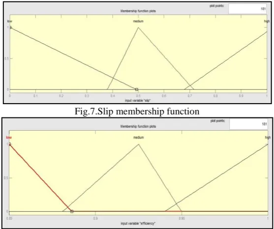
The slip and efficiency are given as input to the fuzzy controller. The fuzzy logic controller initially converts the slip and efficiency in displacement into fuzzy variables; then they are mapped into linguistic labels. Membership functions are defined within the normalized range (-1, 1), and associated with each label: Low, Med (medium) and High. Three MFs are chosen for slip and efficiency signals and three for output. All the MFs are symmetrical for positive and negative values of the variables. Thus, maximum 3х3 = 9 rules can be formed. The membership function for the inputs (error slip and efficiency) and output of fuzzy controller are shown in Fig. 7, 8 and 9 respectively.
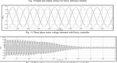
Fig. 11 and Fig. 12 shows the stator voltage (Vabc) and stator current (Iabc) waveforms obtained by applying Fuzzy logic
controller. The values on both the waveforms are of reduced magnitude which affects the performance improvement in deriving low losses and optimized efficiency at changing load torque.
Fig.7.Slip membership function
Fig.9.Output membership function
Fig. 10.Input and output surface for fuzzy inference module
Fig. 11.Three phase stator voltage obtained with Fuzzy controller
Fig. 12.Three phase stator current obtained with Fuzzy controller
VI
.
PULSE WIDTH MODULATIONHysteresis Band Current Controller
The main aim of PWM technique is to generate output voltage with maximum fundamental component and minimum harmonics. Hysteresis band current controller has fast response of current loop and good accuracy. It does not require any knowledge of system parameters. It is an instantaneous feedback current controller in which command current is continuously tracked by the output current within pre-assigned hysteresis band. The switching logic is formulated as follows:
If Iabc < Iabc*, upper switch is turned ON and lower switch is OFF.
If Iabc > Iabc*, upper switch is turned OFF and lower switch is ON.
The bandwidth of the hysteresis band current controller determines the allowable current shaping error. By reducing the bandwidth the user can increase the inverter operating frequenncy with improved harmonic wave quality. But it will increase switching losses. The hysteresis band current controller scheme is shown in Fig. 13.
Fig. 13.Hysteresis band current controller
VII. SIMULATION RESULTS
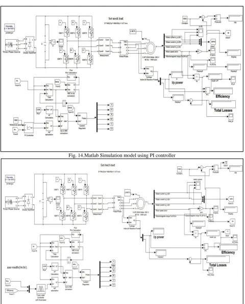
Fig. 14.Matlab Simulation model using PI controller
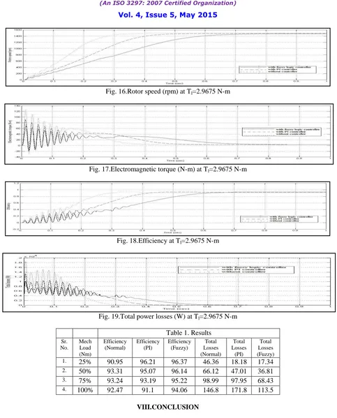
Fig. 16.Rotor speed (rpm) at Tl=2.9675 N-m
Fig. 17.Electromagnetic torque (N-m) at Tl=2.9675 N-m
Fig. 18.Efficiency at Tl=2.9675 N-m
Fig. 19.Total power losses (W) at Tl=2.9675 N-m
Table 1. Results
Sr. No.
Mech Load (Nm)
Efficiency (Normal)
Efficiency (PI)
Efficiency (Fuzzy)
Total Losses (Normal)
Total Losses
(PI)
Total Losses (Fuzzy) 1. 25% 90.95 96.21 96.37 46.36 18.18 17.34 2. 50% 93.31 95.07 96.14 66.12 47.01 36.81 3. 75% 93.24 93.19 95.22 98.99 97.95 68.43
4. 100% 92.47 91.1 94.06 146.8 171.8 113.5
VIII.CONCLUSION
increasing at changing load torque. Fuzzy logic controller technique is found to be more effective over PI controller technique for efficiency optimization and loss minimization.
REFERENCES
[1] M. Nasir Uddin and Sang Woo Nam, “New online Loss-Minimization-Based Control of an Induction Motor Drive” IEEE transactions on power electronics, Vol. 23, No. 2, pp.926-933, March 2008.
[2] M. Nasir Uddin and Sang Woo Nam, “Development of a Non linear and model based online loss minimization control of an IM drive” IEEE transactions on energy conversion, Vol.23, No.4, pp.1015-1024, December 2008.
[3] C. Chakraborty and Y. Hori, “Fast efficiency optimization techniques for the indirect vector-controlled induction motor drives,” IEEE Transactions on Industry Applications, Vol. 39, No. 4, pp.1070–1076, Jul./Aug. 2003.
[4] Zengcai Qu, Mikaela Ranta, Marko Hinkannen and Jorma Luomi “Loss minimizing flux level control of induction motor drives” IEEE transactions on industry applications, Vol. 48, No. 3, May/June 2012.
[5] Bijan Zahedi and Sadegh Vaez-Zadeh “Efficiency optimization control of single phase induction motor drives” IEEE transactions on power electronics, Vo l. 24, No. 4, pp.1062-1071, April 2009.
[6] D. Archana, Kotyada. Kalyani and B. Shankar Prasad “ Efficiency Optimization Control of Induction Motor Using Fuzzy Logic ” IJSCE, Vol. 2, Issue-3, pp.327-332, July 2012.
[7] Hussein Sarhan “ Efficiency optimization of vector-controlled induction motor drives” IJAET, Vol. 7, Issue 3, pp.666-674, July 2014.
[8] Mohamed Rachid Chekkouri, Jordi Català i López, Emiliano Aldabas Rubira and Luis Romeral Martínez “Fuzzy Adaptive Control of an Induction Motor Drive” ATKAAF, 44(3–4), pp.113–122, (2003).
[9] Hussein Sarhan, Rateb Issa, Mohammad Alia and Jamal M. Assbeihat „„Slip Compensation in Efficiency-Optimized Three-Phase Induction Motor Drive Systems ‟‟ Intelligent Control and Automation, Vol. 2, pp.95-99, May 2011.
APPENDIX
Specifications of Induction Motor
Nominal Power 3 HP Rotor Resistance 0.816 Ω Voltage (Line to line) 220 V Rotor Inductance 0.002 H Frequency 50 Hz Moment of Inertia 0.089 Kg-m2 Stator Resistance 0.435 Ω Number of Poles 4 Stator Inductance 0.002 H Synchronous speed 1500 rpm
NOMENCLATURE
iqs Stator current in synchronous frame on q-axis (A)
ids Stator current in synchronous frame on d-axis (A)
Rs Stator resistance (Ω)
Rr Rotor resistance (Ω)
Lr Rotor leakage inductance (H)
Lm Mutual inductance (H)
ωs Synchronous speed (rpm)
ωr Rotor speed (rpm)
ωsl Slip speed (rpm)
P Number of poles of IM Te Electromagnetic torque
(N-m)
Pin Input power (W),
Pout Output power (W)
Ψr
Rotor flux (Wb)r