Unique Auto Pest O Flash Control System Using Universal
Pid Controller Along With Induction Motor
1
DhammadipWasnik P.G.Student , Department of Electrical
Engineering,
TulsiramjiGaikwad-Patil College of Engineering & Technology,
Nagpur, India
2
Hari Kumar Naidu, HOD,
Department of Electrical Engineering,
TulsiramjiGaikwad-Patil College of Engineering & Technology,
Nagpur, India [email protected]
3
Pratik Ghutke, Guide ,
Department of Electrical Engineering,
TulsiramjiGaikwad-Patil College of Engineering & Technology,
Nagpur, India
ABSTRACTS:The intent of this project is the auto pest control and the speed control of induction motor using VFD and PID controller This paper describes the monitoring of pest insect population by using wireless sensor network in field. Monitoring pest insect population is very big issue in crop protection. At farm level it is continuously check by a human operator for adhesive traps, disseminated through the field, where insects remain stuck when attracted. This is a labor and time-taking activity, and it would be of great advantage for farmers to have an affordable system doing this task automatically. This paper illustrates a system based on a distributed imaging device operated through a wireless sensor network that is able to automatically acquire and transmit images of the trapping area to a remote host station. The station evaluates the insect density evolution at different farm sites and produces an alarm when insect density goes over threshold. The network architecture consists of a master node hosted in a PC and a set of client nodes,
Spreadin the fields that act as monitoring stations.
KEYWORDS:- Load (Motor), PID
(Proportional integral derivative controller), VFD (Variable Frequency Drive), speed reference control , relay unit, sensors. Pest control circuit.
INTRODUCTION: -Pest control is not a popular topic of interest and yet, it is part of everyone’s property maintenance list. For centuries pest removal has been a serious concern for people. Actually, it became a part of our lives since we first started growing crops as a way of survival. Through the centuries pest removal has evolved into several types of pestcontrolwhich have all proved to be effective in their own way. Nowadays, pests reach beyond crops and attack food, furniture, carpets and use people as a food source, as well.
Variable frequency drive is basically used where the variable speed is essential. It is a device in electrical system which performs the conversion of single phase or three phase supply of Fixfrequency into three phase supply with variable frequency. It is used for the application of variable speedrequirement .Due to smooth operation it has widely
Use in the application of speeds control of motor. It can becontrolled either manually or automatically. In over application it is
controlled automatically by using PID
Controllers.It helps the operator to vary the speed of motor automatically. The operation is carried out by using PID(Proportional integral derivative Controller). Reversing, switching and braking are additional function performed byVFD.
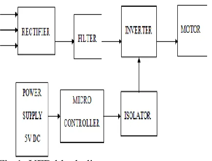
Fig 1: VFD block diagram
II. PID (Proportional integral derivative controller)
The PID controllers (proportional integral derivative controller) are widely used in industries for the speed control purpose. A PID controller calculates an “error” value as the difference between the measured process value and the desired set point. The PID controller
calculation involves three separate constants and is accordingly sometimes called three-term control i.e. the proportional, the integral and derivative value which is denoted by P, I and D
Fig 2: PID block diagram
A proportional controller may not give steady state error performance which is needed in the system. An integral controller may give steady state error performance but it slows a system down. So the addition of a derivative term helps to cure both of these problem. The final form of PID algorithm is
U(t) = MV(t) = KpU(t) +Ki ∫ ( ) +
Kd ( )
Proportional term:- Process variables for different Kp values (Ki and Kd held constant)
Fig.3.Process variables for different Kp
Process variables for different Kp values (Ki and Kdheld constant) are shown in Figure 4.5. The proportional term makes a change to the output that is proportional to the current error value. The proportional response can be adjusted by multiplying the error by a constant Kp, called the proportional gain.
A high proportional gain results in a large change in the output for a given change in the error. If the proportional gain is too high, the system can become unstable (see the section on loop tuning). In contrast, a small gain results in a small output response to a large input error, and a less responsive or less sensitive controller. If the proportional gain is too low, the control action may be too small when responding to system disturbances. Tuning
Theory and industrial practice indicate that the proportional term should contribute the bulk of the output change. A pure proportional
controller will not always settle at its target value, but may retain a steady-state error.
Specifically, drift in the absence of control, such as cooling of a furnace towards room
temperature, biases a pure proportional
controller. If the drift is downwards, as in cooling, then the bias will be below the set point, hence the term "droop. Droop is
proportional to the process gain and inversely proportional to proportional gain. Specifically the steady-state error is given by
e = G / Kp
Droop is an inherent defect of purely
proportional control. Droop may be mitigated by adding a compensating bias term (setting the set point above the true desired value), or corrected by adding an integral term.
Integral Term:-
Fig.4. Process variable for different Ki
Process variables for different Ki values (Kp and Kd held constant) are shown in figure above The contribution of the integral term is
proportional to both the magnitude of the error and the duration of the error. The integral in a PID controller is the sum of the instantaneous error over time and gives the
then multiplied by the integral gain (Ki) and added to the controller output.
The integral term is given by the Equation
Iout = Ki ∫ ( )
The integral term accelerates the movement of the process towards set point and eliminates the residual steady-state error that occurs with a pure proportional controller. However, since the integral term responds to accumulated errors from the past, it can cause the present value to overshoot the set point.
Derivative term:-
Fig. 5. Process variable for different Kd The derivative term is given by the Equation
Dout = Kd c(t)
The derivative term slows the rate of change of the controller output. Derivative control is used to reduce the magnitude of the overshoot produced by the integral component and improve the combined controller process
stability. However, the derivative term slows the transient response of the controller. Also, the differentiation of a signal, amplifies noise and
thus this term in the controller is highly sensitive to noise in the error term, and can Cause a process to become unstable if the noise and the derivative gain are sufficiently large. Hence an approximation to a differentiator with a limited bandwidth is more commonly used. Such a circuit is known as a phase-lead compensator.
Advantages of PID controller include the following: i. Very less oscillation.
ii. Low overshoot. iii. Faster and no offset.
iv. An integral term gives zero steady state error for step input.
v. An derivative term often produce faster response.
III. PROPOSED SYSTEM:-
Proposed system block diagram shown in Fig.3 and it consists of 230 V supply. This 230V supply step down to the voltage required for relay unit as shown in block diagram. Relay unit will give the signal to motor according to density of pest around the light source.
Fig 6: Block diagram of overall system
.The speed of the motor is controlled by varying the frequency through Pulse width modulation controller. The variable frequency is set by using VFD. The VFD is connected with motor. By changing the output frequency the motor speed can be varied.
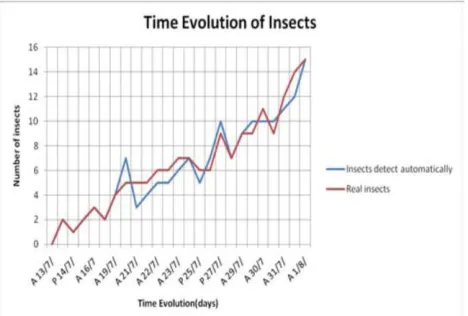
Fig. 7 Time evolution of the number of insects as automatically detected and counted
CONCLUSIONS:-
The results of this study demonstrated the feasibility of pest insect automatic monitoring on the field, by wireless sensor networking. Further research is still needed to improve the robustness of the measurements, to obtain more specific information (discriminating insect species or typology) and to demonstrate the cost and environmental benefit of such a system. In this project we just found the insect count and we are not controlling so further we can develop the system for controlling the pest insects.
REFERENCES:-
(1) AungZawLatt, Ni Win, “Variable speed drive of single phase induction motor using frequency control method,” IEEE Int. Conf. Education Technology and Computer, pp.30-34.
(2) BimalK.Bose, “Modern Power Electronics and AC Drives”, Pearson education.
[3] Gopal, M., “Modern Control System Theory”, 2nd ed., Wiley Eastern Ltd., 1993. (4) Krishnan, R. “Electric Motor Drives, Modeling, (Analysis and Control”, 1st ed., Singapore: Pearson Education, 2001. .
(5) AM Shelton, FR Badness “Concepts and Applications of Trap Cropping In Pest management” published by department Of Entomology, Cornell University, New York State Agricultural Experiment in IEEE2006.
(6)Yuee Liu, Jinglan Zhang “Towards
Continuous Surveillance of Fruit Flies Using
Sensor Networks and Machine Vision”
published by the department of networking and mobile computing Microsoft QutEresearch Centre in IEEE2009.
(7)GeorgiyPekhteryev, ZaferSahinoglu,