MIMO Antenna Mutual Coupling Reduction for WLAN Using Spiro
Meander Line UC-EBG
Niraj Kumar* and Usha K. Kommuri
Abstract—This paper presents designs of novel E-plane spiro meander line uniplanar compact electromagnetic bandgap (E-SMLUC-EBG) and H-plane spiro meander line uniplanar compact electromagnetic bandgap (H-SMLUC-EBG) structures. The proposed EBG has been applied in mutual coupling reduction of a dual-element multiple input multiple output (MIMO) antenna system for WLAN by placing an EBG structure between the radiating antennas. Compact size of EBG helps in reducing the edge to edge distance between antennas which is 0.14λ0in this case, and it increases the compactness of integrated circuit. It gives 19 dB and 11 dB simulated mutual coupling reduction inE-plane and H -plane respectively at 5.8 GHz. Measured isolation improvement of 20.3 dB forE-plane and 14.7 dB for
H-plane has been achieved. This coupling reduction is also confirmed by surface current and correlation coefficient plots. The four-element (2×2) MIMO antenna system with proposed EBG is also simulated.
1. INTRODUCTION
MIMO antennas are in demand for wireless communication applications due to their compact size and ease of integration. However, the mutual coupling between the radiating elements of a MIMO antenna is still a nightmare for researchers. Traditionally, the minimum distance between the elements of a MIMO antenna should be half of the operating wavelength (0.5λ0) for a desirable isolation and better performance [1]. However, in order to fulfill the increased demand of compactness in MIMO system, we tend to decrease the spacing between the radiating antenna elements which results in high mutual coupling between them. This increased coupling can distort the radiation properties of the MIMO antenna. Electromagnetic coupling between the radiating elements is mainly due to surface wave, space wave and near field coupling. Surface waves are weakly excited in thin substrate, but space wave dominantly increases the coupling. Near-field coupling is also very strong in closely spaced antennas on a dielectric substrate of low permittivity. However, the increased demand of compactness in MIMO system requires reduced space between the radiating elements as well as low mutual coupling between them.
Various effective techniques have been used to achieve mutual coupling reduction in MIMO antenna system. Metamaterials [1, 7], different shapes of resonator [2, 6, 8, 9] and EBG structure [3–5, 10] are the mostly used methods to reduce mutual coupling effectively. Some structures have used defective ground structure (DGS) [6], but it increases back radiation which is undesired. By using a mushroom type EBG [4] we can overcome this radiation pattern degradation, but the vias (plated through holes) result in electric loss and increased fabrication complexity. This complexity is removed by removing the vias and using a uniplanar compact EBG (UC-EBG) [3, 5, 10]. Most papers presented before have shown reduction either inE-plane orH-plane. Very few have shown reduction for both E- and H-planes [1].
In this paper, we present a Spiro Meander Line Uniplanar Compact Electromagnetic Bandgap (SMLUC-EBG) structure to reduce mutual coupling between closely spaced co-planar radiating
Received 16 October 2017, Accepted 21 November 2017, Scheduled 5 December 2017 * Corresponding author: Niraj Kumar ([email protected]).
microstrip antennas with edge to edge spacing of 0.14λ0. Two slightly different structures of SMLUC-EBG have been used for E and H-plane coupling reduction. E-SMLUC-EBG is for E-plane and H-SMLUC-EBG for H-plane mutual coupling reduction. Transmission line model has been used to find the working of unit cell of EBG structure which shows 20 dB (E-plane) and 13 dB (H-plane) reductions in transmission coefficient at WLAN frequency range. Application of these compact EBGs to MIMO antenna system provides 19 dB and 11 dB mutual coupling reduction in E-plane and H -plane, respectively, at 5.8 GHz (WLAN). Effect on the radiation properties of MIMO antenna due to the employment of EBG is analyzed and discussed.
2. DESIGN METHODOLOGY FOR E-PLANE MEANDER LINE
ELECTROMAGNETIC BANDGAP STRUCTURE (E-SMLUC-EBG) FOR WLAN
2.1. Design of Unit Structure of E-SMLUC-EBG
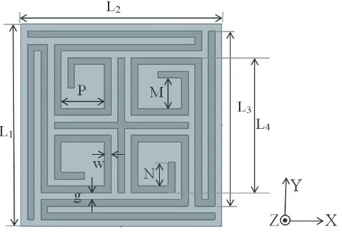
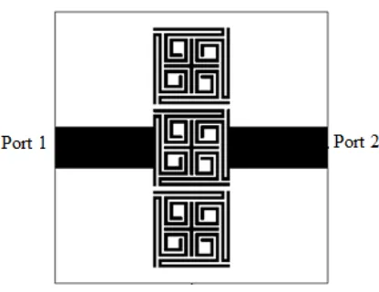
Unit cell of the Spiro Meander Line Uniplanar Compact Electromagnetic Bandgap structure forE-plane coupling reduction (E-SMLUC-EBG) is designed on a low cost FR4 substrate with dielectric constant 4.4 and height 1.6 mm using ANSYS High Frequency Structural Simulator (HFSS) as shown in Figure 1. The proposed unit structure is compact in size (6 mm×6 mm), and the area of 5.8 mm×5.8 mm is used for the closely spaced spiromeander line and cross structure at center with dimensions as shown in Table 1. Line width and gap between the lines is 0.2 mm. Lengths of the lines are optimized, and unit cells are analyzed using transmission line model to get desired low transmission at 5.8 GHz.
Figure 1. Unit structure of proposed E-SMLUC-EBG.
Table 1. Optimized values of parameters of unit cell of proposed E-SMLUC-EBG.
Parameters Optimized Values (mm)
L1 6
L2 6
L3 5.2
L4 4
M 0.9
N 0.7
P 1.3
w 0.2
The design progress of the E-SMLUC-EBG unit cell in six steps and corresponding graph for transmission coefficient S21 are shown in Figure 2 and Figure 3, respectively. It is clear from Figures 2 and 3 that increase in length of the meander line results in decrease in the resonating frequency. Thin lines of EBG work as inductor, and the reason for this frequency shift lies in dependency of the frequency on equivalent capacitor and inductor values. As the line length increases, equivalent inductance also increases which results in decrease in frequency. The final (stage 6) design is optimized to get 22 dB reduction in S21 at the resonant frequency at 5.8 GHz.
Figure 2. Design progress of the proposed EBG unit cell.
Frequency (GHz)
3 4 5 6 7 8 9
Tra
nsmission coe
fficie
nt
-35 -30 -25 -20 -15 -10 -5 0
1 2 3 4 5 6
Figure 3. Effect of design progress of the proposed EBG unit cell on transmission coefficient
S21.
2.2. Circuit Analysis of Unit Cell of Proposed EBG
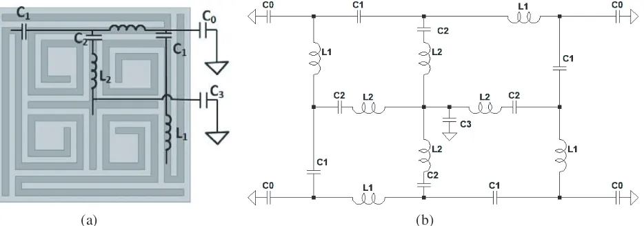
Equivalent circuit for the proposed EBG is shown in Figure 4. Inductance and capacitance developed on EBG are drawn in Figure 4(a) based on [11]. Parameter values are shown in Table 2 for the final stage. In this circuit, L1 is the inductance of one arm of spiro meander line, and L2 is the inductance of one arm of cross structure at center. C0 is capacitance formed between one arm of the spiro meander line and ground. C1 is capacitance between two adjacent arms of the spiro meander lines. C2 is capacitance between one arm of the spiro meander line and one arm of cross structure at center at the same side.
(a) (b)
Table 2. Parameter values for the equivalent circuit shown in Figure 4.
parameters L1 L2 C1 C2 C0 C3
value 12.9 nH 1.6 nH 0.05 pF 0.012 pF 0.91 pF 0.47 pF
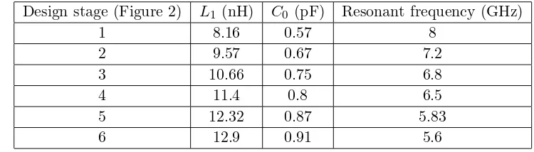
Table 3. Variation of L1 and C0 and corresponding resonant frequency for different cases shown in Figure 2.
Design stage (Figure 2) L1 (nH) C0 (pF) Resonant frequency (GHz)
1 8.16 0.57 8
2 9.57 0.67 7.2
3 10.66 0.75 6.8
4 11.4 0.8 6.5
5 12.32 0.87 5.83
6 12.9 0.91 5.6
C3 is capacitance between cross structure at center and ground. In the design stages of EBG unit cell of Figure 2, L2, C1, C2, C3 will remain constant. Circuit analysis for resonant frequency is done by LTSpice software. Table 3 shows the variation of L1 and C0 and corresponding resonant frequency for design stages of unit cell of EBG in Figure 2.
From Table 3 we can observe that increasing the line length causes increase in equivalent inductance and capacitance, and hence the resonant frequency of the EBG gets reduced according to resonant frequency formula (1) given below. The analyzed results are in good match with simulated ones.
f = 1
2π√Leq×Ceq (1)
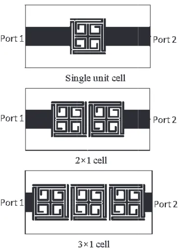
2.3. Analysis of Effect of Multiple Unit Cells on Transmission Coefficient S21
Transmission line analysis for one, two and three E-SMLUC-EBG unit cells together is shown in Figure 5, and effect of increasing the number of EBG unit cells on transmission coefficientS21is shown in Figure 6.
S21 for all the cases have been compared with that of 50 Ω transmission line which clearly shows that the transmission coefficient decreases as number of unit cells is increased from one to three. We get 22 dB, 34 dB and 40 dB of reductions using single, double and triple unit cells at frequencies 5.61 GHz, 5.72 GHz and 5.8 GHz, respectively.
3. IMPLEMENTATION OF E-SMLUC-EBG IN MUTUAL COUPLING REDUCTION OF E-COUPLED MIMO ANTENNA FOR WLAN
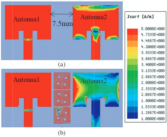
A single microstrip patch antenna has been designed on an FR4 substrate with dielectric constant 4.4 and height 1.6 mm using ANSYS High Frequency Structural Simulator (HFSS) for WLAN as shown in Figure 7 having dimension as depicted in Table 4. We have taken a basic MIMO antenna with two ports as shown in Figure 8(a). Electric field in MIMO antenna gets coupled though the radiating edges, hence three unit cells of the proposed E-SMLUC-EBG are applied between the radiating edges of antennas to reduce E-plane coupling as shown in Figure 8(b). To accommodate the proposed EBG structure between the MIMO antennas, the edge to edge distance is optimized as 7.5 mm, i.e., 0.14λ0.
Figure 5. Transmission line analysis of one two and three cells of E-SMLUC-EBG structure.
Transm
ission co
efficient (S2
1)
-4.0 4.5 -50
-40 -30 -20 -10 0
Frequ 5.0 5.5
uency (GHz)
6.0 6.5 7.0 7.5
single unit ce 2 x1 cell 3 x1 cell 50 0hm line
8.0
ell
Figure 6. Transmission coefficient S21 graph for single, two and three cells of E-SMLUC-EBG structure.
Figure 7. Microstrip patch antenna for WLAN.
(b) (a)
Figure 8. Surface current in MIMO antenna for WLAN, (a) without EBG and (b) with EBG showing reduced mutual coupling.
coefficient decreases significantly by 19 dB at 5.8 GHz with application of EBG between the gaps of radiating edge of antennas. Correlation coefficient is another performance metric parameter to show the mutual coupling in a MIMO antenna system. It shows level of coupling in the range of 0 to 1, and it can be calculated by using S-parameters. Correlation coefficient vs Frequency plot in Figure 10 shows reduced coupling of the MIMO antenna system with the proposed EBG structure.
Table 4. Optimized values of parameters of Microstrip patch antenna for WLAN.
Parameters Value (mm) Parameters Value (mm)
L 11.75 L3 10
W 15.74 wf 3
L1 20 m 3
L2 18 n 1.7
Frequency (GHz)
4.5 5.0 5.5 6.0 6.5 7.0
S11/ S21 (dB)
-40 -30 -20 -10 0
S11 without EBG S21 without EBG S11 with EBG S21 with EBG
S11 (single reference antenna)
Figure 9. Simulated reflection coefficient and transmission coefficient of MIMO antenna with and without proposed EBG.
Frequency (GHz)
5.6 5.8 6.0 6.2 6.4
Correlation coefficien
t
0.0 0.2 0.4 0.6 0.8 1.0 1.2
MIMO Antenna withot EBG MIMO Antenna with EBG
Figure 10. Comparison of Correlation coeffi-cient of MIMO antenna with and without pro-posed EBG structure.
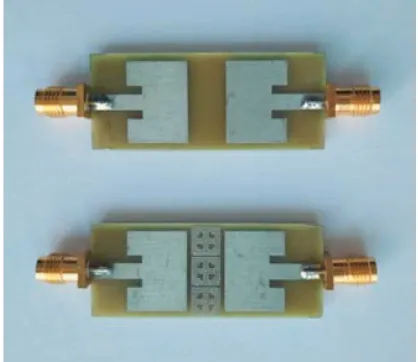
Figure 11. Fabricated prototype of MIMO antenna without and with proposed E-SMLUC-EBG.
Frequency (GHz)
4.0 4.5 5.0 5.5 6.0 6.5 7.0
S11/S21 (dB
)
-60 -50 -40 -30 -20 -10 0
S11 without E-SMLUC-EBG S21 withE-SMLUC-EBG S11 with E-SMLUC-EBG S21 without E-SMLUC-EBG
Figure 12. Measured reflection coefficient and transmission coefficient of MIMO antenna with and without E-SMLUC-EBG.
4. IMPLEMENTATION OF H-PLANE MEANDER LINE EBG (H-SMLUC-EBG) IN MUTUAL COUPLING REDUCTION OF H-COUPLED MIMO ANTENNA FOR WLAN
H-plane Spiro Meander Line Uniplanar Compact EBG (HSMLUC-EBG) as shown in Figure 14 has been created by modifying the E-SMLUC-EBG. Dimension of the unit cell of modified structure (H-SMLUC-EBG) by increasing the length of spiral line of E-SMLUC-EBG is shown in Table 5. H-coupling in antenna develops between non-radiating edges, hence the capacitance between antenna and EBG gets decreased. To compensate this, we have increased the length of spiral line so that resonant frequency remains unchanged. Behavior of the combination of three unit cells of the proposed H-SMLUC-EBG has
dB
0 5 10 15 20
0 5 10 15 20
0 5 10 15 20
0
5
10
15
20 0
30
60
90
120
150
180 210
240 270
300
330
dB
0 5 10 15 20
0 5 10 15 20
0 5 10 15 20
0
5
10
15
20 0
30
60
90
120
150
180 210
240 270
300
330
(a) (b)
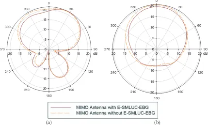
Figure 13. (a) E-plane and (b) H-plane radiation patter of MIMO antenna with and without E-SMLUC-EBG.
Figure 15. Transmission line analysis of three cells of H-SMLUC-EBG structure.
S21 (d
B)
-3 4
25 20 15 10 -5 0
Frequenc
5 6
cy (GHz)
6 7
50 Ohm transmis Transmission line
8 9 ssion line e with EBG
Figure 16. Transmission coefficient S21 graph for three cells of H-SMLUC-EBG structure.
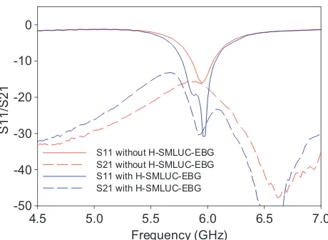
been analyzed using transmission line analysis as shown in Figure 15. It is obvious from Figure 16 that there is significant reduction in transmission coefficient (S21) for the desired band. S21of transmission line with EBG is compared with that of 50 Ω line. Magnetic field in MIMO antenna system gets coupled by non-radiating edges, hence H-SMLUC-EBG has been inserted between the non-radiating edges of antennas to reduce the mutual coupling of MIMO antenna system. H-coupled MIMO antenna system with 7.5 mm gap between non-radiating edges of antennas without and with H-SMLUC-EBG is shown in Figure 17. Reduced surface current in MIMO antenna with EBG compared to that without EBG as shown in Figure 17 clearly displays the mutual coupling reduction. Resonant frequency of the antenna is not disturbed by insertion of EBG, and we get wider bandwidth with 11 dB reductions in transmission coefficient at 5.8 GHz as shown in Figure 18. Reduction of correlation coefficient is shown in Figure 19. Measured reflection coefficients and transmission coefficients of MIMO antenna with and without the proposed EBG are in good match with simulated results. Figure 20 shows a photograph of the fabricated structure, and we get 14.7 dB reductions in mutual coupling with a small shift in frequency at 5.91 GHz after measurement as shown in Figure 21. This frequency shift may be due to fabrication and measurement imperfections. E-plane andH-plane radiation patterns of MIMO antenna are also not affected by the insertion of H-SMLUC-EBG as shown in Figure 22.
Table 5. Optimized values of parameters of unit cell of H-SMLUC-EBG.
Parameters Optimized Values (mm) Parameters Optimized Values (mm)
L1 6 N 0.9
L2 6 P 1.3
L3 5.2 w 0.2
L4 4 g 0.2
M 0.9 S 0.7
5. IMPLEMENTATION OF E-SMLUC-EBG AND H-SMLUC-EBG IN MUTUAL
COUPLING REDUCTION OF 2×2 MIMO ANTENNA SYSTEM FOR WLAN
(a)
(b)
Figure 17. Surface current of H-coupled MIMO antenna for WLAN, (a) without EBG and (b) with H-SMLUC-EBG showing reduced coupling in MIMO antenna.
Frequency (GHz)
4.5 5.0 5.5 6.0 6.5 7.0
S11/S21
-40 -30 -20 -10 0
S11 Withot EBG S21 without EBG S11 with EBG S21 with EBG
Figure 18. Simulated reflection coefficient and transmission coefficient of H-coupled MIMO antenna with and without proposed H-SMLUC-EBG.
Frequency
5.6 5.8 6.0 6.2 6.4
C
o
rre
la
ti
o
n
c
o
e
ffic
ie
n
t
0.0 0.2 0.4 0.6 0.8 1.0 1.2
MIMO Antenna without EBG MIMO Antenna with EBG
Figure 19. Comparison of correlation coef-ficient of H-coupled MIMO antenna with and without proposed H-SMLUC-EBG structure.
reduce E-coupling between antennas 1 and 3, and antennas 2 and 4. Likewise, two combinations of three unit cells H-SMLUC-EBG are placed between non-radiating edges to reduce H-coupling between antennas 1 and 2, and antennas 3 and 4.
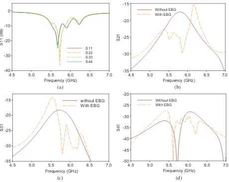
Surface current in Figure 23 shows reduction in mutual coupling in bothE andH planes. Return losses of antenna change slightly with the insertion of EBGs as shown in Figure 24(a). Figures 24(b), (c) and (d) demonstrate that there is 12 dB reduction inS21, i.e., coupling inH-plane and 15 dB reduction inS31, i.e., coupling inE-plane at 5.8 GHz. S41is not very much affected by the insertion of EBGs. This work has been compared with previous works, and we can see that it provides better mutual coupling reduction in both E and H planes with very small edge to edge distance between adjacent antennas.
-Figure 20. Fabricated prototype of MIMO antenna without and with H-SMLUC-EBG.
Frequency (GHz)
4.5 5.0 5.5 6.0 6.5 7.0
S11/S21
-50 -40 -30 -20 -10 0
S11 without H-SMLUC-EBG S21 without H-SMLUC-EBG S11 with H-SMLUC-EBG S21 with H-SMLUC-EBG
Figure 21. Measured reflection and transmission coefficient of MIMO antenna with and without H-SMLUC-EBG.
0 10 20 0
10 20
0 10
20
0
10
20 0
30
60
90
120
150 180
210 240
270 300
330
0 10 2 0 0
10 20
0 10
20
0
10
20 0
30
60
90
120
150 180
210 240
270 300
330
(a) (b)
Figure 22. (a) E-plane and (b) H-plane radiation patter of MIMO antenna with and without H-SMLUC-EBG.
(a) (b)
Figure 23. 2 ×2 Microstrip patch MIMO antenna for WLAN, (a) without EBG (b) with E and H-SMLUC-EBG and Surface current showing reduced coupling in 2×2 MIMO antenna with proposed EBG.
Frequency (GHz)
4.5 5.0 5.5 6.0 6.5 7.0
S11 (dB)
-40 -30 -20 -10 0
S11 S22 S33 S44
Frequency (GHz)
4.5 5.0 5.5 6.0 6.5 7.0
S21
-35 -30 -25 -20 -15
Without EBG With EBG
Frequency (GHz)
4.5 5.0 5.5 6.0 6.5 7.0
S31
-35 -30 -25 -20
-15 without EBG With EBG
Frequency (GHz)
4.5 5.0 5.5 6.0 6.5 7.0
S4
1
-50 -45 -40 -35 -30 -25 -20
Without EBG With EBG
(a) (b)
(c) (d)
Table 6. Performance of the proposed structure compared with previous reported designs.
Ref. Technique
Substrate dielectric
constant (εr)
Centre frequency
(GHz)
Edge to edge distance
Isolation improvement
(in dB)
[1] compact waveguide
metamaterials 2.2 2.45 0.093λ0
18 (E-plane) 9 (H-plane)
[2] Meanderline resonator 4.4 2.8 0.056λ0 8–10 (H-plane)
[3] Cross-like EBG 4.4 5.6 λ0 20 (E-plane)
[4] Mushroom-like EBG 4.4 5.8 0.58λ0 23 (E-plane)
[5]
EBG structure with a double folded bend
connecting bridge
4.6 2.4 0.47λ0 17 (E-plane)
[6]
U-shaped defective ground structure with
inverted U-shaped resonator
4.4 2.45 0.24λ0 20 (E-plane)
[7]
Hilbert-shaped complementary Electric
inductive-capacitive resonator based
metamaterial
2.65 3.5 0.12λ0 9.7 (H-plane)
[8]
slot combined complementary split ring resonator
4.2 3.7 0.5λ0 19(E-plane)
This
work Spiro-Meander line EBG 4.4 5.8 0.14λ0
19 (E-plane) 11(H-plane)
better in the proposed work. Additionally, the proposed work uses a low cost dielectric material, so it is also cost effective.
6. CONCLUSION
REFERENCES
1. Ou Yang, J., F. Yang, and Z. M. Wang, “Reducing mutual coupling of closely spaced microstrip MIMO antennas for WLAN application,” IEEE Antennas And Wireless Propagation Letters, Vol. 10, 310–313, 2011.
2. Qamar, Z. and H. C. Park, “Compact waveguided metamaterials for suppression of mutual coupling in microstrip array,” Progress In Electromagnetics Research, Vol. 149, 183–192, 2014.
3. Ghosh, J., S. Ghosal, D. Mitra, and S. R. B Chaudhuri, “Mutual coupling reduction between closely placed microstrip patch antenna using meander line resonator,”Progress In Electromagnetics Research Letters, Vol. 59, 115–122, 2016.
4. Assimonis, S. D., T. V. Yioultsis, and C. S. Antonopoulos, “Computational investigation and design of planar EBG structures for coupling reduction in antenna applications,” IEEE Transactions on Magnetics, Vol. 48, No. 2, 771–774, February 2012.
5. Islam, M. T. and Md. Shahidul Alam, “Compact EBG structure for alleviating mutual coupling between patch antenna array elements,”Progress In Electromagnetics Research, Vol. 137, 425–438, 2013.
6. Ghosh, C. K., B. Mandal, and S. K. Parui, “Mutual coupling reduction of a dual-frequency microstrip antenna array by using U-shaped DGS and inverted U-shaped microstrip resonator,”
Progress In Electromagnetics Research C, Vol. 48, 61–68, 2014.
7. Xu, H. X., G. M. Wang, and M. Q. Qi, “Hilbert-shaped magnetic waveguided metamaterials for electromagnetic coupling reduction of microstrip antenna array,”IEEE Transactions on Magnetics, Vol. 49, No. 4, 1526–1529, 2013.
8. Qamar, Z., L. Riaz, M. Chongcheawchamnan, S. A. Khan, and M. F. Shafique, “Slot combined complementary split ring resonators for mutual coupling suppression in microstrip phased arrays,”
IET Microw. Antennas Propag., Vol. 8, No. 15, 1261–1267, 2014.
9. Sharawi, M. S., A. B. Numan, and D. N. Aloi, “Isolation improvement in a dual-band dual-element MIMO antenna system using capacitively loaded loops,” Progress In Electromagnetics Research, Vol. 134, 247–266, 2013.
10. Zhang, J., G. Ci, Y. Cao, N. Wang, and H. Tian, “A wide band-gap slot fractal UC-EBG based on moore space-filling geometry for microwave application,”IEEE Antennas and Wireless Propagation Letters, Vol. 16, 33–37, 2017.