Mutual Coupling Reduction in Microstrip Array Antenna
by Employing Cut Side Patches and EBG Structures
Bahare Mohamadzade1, *, Ali Lalbakhsh2, Roy B. V. B. Simorangkir3, Alireza Rezaee4, and Raheel M. Hashmi2
Abstract—This paper presents the simultaneous application of Minkowski fractal geometry and EBG structures for mutual coupling reduction in microstrip array antennas for the first time. In this approach, a modified version of Minkowski fractal geometry is applied on the patch elements, and at the same time 1D electromagnetic bandgap (EBG) structures, composed of 4 EBG elements, are placed between the array elements in a very close distance. Unlike many other coupling reduction methods, which have at least one of the issues of gain reduction or complex fabrication, the proposed method does need any via or double-sided etching and slightly increases the gain of the antenna, while an excellent reduction level of 22.7 dB has been achieved. To verify the concept, 2 array antennas with the spacing of λ0 and
λ0/3 were fabricated and tested, showing very good agreement between predicted and measured results.
1. INTRODUCTION
High-gain antennas are highly desirable in long-distance communications such as satellite-terrestrial links and radar systems because of their highly-directive radiation patterns and their high signal to noise ratio. Perhaps the most traditional high-gain antennas are reflector antennas and horn antennas; however, their large non-planar configurations are not desired in space limited applications. Array antennas do not necessarily have such volumetric constraints, but they can become laterally oversized, due to large distance between array elements to avoid mutual coupling. Microstrip array antennas are one of the most attractive arrays because of their high efficiency, low weight, easy manufacture, and low cost [1]. They generally comprises several low-gain patch antennas arranged to form an array antenna. In many applications, such as wide-angle scanning required in satellite communication systems, the electrical spacing between the array elements needs to be minimal, resulting in unwanted mutual coupling between array elements, leading to degraded radiation efficiency [2]. Moreover, mutual coupling deteriorates the active input impedance of each array and causes scan blindness [3].
To overcome this problem in microstrip array antennas, various methods, such as Split-Ring Resonators (SRR) [4], concave patches [5], waveguide-based metasurfaces [6], and defected ground structures (DGS) [7] have been presented. Although these techniques may provide noticeable mutual coupling reduction, they may have some drawbacks. The replacement of conventional patches with concave patches can slightly improve the mutual coupling through a straightforward approach. However, this approach slightly reduces the gain of each element, due to the reduction of effective aperture of each element [5].
In order to achieve a greater reduction (about 10 dB) in mutual coupling, without affecting the gain of the antenna, SRR can be used [4]. The limitation associated to this method is the complex
Received 7 October 2019, Accepted 22 January 2020, Scheduled 4 February 2020
* Corresponding author: Bahare Mohamadzade ([email protected]).
180 Mohamadzade et al.
prototyping for higher frequencies, when the resonators dimensions are extremely sensitive, and any tolerance in fabrication can affect the resonance frequency. Another approach to achieve a good level mutual coupling isolation at a price of more complex design is the use of DGS. As reported in [7], mutual coupling and gain of the antenna are reduced by around 20 dB and 1.4 dB, respectively by introducing four DGS cells. Unlike most of the above-mentioned techniques which have a by-product of slight gain-reduction, metasurfaces can be utilized for mutual coupling reduction. Metasurfaces are 2D form of metamaterials and have exceptional abilities for controlling electromagnetic waves, which can be used for variety of applications, such as suppressing unwanted coupling effects, beamsteering [6, 8]. In [6], a waveguide based metasurface was designed to exhibit a bandgap with two transmission zeros, which attributed to negative permeability and negative permittivity in the vicinity of magnetic resonance and electric resonance, respectively. The mutual coupling of the antenna was reduced by around 11 dB, while the gain was increased by 0.5 dB, because of the metasurface introduction. In a different approach, artificial intelligence has recently been used in conjunction with electromagnetic simulators to solve some of EM problems including mutual coupling through an evolutionary approach [9–11].
The aim of this study is to propose a new size-effective approach for mutual reduction without sacrificing the gain of the antenna, which does not need double substrate etching or via holes. In the proposed approach for the first time, 1D EBG structures are used in conjunction with a geometrical modification, inspired by Minkowski fractal, on the patch elements. The proposed hybrid technique significantly reduces the number of EBG elements required to remarkably attenuate the mutual coupling between the patch elements by 22.7 dB, with 0.8 dB gain enhancement, reaching up to 5.2 dB. The envelope correlation coefficient of the proposed antenna system is less than 0.03 for 5.2 to 6 GHz, and the antenna efficiency is greater than 40% over the same frequency range. The size of the antenna is 80 mm×150 mm. In addition, unlike [12] our proposed EBG consists of only four cells arranged in one column, resulting in smaller distance between the patches. This low profile antenna, like other low profile planar antennas, has a potential to be fabricated with flexible materials such as antenna based on polydimethylsiloxane and conductive fabric due to its high gain, high efficiency, and low profile [13, 14].
2. ANTENNA CONFIGURATION
2.1. EBG Unit Cell
The use of EBG structures for mutual coupling reduction has been widely investigated, and various types of EBG structures have been proposed for this application [15]. The concept of EBG arises from the optical domain, where photonic crystals can forbid the propagation of light or allow it in certain directions. This feature can be used in suppressing surface-waves and realization of EBG resonator antennas [15–18]. These periodic structures are composed of a metallic or dielectric element, mostly in the form of 2D and 3D structure geometries. The proposed structure in this study is a 1D EBG structure, where 4 elements are arranged along with one axis to suppress the mutual coupling between two patch elements. The proposed EBG structure is easily fabricable, without the need of any vias. The process of designing unit cell is explained as follows.
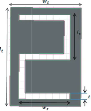
Step 1 (choosing unit cell structure): The EBG unit cell used for mutual coupling reduction is shown in Fig. 1. The idea of using EBG-based unit cells for mutual coupling reduction comes from [18], in which the unit cells are used for improving the bandwidth of Fabry-Perot antennas. The EBG structure can be modelled by an LC equivalent circuit if the periodicity of structure is small compared to the operating wavelength [19]. In order to have a compact unit cell with lower resonant frequency, a slot is added to the square unit cell.
Step 2 (investigating the unit cell band gap): After choosing the explained unit cell, itsS-parameters are studied. The width and length of the slot is optimized through HFSS modelling simulator to tune the resonance at 5.6 GHz, where the highest return loss is achieved.
Figure 1. The EBG unit cell. Figure 2. The schematic of patches in proposed microstrip antenna.
Table 1. Dimensions of EBG unit cell (in mm).
wt lt ws ls t
16 14.2 10.4 6 1.2
2.2. Patch Configuration
In array structures, there is an electromagnetic interaction between patch elements, which is stronger across the adjacent sides. The effect of electromagnetic interaction between the elements can be reduced by applying a Minkowski-like fractal geometry on the patch as shown in Fig. 2.
Minkowski fractal was proposed by Hermann Minkowski in 1906 for the first time and brought into electromagnetic community in late 1990, and since then it has been used for modifying electromagnetic and microwave components [20]. In the proposed patch configuration, cuts are small compared to the patch size and would not affect the antenna performance. The shape and size of cuts are shown in Fig. 2. The introduction of the EBG structure along with the patch modification is depicted in Fig. 3.
(a) (b)
182 Mohamadzade et al.
3. SIMULATION RESULTS
The proposed antenna is implemented on an FR4 substrate with a thickness of 1.6 mm, relative permittivity of 4.8, and loss tangent of 0.015. The resonance frequency of the antenna is around 5.6 GHz suitable for WLAN applications. The proposed antenna is fed by two coaxial probes (see Fig. 3) and simulated using HFSS 14. The dimensions of the patches are listed in Table 2.
Table 2. Dimensions of the patches (in mm).
Ws Ls wp lp x y d 80 150 33.5 37.5 10 18 52
In order to give a better insight into the individual effects of the EBG structures as well as the modified patch elements, the mutual coupling of the system is analysed separately. As shown in Fig. 4, each individual technique has been effective in reducing the mutual coupling, showing 4 dB and 12 dB for the case of only EBG and only patch modifications, respectively, when the two patches are separated by λ0 (52 mm). In the next step, both techniques are used at the same time to achieve greatly higher isolation level.
Figure 5 shows the mutual coupling for the conventional patches without the EBG structures and the proposed hybrid method (EBG and modified patches) for two different distances ofλ0 (52 mm) and
λ0/3 (19 mm) between the two patches. As can be seen from this figure, the mutual coupling between patches has been significantly reduced from 24 dB to about 44 dB for the case of λ0/3 and from 26 dB to about 48 dB for the case of λ0 distance between the two patches.
To further investigate the effects of EBG and cut patches, individually, the current distribution are shown in Fig. 6. As depicted in Fig. 6, there is strong current induced on the left-side patch, as a result of the unwanted coupling between the patches. This coupling is decreased by the introduction of the EBG structure, resulting in lower current density on the left-side patch, as shown in Fig. 6(b). This current density is then further reduced, when the fractal geometry is applied on the patches as depicted in Fig. 6(c).
Envelop correlation of the conventional and proposed antennas with a separation of λ0/3 is shown in Fig. 7. In the antenna with modified patches and EBG cells, the ECC is less than 0.03 throughout the entire operating frequency band. In addition, as shown in Fig. 8, the antenna gain and efficiency are improved in the proposed structure compared to conventional antenna.
Figure 4. Simulated Sparameter of the antenna with cut side patches and EBG structure at the distance ofλ0.
Figure 5. SimulatedSparameter of conventional and proposed antennas at two distances of
(a)
(b)
(c)
Figure 6. Surface current distributions at 5.6 GHz, (a) without EBG and cuts, (b) with EBG without cuts, (c) with EBG and cuts.
Figure 7. Simulated ECC of conventional and proposed antennas at distances ofλ0/3(d1).
Figure 8. Simulated peak gain and radiation efficiency of conventional and proposed antennas at distances of λ0/3(d1).
4. MEASUREMENT RESULTS
184 Mohamadzade et al.
Figure 9. Measurement results of conventional and proposed antennas at two distances of λ0/3(d1) and λ0(d2).
0
-10
-20
-30
-40
-50
-60 5.2 5.3
S
S-Parameters
5.4 5.5
Frequency (GHz) S21
S11
5.7 5.6 5.8
Measurement Simulation
8 5.9 6.0
Figure 10. Simulated and measurement results of conventional and proposed antennas at distance of
λ0/3.
(a) (b)
Figure 12. Prototypes of cut side microstrip patches with EBG structure at two different distances (λ0, λ0/3).
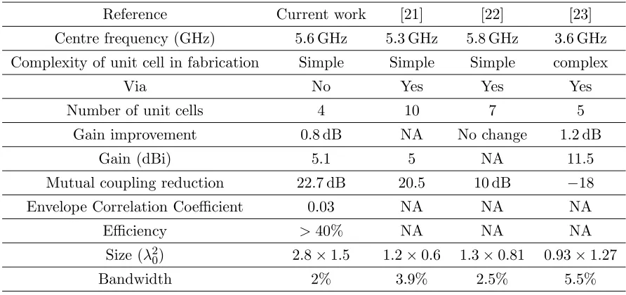
Table 3. Comparison of the proposed antenna characterization with previous works.
Reference Current work [21] [22] [23]
Centre frequency (GHz) 5.6 GHz 5.3 GHz 5.8 GHz 3.6 GHz
Complexity of unit cell in fabrication Simple Simple Simple complex
Via No Yes Yes Yes
Number of unit cells 4 10 7 5
Gain improvement 0.8 dB NA No change 1.2 dB
Gain (dBi) 5.1 5 NA 11.5
Mutual coupling reduction 22.7 dB 20.5 10 dB −18
Envelope Correlation Coefficient 0.03 NA NA NA
Efficiency >40% NA NA NA
Size (λ2
0) 2.8×1.5 1.2×0.6 1.3×0.81 0.93×1.27
Bandwidth 2% 3.9% 2.5% 5.5%
a combination of EBG structures and fractal geometry, for the separation distance of 19 mm (top figure) and 52 mm (bottom figure). The S-parameters are measured using Agilent-N5230A PNA-L series network analyser and are shown in Fig. 9. It is depicted that the measurement results are in good agreement with the predicted results from simulations (see Fig. 10). The radiation patterns in
E-plane and H-plane of the array are presented in Fig. 11. As expected, radiation characterization after reduction of mutual coupling in the antenna is enhanced, and gain of the structure is improved by 0.8 dB.
186 Mohamadzade et al.
5. CONCLUSION
This paper presents an effective mutual coupling reduction method for patch arrays, in which two different techniques are combined, for the first time, to achieve a significant reduction level of around 22.7 dB, through a cost and size-effective mechanism. In this method, Minkowski-like fractal geometry is applied on the patch elements, and simultaneously 1D EBG elements are placed very close to the patches. Unlike most of mutual reduction methods, the proposed approach not only does not reduce the gain, but also causes 0.8 dB increase in the gain of the antenna.
REFERENCES
1. Ghosh, C. and S. K. Parui, “Reduction of mutual coupling between E-shaped microstrip antennas by using a simple microstrip I-section,”Microwave and Optical Technology Letters, Vol. 55, No. 11, 2544–2549, 2013.
2. Chaloun, T., Ch. Waldschmidt, and W. Menzel, “Wide angle scanning cavity antenna element for mobile satcom applications at Ka band,”10th European Conference on Antennas and Propagation (EuCAP), 1–5, April 2016.
3. Shen, J., Z. Xu, and T. Zheng, “Design and mutual coupling analysis on wideband wide-angle scan step constant tapered slot antenna array,” IEEE International Conference on Ultra-Wideband, Vol. 2, 1–4, September 2010.
4. Bait-Suwailam, M. M., O. F. Siddiqui, O. M. Ramahi, et al., “Mutual coupling reduction between microstrip patch antennas using slotted-complementary split-ring resonators,”IEEE Antennas and Wireless Propagation Letters, Vol. 9, 876–878, 2010.
5. Mohanna, Sh., A. Farahbakhsh, and S. Tavakoli, “Mutual coupling reduction in two-dimensional array of microstrip antennas using concave rectangular patches,” Journal of Telecommunications, Vol. 2, No. 2, 64–69, 2010.
6. Cheng, W. G., G. M. Wang, J. G. Liang, X. J. Gao, and L. Zhu, “Novel ultra-compact two-dimensional waveguide-based metasurface for electromagnetic coupling reduction of microstrip antenna array,”International Journal of RF and Microwave Computer-Aided Engineering, Vol. 25, 789–794, 2015.
7. Ahmed, M. I., A. Sebak, and E. A. Abdallah, “Mutual coupling reduction using defected ground structure (DGS) for array applications,”2012 15 International Symposium on Antenna Technology and Applied Electromagnetics, 1–5, Toulouse, 2012.
8. Afzal, M. U., A. Lalbakhsh, and K. P. Esselle, “Electromagnetic-wave beam-scanning antenna using near-field rotatable graded-dielectric plates,”Journal of Applied Physics, Vol. 124, No. 23, 234901, 2018.
9. Lalbakhsh, A., M. U. Afzal, and K. P. Esselle, “Multiobjective particle swarm optimization to design a time-delay equalizer metasurface for an electromagnetic band-gap resonator antenna,”
IEEE Antennas and Wireless Propagation Letters, Vol. 16, 912–915, 2016.
10. Pirhadi, A., M. H. Rahmani, and A. Mallahzadeh, “Shaped beam array synthesis using particle swarm optimisation method with mutual coupling compensation and wideband feeding network,”
IET Microwaves, Antennas &Propagation, Vol. 8, No. 8, 549–550, February 14, 2014.
11. Jamshidi, M. B., et al., “A novel neural-based approach for design of microstrip filters,” AEU — International Journal of Electronics and Communications, 152847, 2019.
12. Mohamadzade, B. and M. Afsahi, “Mutual coupling reduction and gain enhancement in patch array antenna using a planar compact electromagnetic band gap (EBG) structures,” IET Microwaves, Antennas & Propagation, Vol. 11, No. 12, 1719–1725, 2017.
13. Mohamadzade, B., R. M. Hashmi, R. B. V. B. Simorangkir, R. Gharaei, S. Ur Rehman, and Q. H. Abbasi, “Recent advances in fabrication methods for flexible antennas in wearable devices: State of the art,” Sensors, Vol. 19, No. 10, 2312, 2019.
realization of robust passive and active flexible wearable antennas,” IEEE Access, Vol. 6, 48102– 48112, 2018.
15. Olule, L., B. Kasi, N. Kumar, et al., “An aperture coupled metamaterial mushroom antenna for operation at WLAN frequency,”Microwave and Optical Technology Letters, Vol. 58, No. 11, 2692– 2696, 2016.
16. Farahani, H. S., M. Veysi, M. Kamyab, and A. Tadjalli, “Mutual coupling reduction in patch antenna arrays using a UC-EBG superstrate,” IEEE Antennas and Wireless Propagation Letters, Vol. 9, 57–59, 2010.
17. Mousavi Razi, Z., P. Rezaei, and A. Valizade, “A novel design of Fabry-Perot antenna using metamaterial superstrate for gain and bandwidth enhancement,”AEU — International Journal of Electronics and Communications, Vol. 69, No. 10, 1525–1532, 2015.
18. Naderi, M., F. B. Zarrabi, F. S. Jafari, and S. Ebrahimi, “Fractal EBG structure for shielding and reducing the mutual coupling in microstrip patch antenna array,” AEU — International Journal of Electronics and Communications, Vol. 93, 261–267, 2018.
19. Zheng, Q., Y. Fu, and N. Yuan, “A novel compact spiral electromagnetic band-gap structure,”
IEEE Trans. Antennas Propag., Vol. 56, No. 6, 1656–1660, 2008.
20. Lalbakhsh, A., A. A. L. Neyestanak, and M. Naser-Moghaddasi, “Microstrip hairpin bandpass filter using modified Minkowski fractal-shape for suppression of second harmonic,” IEICE Transactions on Electronics, Vol. 95, No. 3, 378–381, 2012.
21. Veeramani, A., J. Vijayakrishnan, A. Arezomand, et al., “Compact S-shaped EBG structures for reduction of mutual coupling,” Fifth International Conference on Advanced Computing &
Communication Technologies, Haryana, India, Febrarury 2015.
22. Abushamleh, S., H. Al-Rizzo, A. Abbosh, et al., “Mutual coupling reduction between two patch antennas using a new miniaturized soft surface structure,” IEEE AP-S Dig., Orlando, USA, July 2013.