Hardware Implementation From High-Level Dataflow
Programs
Khaled Jerbi, Micka¨
el Raulet, Olivier D´
eforges, Mohamed Abid
To cite this version:
Khaled Jerbi, Micka¨
el Raulet, Olivier D´
eforges, Mohamed Abid.
Automatic Generation
Of Optimized And Synthesizable Hardware Implementation From High-Level Dataflow
Pro-grams.
VLSI Design, Hindawi Publishing Corporation, 2012, 2012, pp.Article ID 298396.
<
10.1155/2012/298396
>
.
<
hal-00724403
>
HAL Id: hal-00724403
https://hal.archives-ouvertes.fr/hal-00724403
Submitted on 20 Aug 2012
HAL
is a multi-disciplinary open access
archive for the deposit and dissemination of
sci-entific research documents, whether they are
pub-lished or not.
The documents may come from
teaching and research institutions in France or
abroad, or from public or private research centers.
L’archive ouverte pluridisciplinaire
HAL
, est
destin´
ee au d´
epˆ
ot et `
a la diffusion de documents
scientifiques de niveau recherche, publi´
es ou non,
´
emanant des ´
etablissements d’enseignement et de
recherche fran¸
cais ou ´
etrangers, des laboratoires
publics ou priv´
es.
Volume 2012, Article ID 298396,14pages doi:10.1155/2012/298396
Research Article
Automatic Generation of Optimized and Synthesizable Hardware
Implementation from High-Level Dataflow Programs
Khaled Jerbi,
1, 2Micka¨el Raulet,
1Olivier D´eforges,
1and Mohamed Abid
21IETR/INSA. UMR CNRS 6164, 35043 Rennes, France
2CES Laboratory, National Engineering School of Sfax, 3038 Sfax, Tunisia
Correspondence should be addressed to Khaled Jerbi,[email protected]
Received 16 December 2011; Revised 18 April 2012; Accepted 15 May 2012 Academic Editor: Maurizio Martina
Copyright © 2012 Khaled Jerbi et al. This is an open access article distributed under the Creative Commons Attribution License, which permits unrestricted use, distribution, and reproduction in any medium, provided the original work is properly cited. In this paper, we introduce the Reconfigurable Video Coding (RVC) standard based on the idea that video processing algorithms can be defined as a library of components that can be updated and standardized separately. MPEG RVC framework aims at providing a unified high-level specification of current MPEG coding technologies using a dataflow language called Cal Actor Language (CAL). CAL is associated with a set of tools to design dataflow applications and to generate hardware and software implementations. Before this work, the existing CAL hardware compilers did not support high-level features of the CAL. After presenting the main notions of the RVC standard, this paper introduces an automatic transformation process that analyses the non-compliant features and makes the required changes in the intermediate representation of the compiler while keeping the same behavior. Finally, the implementation results of the transformation on video and still image decoders are summarized. We show that the obtained results can largely satisfy the real time constraints for an embedded design on FPGA as we obtain a throughput of 73 FPS for MPEG 4 decoder and 34 FPS for coding and decoding process of the LAR coder using a video of CIF image size. This work resolves the main limitation of hardware generation from CAL designs.
1. Introduction
User requirements of high quality video are growing which causes a noteworthy increase in the complexity of the algo-rithms of video codecs. These algoalgo-rithms have to be imple-mented on a target architecture that can be hardware or soft-ware. In 2007, the notion of Electronic System Level Design (ESLD) has been introduced in [1] as a solution to decrease the time to market using high-level synthesis which is an automatic compilation of high-level description into a low-level one called register transfer low-level (RTL). The high-low-level description is governed by models of computation which are the rules defining the way data is transferred and processed. Many solutions were developed to automate the hardware generation of complex algorithms using ESLD. Synopsys developed a C to gate compiler called synphony [2]. Mentor Graphics also created a C to HDL compiler called Cata-pult C [3,4]. For their NIOS II, Altera introduces C2H as a converter from C to HDL [5,6]. To extend Matlab for hard-ware generation from functional blocks, Mathworks created
a hardware generator for FPGA design [7]. In the university research field, STICC laboratory in France developed a high-level synthesis tool called GAUT that extracts parallelism and generates VHDL code from a pure C description [8,9]. The common point between all previously quoted tools is the fact that they are application-specific generators which means that they are not always efficient on an entire multi-component system description.
In this context, CAL [10] was introduced in the Ptolemy II project [11] as a general-use dataflow target agnostic lang-uage based on the dataflow Process Network (DPN) Model of Computation [12] related to the Kahn Process Network (KPN) [13]. The MPEG community standardized the RVC-CAL language in the MPEG RVC (Reconfigurable Video Coding) standard [14]. This standard provides a framework to describe the different functions of a codec as a network of functional blocks developed in RVC-CAL and called actors. Some hardware compilers of RVC-CAL were developed but their limitation is the fact that they cannot compile high-level
structures of the language so these structures have to be man-ually transformed.
In [15], we presented an original functional method to quicken the HDL generation using a software platform for rapid design and validation of a high complexity dataflow architecture but going from high to low-level representation used to be manual. Therefore, we proposed to add automatic transformations to make any RVC-CAL design synthesizable. This paper extends a preliminary work presented in [16] by introducing efficient optimizations and their impact on the area and time consumption of the design. The transform-ation tool analyzes the RVC-CAL code and performs the required transformations to obtain synthesizable code what-ever the complexity of the considered actor. InSection 2, we explain the main advantages of using MPEG RVC standard for signal processing algorithms and the key notions of the RVC-CAL language and its behavioral structures and mech-anisms. The proposed transformation process is detailed in Section 4 and finally hardware implementation results of MPEG4 Part2 decoder and LAR codec are presented in Sections5and6.
2. Background
Since the beginning of ISO/IEC/WG11 (MPEG) in 1988 with the appearance of MPEG-1, many video codecs have been developed (MPEG-4 part2, MPEG SVC, MPEG AVC, HEVC, etc.) with an increasing complexity and so they take longer time to be produced. In addition, every standard has a set of profiles depending on the implementation target or the user specifications. Consequently, it became a tough task for standard communities to develop, test, and stand-ardize a decoder at any given time. Moreover, the standards specification is monolithic which makes it harder to reuse or update some existing algorithms. This ascertainment origi-nated a new conception methodology standard called Recon-figurable Video Coding introduced by MPEG.
In the following, we present an overview of MPEG RVC standard and associated tools and frameworks, we also pre-sent the main features of CAL actor language and the limita-tions that motivated this work.
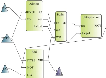
2.1. MPEG RVC. RVC presents a modular library of elemen-tary components (actors). The most important and attractive features of RVC are reconfigurability and flexibility. An RVC design is a dataflow directed graph with actors as vertices and unidirectional FIFO channels as edges. An example of a graph is shown inFigure 1.
Actually, defining video processing algorithms using ele-mentary components is very easy and rapid with RVC since every actor is completely independent from the rest of the other actors of the network. Every actor has its own schedu-ler, variables, and behavior. The only communication of an actor are its input ports connected to the FIFO channels to check the presence of tokens and as explained later an inter-nal scheduler is going to allow or not the execution of ele-mentary functions called actions depending on their cor-responding firing rules (seeSection 3). Thus, RVC insures concurrency, modularity, reuse, scalable parallelism, and
encapsulation. In [17], Janneck et al. show that, for hardware designs,RVC standard allows a gain of 75%of development timeand considerably reduces the number of lines compared with the manual HDL code. To manage all the presented concepts of the standard, RVC presents a framework based on the use of the following.
(i) A subset of the CAL actor language called RVC-CAL that describes the behavior of the actors (see details inSection 2.2).
(ii) A language describing the network called FNL (Func-tional unit Network Language) that lists the actors, the connections and the parameters of the network. FNL is an XML dialect that allows a multilevel des-cription of actors hierarchy which means that a func-tional unit can be a composition of other funcfunc-tional units connected in another network.
(iii) Bitstream syntax Description Language (BSDL) [18, 19] to describe the structure of the bitstream. (iv) An important Video Tool Library (VTL) of actors
containing all MPEG standards. This VTL is under development and it already contains 3 profiles of MPEG 4 decoders (Simple Profile, Progressive High Profile and Constrained Baseline Profile).
(v) Tools for edition, simulation, validation and auto-matic generation of implementations:
(a) open DF framework [20] is an interpreter infrastructure that allows the simulation of hierarchical actors network. Xilinx contributed to the project by developing a hardware com-piler called OpenForge (available at http:// openforge.sourceforge.net/) [21] to generate HDL implementations from RVC-CAL designs. (b) open RVC-CAL Compiler (Orcc) (available at http://orcc.sourceforge.net/) [19] is an RVC-CAL compiler under development. It compiles a network of actors and generates code for both hardware and software targets. Orcc is based on works on actors and actions analysis and synthesis [22, 23]. In the front-end of Orcc, a graph network and its associated CAL actors are parsed into an abstract syntax tree (AST) and then transformed into an inter-mediate representation that undergoes typing, semantic checks and several transformations in the middle-end and in the back-end. Finally, pretty printing is applied on the resulting IR to generate a chosen implementation language (C, Java, Xlim, LLVM, etc.).
At this level, the question is thatwhy RVC-CAL and not C? Actually, a C description involves not only the specifica-tion of the algorithms but also the way inherently parallel computations are sequenced, the way data is exchanged throw inputs and outputs, and the way computations are mapped. Recovering the original intrinsic properties of the algorithms by analyzing the software program is impossible.
Address BTYPE BTYPE BTYPE RA RA MV MV WA WA halfpel halfpel RD RD WD Buffer Add VID VID MOT MOT TEX TEX Interpolation
Figure1: Graph example. Block diagram of the motion compensation of an MPEG 4 part 2 decoder.
FIFO FIFO FIFO FIFO FIFO Actor Actor Actor Actions State Consume/produce tokens and modify internal states
Actions are implemented sequentially and they can
be sequenced
Figure2: CAL actor model.
In addition, the opportunities for restructuring transforma-tions on imperative sequential code are very limited com-pared to the parallelization potential available on multi-core platforms. For these reasons, RVC adopted the CAL language for actors specification. The main notions of this language are presented below.
2.2. CAL Actor Language. The execution of an RVC-CAL code is based on the exchange of data tokens between com-putational entities (actors). Each actor is independent from the others since it has its own parameters and finite state machine if needed. Actors are connected to form an appli-cation or a design, this connection is insured by FIFO chan-nels. Executing an actor is based onfiringelementary func-tions calledactions. This action firing may change the state of the actor in case of an FSM. An RVC-CAL dataflow model is shown in the network ofFigure 2.
Figure 3presents an example of a CAL actor realizing the sum between two tokens read from its two input ports.
Like in VHDL, an actor definition begins by defining the I/O ports and their types then actions are later listed. An action begins also by defining the I/O ports it uses from the list of ports of the actor and this definition includes the number of tokens this action have to find in the FIFO to be
fireable. In the “sum” actor, the internal scheduler allows action “add” only when there is at least one token in the FIFO of port “INPUT1” and one token in the FIFO of port “INPUT2” and this property explains how an actor can be totally independent and can neither read nor modify the state of any other actor. Of course, an actor may contain any number of actions that can be governed by an internal finite state machine. At a specific time two or more actions may have the required conditions to be fired so the notion of priority was introduced (see details inSection 3).
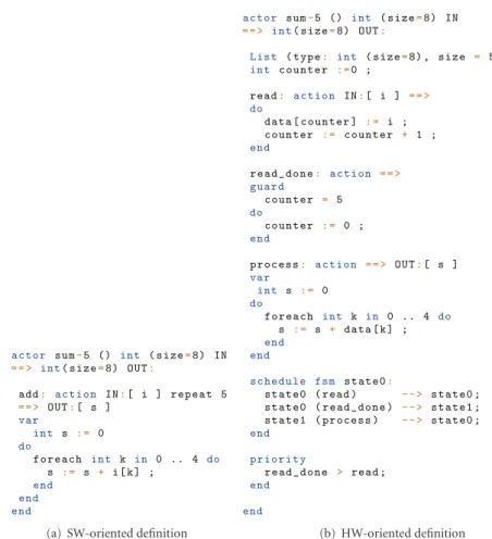
For the same behavior, an actor may be defined in dif-ferent ways. Let us consider the “sum-5” actor of Figure 4 that reads 5 tokens in a port “IN,” computes their sum and produces the result in a port “OUT.”
InFigure 4(a), the required algorithm is defined in only one action. The condition of 5 required tokens is expres-sed by the instruction “repeat 5.” Action “add” fires by con-suming the 5 tokens from the FIFO into an internal buffer “I.” After data storage, the algorithm of the action is applied. Finally the action firing finishes by writing the result in the port “OUT”.
Such description is very fast to develop and implement on software targets but for hardware implementations a multitoken read is not appropriate. This is the reason of
actor sum ()
(int size=8) INPUT1 , (int size=8) INPUT2 = = > int( size=8) OUTPUT:
add: action INPUT1:[ i1 ] , INPUT2 [ i2 ] = = > OUTPUT:[ s ]
var int s do s: = i1 + i2 ; end end
Figure3: Example of sum actor.
actor sum-5 () int ( size=8) IN
= = > int( size=8) OUT:
add: action IN:[ i ] repeat 5
= = > OUT:[ s ] var int s : = 0 do f o r e a c h int k in 0 .. 4 do s : = s + i [ k ] ; end end end
(a) SW-oriented definition
actor sum-5 () int ( size=8) IN
= = > int( size=8) OUT:
List ( type: int ( size=8) , size = 5) data ;
int c o u n t e r : =0 ; read: action IN:[ i ] = = > do data [ c o u n t e r ] : = i ; c o u n t e r : = c o u n t e r + 1 ; end r e a d _ d o n e: action = = > guard c o u n t e r = 5 do c o u n t e r : = 0 ; end p r o c e s s: action = = > OUT:[ s ] var int s : = 0 do f o r e a c h int k in 0 .. 4 do s : = s + data [ k ] ; end end s c h e d u l e fsm state0:
state0 ( read ) - - > state0 ; s ta te 0 ( r e a d _ d o n e ) - - > state1 ; state1 ( process ) - - > state0 ;
end p r i o r i t y r e a d _ d o n e > read ; end end (b) HW-oriented definition
Figure4: Two-way definition example of sum-5 actor behavior.
developing the equivalent monotoken code ofFigure 4(b). In this description, we use a finite state machine to lock the actor in the state “state0.” While counter¡5, only the action “read” can be fired to store tokens one per one in “data” buffer. Once the condition of action “read done” (counter= 5) is true, both of “read” and “read done” actions are fireable. This is why the priority “read done ≻read” is important to keep the determinism of the actor. Finally, the firing of “read done” action involves an FSM update to “state1” where only “process” action can be fired and the actor is back to the initial state.
3. Actor Behavior Formalism
Actor execution is governed by a set of conditions called firing rules. Moreover, during this firing many internal
features of the actor are updated (state, state variables, etc.). All these concepts and behavior evolutions are detailed below. The actor execution, so called firing, is based on the dataflow Process Network (DPN) principle [12] derived from the Kahn Process Network (KPN) [13]. LetΩbe the universe of all tokens values exchanged by the actors and
S= Ω∗, the set of all finite sequences inΩ. We denote the
length of a sequences ∈ Sk by|s|and the empty sequence
byλ. Considering an actor withminputs andnoutputs,Sm
andSnare the set ofm-tuples andn-tuples consumed and
produced. For example,s0=[λ[t0,t1,t2]] ands1=[[t0], [t1]]
are sequences of tokens that belong toS2and we have|s0| =
[0, 3] and|s1| =[1, 1].
3.1. Actor Firing. A dataflow actor is defined with a pair f,Rsuch as:
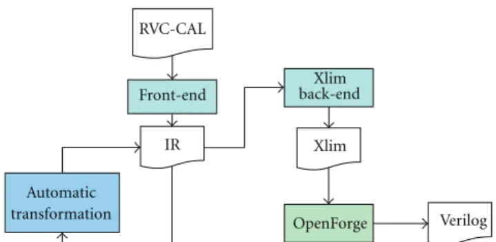
Front-end Xlim back-end Automatic transformation RVC-CAL IR Xlim OpenForge Verilog
Figure5: Automatic transformation localization in Orcc compiling process.
(i) f :Sm → Snis the firing function;
(ii)R⊂Smare the firing rules;
(iii) for allr ∈R,f(r) is finite.
An actor may have N firing rules which are finite sequences ofmpatterns (one for each input port). A pattern is an acceptable sequence of tokens for an input port. It defines the nature and the number of tokens necessary for the execution of at least one action. RVC-CAL also introduces the notion ofguardas additional conditions on tokens values. An example of firing rulerjinS2is
gj,k: [x]|x >0 rj= t0∈gj,k, [t1,t2,t3] , (1)
Equation (1) means that if there is a positive token in the FIFO of the first input port and 3 tokens in the FIFO of the second input port then the actor will select and execute a fire-able action. An action is firefire-able or schedulfire-able iff:
(i) the execution is possible in the current state of the FSM (if an FSM exists);
(ii) there are enough tokens in the input FIFO; (iii) a guard condition returns true.
An action may be included in a finite state machine or untagged making it higher priority than FSM actions.
3.2. Actor Transition. The FSM transition system of an actor is defined withσ0,Σ,τ,≺whereΣis the set of all the states
of the actor,σ0is the initial state,≺is a priority relation and
τ ⊆Σ×Sm×Sn×Σis the set of all possible transitions. A
transition from a stateσ to a stateσ′with a consumption of sequences∈Smand a produced sequences′∈Snis defined
with (σ,s,s′,σ′) and denoted. σ−→s→s′σ′
τ . (2)
To solve the problem of the existence of more than one possible transition in the same state, RVC-CAL introduced the notion of priority relation such as for the transitions
t0,t1 ∈ τ,t0 a higher priority thant1is writtent0 ≻ t1. As
explained in [24] a transitionσ−−→s→s′ σ′ τ is enabled iff: ¬∃σ p−→→τqσ′′∈τ :p∈S∧σ−→s→s′ τ σ ′′≻σ−→s→s′σ′ τ . (3)
This section presented and explained the main RVC-CAL principles. In the next section we present an automatic transformation as a solution to avoid these limitations without changing the overall macrobehavior of the actor.
3.3. Hardware Generation Problematic. A firing rule is called
multitokeniff:∃e∈ |s|:e >1 otherwise it is called a mono-tokenrule. The limitation of OpenForge is the fact that it does not support multitoken rules which are omnipresent in most actors. The observation ofFigure 4shows the incontestable complexity difference between the multitoken (a) and the monotoken (b) code. Moreover, manually changing a CAL code from high-level to low-level by creating the new actions, variables and state machine is contradictory to the main purpose of RVC standard which is the fact that CAL is a target agnostic language so we have to write in CAL the same way for hardware of software implementation. Our work consists in automatically transforming the data read/write processes from multitoken to monotoken while preserving the same actor behavior. All the required actions, variables and finite state machines are created and optimized directly in the Intermediate representation of Orcc compiler. The following section explains the achieved transformation mechanism.
4. Methodology for Hardware Code Generation
As shown in Figure 5, our transformation acts on the IR of Orcc. The HDL implementation is later generated using OpenForge.
4.1. Actor Transformation Principle. Let us consider an actor with a multitoken firing rule r ∈ Sk such as |r| =
[r0,r1,. . .,rk−1], this rule fires a multitoken actionarealizing
the transitionsource−→a
τ targetand
Ithe set of all input ports.
The transformation creates for every input port an internal buffer with read-and-write indexes and clipsrinto a setRof kfiring rules so that:
∀i∈I,∃!ρ∈R: ⎧ ⎪ ⎪ ⎨ ⎪ ⎪ ⎩ ρ:S1−→S0 |r| =1 gρ:IdxWritei−IdxReadi≤szi, (4)
with ρ a monotoken firing rule of an untagged action untaggedi, gρ is the guard of ρ, and szi the size of the
associated internal buffer defined as the closest power of 2 of ri. This guard checks that the buffer contains an empty place
for the token to read. The multitoken action is consequently removed, and newread actionsthat read one token from the internal buffers are created. While reading tokens another firing rule may be validated and causes the firing of an unwanted action. To avoid the nondeterminism of such a case, we use an FSM to put the actor in a reading loop so it can only read tokens. The loop is entered using atransition
actor A () int IN1 , int IN2 , int IN3 = = > int OUT1 , int OUT2:
a: action
in1:[ in1 ] repeat 2 , IN2:[ in2 ] repeat 3 , IN3:[ in3 ] = = >
OUT1:[ out1 ] , OUT2:[ out2 ] repeat 2
do
{ t r e a t m e n t }
end end
Figure6: RVC-CAL code of actor A.
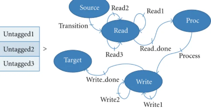
Write Write2 Write1 Process target Read Target Read2 Read1 Source Proc Read3 Transition Untagged1 Untagged2 Untagged3 Write done Read done >
Figure7: Created FSM macroblock.
action realizing the FSM passagesource −−−−−→transitionτ readand has the same priority order of the deleted multitoken action but has no process. The read actions loop in the read state with the transition t = read −−→read
τ read. Then the loop is
exited when all necessary tokens are read using aread done
action and a transition to the process statet′=read−−−−−−→read Done
τ
process ≻t. The treatment of the multitoken action is put in a process action with a transition process −−−−→processτ write. The multitoken outputs are also transformed into a writing loop withwrite actionsthat store data directly in the output FIFO associated with a transitionw = write −−−→writeτ write and awrite doneaction that insures the FSM transitionw′= write−−−−−−→write Doneτ target≻w.
For example, the actorAofFigure 6is defined with
f:S3→S2 with a multitoken firing rule:
r∈S3:r=[[t
0,t1], [t2,t3,t4], [t5]].
Consequently,|r| =[2, 3, 1] which means that there is an action inAthat fires if 2 tokens are present inIN1 port, 3 tokens are present inIN2 and one token is present inIN3. The transformation creates the FSM macroblock ofFigure 7.
4.2. FSM Creation Cases. We consider an example of an actor defined as f :S3 → S2containing the actionsa1··a5 such as
a3 is the only action applying a multitoken firing ruler∈S3.
Creating an FSM only for actiona3 is not appropriate becausea1,a2,a4,a5 will be a higher priority which may not be true. The solution is to create an initial state containing all the actions and add the created FSM macroblock ofa3 (previously presented in Figure 7). The resulting FSM is presented inFigure 8.
We now suppose the same actor scheduled with an initial FSM as shown inFigure 9.
The transition t = S1 −−→s→τs′ S2 is substituted with the macroblock ofa3 as shown inFigure 10.
4.3. Optimizations. To improve the transformation, some optimization solutions were added. In the previously pre-sented transformation method we used the untagged actions to store data in the internal buffers, then we used read actions to peek the required tokens from the internal buffers using R/W indexes and masks. To preserve the schedulability, the action is split into a transition action that contains the firing rule and a process action that applies the algorithm. The proposed optimization consists in making the action reading directly from the internal buffers. The firing rule of the action is transformed as presented in (4) to detect the presence of enough data in the internal buffers. Let us reconsider the basic example of the “sum-5” actor of Figure 4 ofSection 2.2. The transformation explained above and the optimized transformation of this actor are presented in Figure 11. This actor is transformed this way. First an internal buffer and an untagged action are created to store data inside the actor. The input pattern of thereadaction is transformed into a connection to the internal buffer. Every read or write from the internal buffer must be masked to make the modulo of th buffer size since it is circular.
5. RVC Case of Study: MPEG 4 SP Intradecoder
To assess the performance of the previously presented trans-formation, we applied it on the whole MPEG 4 simple profile intradecoder. This choice is explained by the fact that there exists a stable design in the VTL and also because this decoder includes various image processing algorithms with more or less complexity. In the following we present an overview of this codec architecture and basic actors. We also present the implementation results and a comparison with an academic high-level synthesis tool called GAUT.
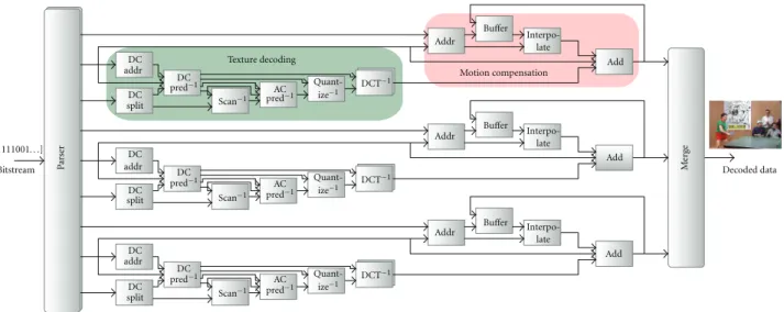
5.1. Concept. MPEG codecs have all a common design. It begins with a parser that extracts motion compensation and texture reconstruction data. The parser is then followed by reconstruction blocs for texture and motion and a merger as presented inFigure 12. This decoder is a full example of coding techniques that encapsulates predictions, scan, quan-tization, IDCT transform, buffering, interpolation, merging and especially the very complex step of parsing.
Table 1gives an idea about the complexity of parsers in MPEG 4 Simple Profile and MPEG Advanced Video Coding (AVC).
Write Write2 Write1 Process Read Read2 Read1 Proc Read3 Init Transition a1 a2 a4 a5 Untagged IN1 Untagged IN2 Untagged IN3 Write done Read done >
Figure8: FSM with created initial state.
S0 S1 S2 a1 a4 a3 a5 a2
Figure9: Initial FSM of an actor.
Table 1: Composition of MPEG-4 simple profile and MPEG-4 advanced video coding RVC-CAL description.
Actors Levels Parser size Decoder size
kSLOC kSLOC
MPEG-4 SP 27 3 9.6 2.9
MPEG-4 AVC 45 6 19.8 3.9
Table2: MPEG4 decoder area consumption. Criterion Transformed design Optimized design Slice flip flops 21,624/135,168 (15%) 13,575/135,168 (10%) Occupied slices 45,574/67,584 (67%) 18,178/67,584 (26%) 4 input LUTs 68,962/135,168 (51%) 34,333/135,168 (25%)
FIFO16/RAMB16s 14/288 (4%) 14/288 (4%)
Bonded IOBs 107/768 (13%) 107/768 (13%)
Actors ofFigure 12are the main functional units some of them are hierarchical composition of actor networks. An actor may be instantiated more than one time so for 27 FU there are 42 actor instantiations.
5.2. Implementation and Results. The achieved automatic transformation was applied on MPEG4 SP intradecoder (see design in Orcc Applications (available at http://orcc .sourceforge.net/)) which contains 29 actors. We omitted the inter decoder part because it is very memory consuming. The HDL generated code was implemented on a virtex4 (xc4vlx160-12ff1148) and the area consumption results we obtained are presented in Table 2. The removal of read
Table3: MPEG4 decoder timing results.
Criterion Transformed design Optimized design Maximum frequency (MHz) 26.4 26.67 Latency (µs) 381.8 306.4 Cadency (MHz) 1.9 2.33
Processing time (ms/image) 13.55 11.01
Throughput frequency (MHz) 1.8 2.2
Global image processing (FPS) 73.8 90.82
actions buffers and process actions had an important impact on the area consumption since it has decreased about 50%.
After the synthesis of the design, we applied a simulation stream of compressed videos.Table 3below presents the tim-ing results of a CIF (352×288) image size video.
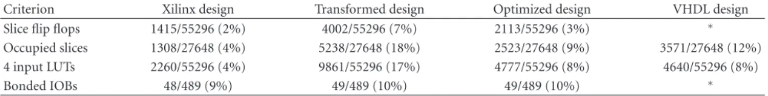
We notice that timing results were partially improved. This is due to the presence of division operations in some actors. In our transformation we replaced divisions by an Euclidean division which is very costly and time consuming. The impact is noticeable since these divisions reduced the maximum frequency by 60%. Therefore, we applied the transformation on the inverse discrete cosine 2D transform (IDCT2D). We chose this actor because it contains very plex algorithm, functions and procedures. We tried to com-pare with an optimal low-level architecture designed by Xilinx experts and also with an existing implementation study of a direct VHDL written algorithm in [25]. For a signi-ficant comparison, we used the same implementation target
Transition Write Store Proc Read1 Write2 Write1 Process Read3 Read2 S1 S0 S2 a1 a5 a2 a4 Untagged IN1 Untagged IN2 Untagged IN3 Write done Read done >
Figure10: Resulting FSM transformation.
actor sum-5 () int ( size=8) IN
= = > int( size=8) OUT:
List ( type: int ( size=8) , size = 8) buffer ;
// closest power of 2 for c ircular buffer List ( type: int ( size=8) , size = 5) data ;
int r e a d I d x : = 0; int w r i t e I d x : = 0; int c o u n t e r : =0 ; action IN:[ i ] = = > // u n t a g g e d a c t i o n guard r e a d I d x - w r i t e I d x < 8
// c o n d i t i o n that the buffer is not full do
buffer [ r eadIdx & 7] : = i ;
// masked read index
r e a d I d x : = r e a d I d x + 1 ;
end
read: action = = > do
data [ c ounter ] : = b u f f e r [ w r i t e I d x & 7] ;
// masked write index
c o u n t e r : = c o u n t e r + 1 ; end r e a d _ d o n e: action = = > guard c o u n t e r = 5 do c o u n t e r : = 0 ; end p r o c e s s: action = = > OUT:[ s ] var int s : = 0 do f o r e a c h int k in 0 .. 4 do s : = s + data [ k ] ; end w r i t e I d x : = w r i t e I d x + 5; // u p d a t e w r i t e I d x end s c h e d u l e fsm state0:
state0 ( read ) - - > state0 ; s t a t e 0 ( r e a d _ d o n e ) - - > state1 ; state1 ( p rocess ) - - > state0 ;
end p r i o r i t y
r e a d _ d o n e > read ;
end end
(a) Transformed equivalent CAL
actor sum-5 () int ( size=8) IN
= = > int( size=8) OUT:
List ( type: int ( size=8) , size = 8) buffer ;
int r e a d I d x : = 0; int w r i t e I d x : = 0; action IN:[ i ] = = > guard r e a d I d x - w r i t e I d x < 8 do
buffer [ readIdx & 7] : = i ; r e a d I d x : = r e a d I d x + 1 ; end p r o c e s s: action = = > OUT:[ s ] guard r e a d I d x - w r i t e I d x > 5 var int s : = 0 do f o r e a c h int k in 0 .. 4 do s : = s + buffer [ k + ( w r i t e I d x &7)] ; end w r i t e I d x : = w r i t e I d x + 5; // u p d a t e w r i t e I d x end end
(b) Optimized equivalent CAL
Texture decoding DC DC DC DC DC DC DC DC DC addr addr addr split split split [01111001. . .] Bitstream Pa rs er pred−1 pred−1 pred−1 pred−1 pred−1 pred−1 Scan−1 Scan−1 Scan−1 AC AC AC Quant-ize−1 Quant-ize−1 Quant-ize−1 DCT−1 DCT−1 DCT−1 Addr Addr Addr Motion compensation Buffer Buffer Buffer Interpo-late Interpo-late Interpo-late Add Add Add M erge Decoded data
Figure12: MPEG 4 SP architecture.
Table4: IDCT2D timing results.
Image size Xilinx design Transformed design Optimized design VHDL design
Maximum frequency (MHz) 37 37 43 41
Latency (µs) 11.52 82.7 28.4 ∗
Cadency (MHz) 30 18.49 21.7 71
Processing time (µs/64 Tokens) 1.99 3.4 2.8 0.89
Throughput frequency (MHz) 26.62 0.72 2.43 62.4
Global image processing (FPS) 1064 31 101 2518
∗Not mentioned in the literature.
of the study which is the Xilinx Spartan 3 XC3S4000. Timing and area consumption results comparison are presented in Tables4and5.
Obviously,Table 5 reveals that area results for the opti-mized design are very close to those of the Xilinx low-level design. This property is noted for all actors containing more computing algorithms then data control and management algorithms. Concerning the area consumption of the VHDL design, it is expectable to find results nearby the optimal design and clearly worse than the Xilinx design and this is due to the synthesis constraints indicated in [25] that favor treatment speed in spite of the surface. This is what explains also the very high FPS rate of the design presented in Table 4. Timing results of the other designs show that the optimized design performances are far from the optimal Xilinx design. This is due to the low level architecture made by Xilinx experts which is completely different and oriented for hardware generation. This architecture is a pipelined set of actors realizing the IDCT2D (rowsort, fairmerge, IDCT1D, separate, transpose, retranspose, and clip) which is a relatively complex design compared with the high-level IDCT2D code used for the transformation.
After comparing with the Xilinx design and a VHDL directly written design, we compared our results with exist-ing generation tools and we considered GAUT hardware gen-erator. This tool is an academic high-level synthesizer from
C to VHDL. It extracts the parallelism and creates a sched-uled dependency graph made of elementary operators. Potentially, GAUT synthesizes a pipe-lined design with mem-ory unit, communication interface and a processing unit. However, like most existing hardware generators, GAUT is not able to manage a system level design with very high com-plexity and a variety of processing algorithms. Moreover, there are so many restrictions on the C input code to have a functioning design. As it was impossible to test the whole MPEG 4 decoder we chose the IDCT2D algorithm to have a comparison with previously presented results.
The IDCT2D is so generated with GAUT and we obtained the results ofTable 6below.
Results show that the optimized transformation gener-ates a better design even for the specific case of study of the IDCT2D.
6. Still Image Codec: LAR Case of Study
The LAR is a still-image coder [26] developed at the IETR/ INSA of Rennes laboratory. It is based on the idea that the spatial coding can be locally dependent on the activity in the image. Thus, the higher the activity the lower the resolu-tion is. This activity is dependent from the variaresolu-tion or the uniformity of the local luminance which can be detected using a morphological gradient. In the following, we detail
Table5: IDCT2D area consumption.
Criterion Xilinx design Transformed design Optimized design VHDL design
Slice flip flops 1415/55296 (2%) 4002/55296 (7%) 2113/55296 (3%) ∗
Occupied slices 1308/27648 (4%) 5238/27648 (18%) 2523/27648 (9%) 3571/27648 (12%)
4 input LUTs 2260/55296 (4%) 9861/55296 (17%) 4777/55296 (8%) 4640/55296 (8%)
Bonded IOBs 48/489 (9%) 49/489 (10%) 49/489 (10%) ∗
∗Not mentioned in the literature.
Table6: IDCT2D area consumption with GAUT.
Criterion GAUT design Optimized design
Slice flip flops 2.080/135.168 (2%) 1.988/135.168 (2%) Occupied slices 2.477/67.584 (3%) 2.353/67.584 (3%) 4 input LUTs 4.243/135.168 (3%) 4.458/135.168 (3%) Bonded IOBs 627/768 (81%) 49/768 (6%) + + Original image FLAT FLAT coder decoder coder decoder Spectral Spectral Transmission Transmission Low resolution image resolution image Middle/high − −
Figure13: LAR concept.
coding principle of the LAR and we present the implement-ation techniques and results using the automatic transforma-tion approach.
6.1. Concept. The LAR coding is based on considering that an image is a superposition of a global information image (mean blocks image), and the local texture image, which is given by the difference between the original image and the global one. This principle is modeled by
I=I+ ⎛ ⎜ ⎝I−I E ⎞ ⎟ ⎠, (5)
where I is the original image, I is the global information image andI−Iis the error image,E. The dynamic range of the error image is consequently dependent on the local activ-ity. In uniform regions,Ivalues are close or equal to I con-sequentlyI−I values are around zero with a low dynamic range.
Considering these principles, the LAR coder concept (Figure 13) is composed of two parts: the FLAT LAR [27]
which is the part insuring the global information coding and the spectral part which is the error spectral coder.
Different profiles have been designed to fit with different types of application. In this paper, we focus on the baseline coder. Its mechanisms are detailed in the following.
The FLAT LAR. The Flat LAR is composed of 3 main parts: the partitioning, the block mean value computation and the DPCM (Differential Pulse Coding Modulation). In our work, only the DPCM is not yet developed with RVC-CAL.
(i) Partitioning: in this part, a Quad-tree partitioning is applied on the image pixels. The principle is to consider the lowest block size (2×2) then to compare the difference between the maximum (MAX) and the minimum (MIN) values of the block with a threshold (THD) defined as a generic variable for the design. If (MAX−MIN)>THD then the actual block size is considered. In the other case, the (N×2)×(N×2) size block is required. this process is recursively applied on the whole image blocks. The output of the overall is the block size image.
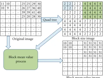
(ii) Block mean values computation process: this process is based on the Quad-tree output image. For each block of the variable size image, a mean value is put in the block as presented in the example ofFigure 14. (iii) The DPCM: the DPCM process is based on the prediction of neighbor values and the quantization of the block mean value image. The observation that a pixel value is mostly equal to a neighbor one led to the following estimation algorithm. If we consider the pixels inFigure 15,Xvalue is estimated with the following algorithm:
If|B−C|<|A−B|thenX=AelseX=C.
The spectral coder, also called the texture coder, is composed of a variable block size Hadamard transform [28] and the Golomb-Rice [29, 30] entropy coder. The Golomb-Rice coder is still in development with the RVC-CAL specifications.
The Hadamard transform derives from a generalized class of the Fourier transform. It consists of a multiplication of a 2m×2mmatrix by an Hadamard matrix (H
m) that has
Quad tree
Original image Block size image
Block mean value image Block mean value
process 2 2 2 2 2 2 2 2 2 2 2 2 2 2 2 2 2 2 2 2 2 2 2 2 2 2 2 2 2 2 2 2 4 4 4 4 4 4 4 4 4 4 4 4 4 4 4 4 4 4 4 4 4 4 4 4 4 4 4 4 4 4 4 4 9 10 10 10 10 10 10 11 25 25 25 20 26 27 28 29 30 36 30 31 31 31 31 31 31 31 31 31 31 31 31 31 31 31 31 39 39 40 40 41 . . . . . . . . . . . . . . . . . . . . . . . . . . . . . . . . . . . . . . . . . . . . . . . . . . . . . . . . . . . . . . . . . . . . . . . . . . . . . . . . . . . . . . . .
Figure14: Block mean value process example.
A
B C
X
Figure15: DPCM prediction of neighbor pixels.
H0is the identity matrix soH0=1. For anym >0,Hmis
then deducted recursively by: Hm= √1 2 Hm−1 Hm−1 Hm−1 −Hm−1 . (6) Here are examples of Hadamard matrices:
H0=1, H1= 1 √ 2 1 1 1 −1 , H2= 1 √ 2 1 1 1 1 1 −1 1 −1 1 1 −1 −1 1 −1 −1 1 , and so forth. (7)
6.2. Implementation and Results. This Section explains the mechanisms of the Hadamard transform and the Quad-tree used in the implementation.
6.2.1. Hardware Implementation. The LAR coding is depen-dent from the content of the image. It applies in the Quad-Tree a morphological gradient to extract information about the local activity on the image. The output is the block size image represented by variable size blocks: 2×2, 4×4 or
Image Memory management memory management memory management memory management memory management
Quad-tree Block size
2×2 blocks H1 H1 H1 H2 H3 Norm.and quant.
H2input H2output H3input H3output
Figure16: LAR baseline developed model.
8×8. Using the block size image, the Hadamard transform applies the adequate transform on the corresponding block. It means that if we have a block size of 2×2 in the size image this block will undergo a 2×2 Hadamard (H1) and
a normalization specific to the 2×2 blocks. This process is identically applied for 4×4 and 8×8 blocks. A quantization step, adapted to current block size, is applied on the Hadamard output image. For each block size, a quantization matrix is predefined. Practically, the normalization during the Hadamard transform is postponed to be achieved with the quantization step so that to decrease the noise due to successive divisions.
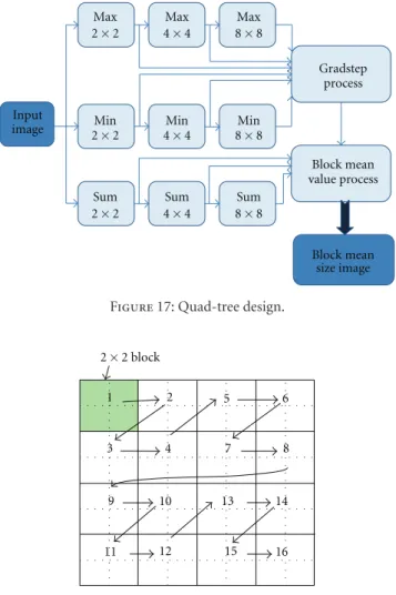
The implemented LAR is presented inFigure 16. As a first step, the memory management block stores the pixels values of the original image line by line. Once an 8×8 block is obtained, the actor divides it into sixteen 2×2 blocks and sends them in a specific order as presented inFigure 18. This order is very important to improve the performance of remaining actors. In fact, considering theFigure 18, when the tokens are so ordered the first 4 tokens correspond to the first 2×2 block, the first 16 tokens to the first 4×4 block, and so forth Consequently, and as presented inFigure 16, the output of theH1is automatically the input of theH2and the
output of theH2is automatically the input of theH3.
In the Quad-tree, this order is also crucial. As presented inFigure 17, the superposition of the same actor (max for example) three times provides in the output of the first actor the maximum values of 2×2 blocks, in the output of the second actor the maximum values of 4×4 block and finally the maximum values of 8×8 blocks in the output of the third one. Using the maximum values and the minimums the morphological gradient in the Gradstep actors can process to extract the block size image. The same tip is used to calculate the block sums with three superposed sum actors. The block mean value actor considers the sums and the sizes to build the block mean value image.
We also notice that an (H2) transform can be achieved
using the (H1) results of the four 2×2 blocks constituting the
4×4 block. The same observation can be made for the (H3)
one. This ascertainment is very important to decrease the complexity of the process. In fact, the Hadamard transform
Max Max Max
2×2 4×4 8×8
2×2 4×4 8×8
2×2 4×4 8×8
Min Min Min
Sum Sum Sum
Input image Gradstep process Block mean value process Block mean size image Figure17: Quad-tree design.
1 2 5 6
3 4 7 8
9 10 13 14
11 12 15 16
2×2 block
Figure18: Memory management unit output order.
of the LAR applies an (H1) transform for the whole image
then it applies the (H2) transform only for the 4×4 and
8×8 blocks and the (H3) transform only for the 8×8 blocks.
The (H2) and the (H3) transforms are different from the full
transforms as they are much less complex. Consequently, as shown inFigure 16, we designed theH2and theH3usingH1
actors associated with memory management units. They sort tokens in the adequate order and, considering the block size, whether the block is going to undergo the transform or not.
It is very important to mention that almost actors have been developed with generic variables for memory sizes or gradsteps which means that the design are flexible for easy transformation from an image size to another or for adding higher Hadamard process (H4,H5, etc.).
In [15], we added some optimizations on the processes using a Ping-Pong memory management algorithm [31] to pipeline the process.
6.2.2. Results and Comparison. As mentioned above, this work aims at comparing hardware implementation perfor-mances of the same LAR architecture generated with the optimized automatic transformation and with a manual transformation. The achieved automatic transformation was applied on the 23 actors of the LAR using Orcc. The HDL
Table7: LAR coder area consumption.
Transformation Automatic Manual
Slice flip flops 20.452/135.168 (15%) 12.157/135.168 (8%) Occupied slices 47.576/67.584 (70%) 43.602/67.584 (67%) 4 input LUTs 59.868/135.168 (44%) 53.417/135.168 (39%)
Bonded IOBs 41/768 (5%) 41/768 (5%)
Table8: LAR timing results.
Transformation Automatic Manual
Development time 30% 100%
Maximum frequency (MHz) 61.43 85.27
Latency (ms) 0.42 0.12
Throughput frequency (MHz) 3.5 5.6
Processing time (ms/image) 35 19
Global image processing (FPS) 34 53
generated code was implemented on a virtex4 (xc4vlx160-12ff1148). The area consumption results obtained are pre-sented with those of manual transformations inTable 7.
After the synthesis of the design, we applied a simulation stream of compressed videos. Table 8 below presents the timing results of a CIF (352×288) image size video.
For area consumption, the difference is not considerable for LUTs and occupied slices and it can be explained by the fact that the transformation applies a general modification whatever the complexity of the actor. Also, the fact of creating an internal buffer for every input port involves more area consumption.
Concerning the timing results, the automatic and the manual transformed designs performances remain close and acceptable. The latency difference is explained by the fact that the untagged actions, as always given priority over the rest of actions, promote the data reading. It means that, as long as there is data in the FIFO, the untagged action fires even if there are enough data to fire the processing actions. This problem will also be resolved by further optimizations of the buffer size.
7. Conclusion
This paper presented an automatic transformation of RVC-CAL from high- to low-level description. The purpose of this work is to find a general solution to automate the whole hardware generation flow from system level. This transfor-mation allows avoiding structures that are not understand-able by RVC-CAL hardware compilers. We applied this auto-matic transformation on the 29 actors of MPEG4 part2 video intradecoder and successfully obtained the same behavior of the multitoken design and a synthesizable hard-ware implementation. To change the test context, we auto-matically transformed a high-level design of the LAR still image codec and obtained relatively acceptable results.
Several optimization processes were added to the trans-formation to reduce the area consumption about 50%. The transformation process is currently generalized for all actors.
The most important in this work is that we contributed in making RVC-CAL hardware generation very rapid with an average gain of 75% of conception, development, and valida-tion time compared with manual approach. We insured that the generation is applicable at system level whatever the com-plexity of the actor.
Currently, improvements are also in progress to custo-mize the transformation depending on the actor complexity analysis. A future work will be the study of the impact of the transformation on the power consumption of the generated implementation.
Acknowledgments
Special thanks to Matthieu Wipliez, Damien De Saint-Jorre, and Herv´e Yviquel for their relevant contributions in the source code.
References
[1] B. Bailey, G. Martin, and A. Piziali,ESL Design and Verification: A Prescription for Electronic System-Level Methodology, The Morgan Kaufmann Series in Systems on Silicon, Morgan Kaufmann, 2007.
[2] “Synopsys: Synphony C compiler,” In ESL design and veri-fication: a prescription for electronic system-level methodo-logy, http://www.synopsys.com/systems/blockDesign/HLS/ pages/SynphonyC-Compiler.aspx
[3] “Mentor Graphics: Designing High-Performance DSP Hard-ware Using Catapult C Synthesis and the Altera Accele-rated Libraries,” In ESL design and verification: a prescrip-tion for electronic system-level methodology, http://www .altera.com/literature/wp/wp-01039.pdf.
[4] “Mentor Graphics: Catapult C,” In ESL design and verifica-tion: a prescription for electronic system-level methodology, 2010,http://www.mentor.com/esl/catapult/overview. [5] F. Plavec, Z. Vranesic, and S. Brown, “Towards compilation of
streaming programs into FPGA hardware,” inProceedings of the Forum on Specification, Verification and Design Languages (FDL ’08), pp. 67–72, September 2008.
[6] D. Lau, O. Pritchard, and P. Molson, “Automated generation of hardware accelerators with direct memory access from ANSI/ISO standard C functions,” inProceedings of the 14th Annual IEEE Symposium on Field-Programmable Custom Com-puting Machines (FCCM ’06), pp. 45–56, April 2006.
[7] T. M. Bhatt and D. McCain, “Matlab as a development environment for FPGA design,” in Proceedings of the 42nd annual Design Automation Conference (DAC ’05), ACM, New York, NY, USA, 2005.
[8] P. Coussy, D. D. Gajski, M. Meredith, and A. Takach, “An introduction to high-level synthesis,”IEEE Design and Test of Computers, vol. 26, no. 4, pp. 8–17, 2009.
[9] P. Coussy, C. Chavet, P. Bomel, D. Heller, E. Senn, and E. Mar-tin, “GAUT: a high-level synthesis tool for DSP applications,” inHigh-Level Synthesis: From Algorithm to Digital Circuits, P. C. A. Morawiec, Ed., Springer, 2008.
[10] J. Eker and J. Janneck, “CAL language report,” ERL Technical Memo UCB/ERL M03/48, University of California at Berkeley, 2003.
[11] C. Brooks, E. Lee, X. Liu, S. Neuendorer, and Y. Zhao, Eds., “HZ: PtolemyII—heterogeneous concurrent modeling and design in Java (Volume 1: introduction to ptolemyII),”
Technical Memorandum UCB/ERL M04/27, University of California, Berkeley, Calif, USA, 2004.
[12] E. A. Lee and T. M. Parks, “Dataow process networks,” Pro-ceedings of the IEEE, vol. 83, no. 5, Article ID 773801, 1995. [13] G. Kahn, inProceedings of the IFIP Congress The Semantics of
a Simple Language for Parallel Programming. In Information Processing, J. L. Rosenfeld, Ed., pp. 471–475, North-Holland, New York, NY, USA, 1974.
[14] M. Mattavelli, I. Amer, and M. Raulet, “The reconfigurable video coding standard,”IEEE Signal Processing Magazine, vol. 27, no. 3, pp. 159–167, 2010.
[15] K. Jerbi, M. Wipliez, M. Raulet, M. Babel, O. Deforges, and M. Abid, “Automatic method for efficient hardware implement-ation from rvc-cal dataflow: a lar coder baseline case study,” Journal Of Convergence, vol. 1, Article ID 8592, 2010. [16] K. Jerbi, M. Raulet, O. Deforges, and M. Abid, “Automatic
gen-eration of synthesizable hardware implementation from high level RVC-CAL design,” inProceedings of the 37th International Conference on Acoustics Speech and Signal Processing (ICASSP ’12), pp. 1597–1600, 2012.
[17] J. Janneck, I. Miller, D. Parlour, G. Roquier, M. Wipliez, and M. Raulet, “Synthesizing hardware from dataflow programs: an mpeg-4 simple profile decoder case study,”Journal of Signal Processing Systems, vol. 63, no. 2, pp. 241–249, 2009.
[18] M. Mattavelli, J. W. Janneck, and M. Raulet, “MPEG reconfig-urable video coding,” inHandbook of Signal Processing Systems, S. S. Bhattacharyya, E. F. Deprettere, R. Leupers, and J. Takala, Eds., pp. 43–67, Springer, 2010.
[19] J. W. Janneck, M. Mattavelli, M. Raulet, and M. Wipliez, “Reconfigurable video coding: a stream programming approach to the specification of new video coding standards,” inProceedings of the ACM SIGMM Conference on Multimedia Systems (MMSys ’10), pp. 223–234, New York, NY, USA, February 2010.
[20] S. Bhattacharyya, G. Brebner, J. Eker et al., “OpenDF—a dataflow toolset for reconfigurable hardware and multicore systems,” in1st Swedish Workshop on MultiCore Computing (MCC ’08), Ronneby, Sweden, November 2008.
[21] R. Gu, J. W. Janneck, S. S. Bhattacharyya, M. Raulet, M. Wipliez, and W. Plishker, “Exploring the concurrency of an MPEG RVC decoder based on dataflow program analysis,” IEEE Transactions on Circuits and Systems for Video Technology, vol. 19, no. 11, pp. 1646–1657, 2009.
[22] G. Roquier, M. Wipliez, M. Raulet, J. W. Janneck, I. D. Miller, and D. B. Parlour, “Automatic software synthesis of dataflow program: an MPEG-4 simplpe profile decoder case study,” inProceedings of IEEE Workshop on Signal Processing Systems (SiPS ’08), pp. 281–286, Washington, DC, USA, October 2008. [23] M. Wipliez, G. Roquier, and J. F. Nezan, “Software code gen-eration for the RVC-CAL language,”Journal of Signal Process-ing Systems, vol. 63, no. 2, pp. 203–213, 2011.
[24] J. Eker and J. W. Janneck, “A structured description of dataflow actors and its application,” Technical Memorandum UCB/ERL M03/13, Electronics Research Laboratory, University of Cali-fornia at Berkeley, 2003.
[25] R. K. Megalingam, K. B. Venkat, S. V. Vineeth, M. Mithun, and R. Srikumar, “Hardware implementation of low power, high speed DCT/IDCT based digital image watermarking,” in Proceedings of the International Conference on Computer Technology and Development (ICCTD ’09), pp. 535–539, November 2009.
[26] O. D´eforges, M. Babel, L. B´edat, and J. Ronsin, “Color LAR codec: a color image representation and compression scheme based on local resolution adjustment and self-extracting
region representation,”IEEE Transactions on Circuits and Sys-tems for Video Technology, vol. 17, no. 8, pp. 974–987, 2007. [27] O. Deforges and M. Babel, “LAR method: from algorithm to
synthesis for an embedded low complexity image coder,” in Inproceedings of the 3rd International Design and Test Workshop (IDT ’08), pp. 187–192, December 2008.
[28] J. Poncin, “Utilisation de la transformation de Hadamard pour le codage et la compression de signaux d’images,”Annales des T´el´ecommunications, vol. 26, no. 7-8, pp. 235–252, 1971. [29] R. F. Rice, “Some practical universal noiseless coding
tech-niques,” Technical Report 79–22, 1979.
[30] S. W. Golomb, “Run length codings,”IEEE Transactions on Information Theory, vol. 12, no. 7, Article ID 399401, 1966. [31] C. H. Chang, M. H. Chang, and W. Hwang, “A flexible
two-layer external memory management for H.264/AVC decoder,” in Inproceedings of the 20th Anniversary IEEE International SOC Conference, pp. 219–222, September 2007.