(Bulletin of Electrical Engineering and Informatics) Vol.1, No.2, June 2012, pp. 165~178
ISSN: 2089-3191 165
Performance Evaluation of Direct Torque Control with
Permanent Magnet Synchronous Motor
Jaswant Singh1, B. Singh2, S P Singh3 1
Asst. Prof. & Head, Dept of Electrical Engineering P.K. Institute Technology, Mathura -281206 (U.P.), India
2
Asst. Prof., KNIT Sultanpur-228118(U.P.), India 3
Assistant Professor in Department of Electrical Engineering of Kamla Nehru Institute of Technology, Sultanpur (U.P.)-228118, India
e-mail: [email protected], [email protected], [email protected]
Abstrac
t
The direct torque control theory has achieved great success in the control of permanent magnet synchronous motor. A Direct Torque Control (DTC) scheme of Permanent Magnet Synchronous Motor (PMSM) is presented. Based on in-depth analysis of PMSM mathematical model in abc frame and
αβ
frame are established and the operation principle of DTC-SVPWM system, the relationships between the torque and fundamental components. A novel space vector pulse width modulation (SVPWM) method which has a feature of low harmonic is proposed. The proposed method is adopted to implement the direct torque control (DTC) of a three-phase PMSM. A large number of simulation results show that the DTC System of PMSM has fast response and good dynamic performance. To aim at the direct torque control in PMSM Drives, this paper explained the theoretical basis of the direct torque control (DTC) for PMSM firstly, and then explained the difference between the applications of DTC-SVPWM and PMSM. Finally, the MATLAB/Simulink models were developed to examine the DTC- SVPWM for PMSM. The simulation results are presented in this paper.
Keywords: Direct torque control (DTC), permanent magnet synchronous motor (PMSM), space vector
pulse with modulation (SVPWM), modeling equations, current estimation, Stator flux linkage
NOMENCLATURE Te Torque Ld d-axis inductances Lq q-axis inductances s
ψ
Stator fluxΨf Permanent magnet flux p Number of pole pairs
δ Torque angle (the angle between
δ
sandδ
f )s
δ
∆
The change in torque angle due to move ofδ
sf
δ
∆
The change in torque angle due to move ofδ
f,
d q
Rotor direct and quadrature axis indexesf
ψ
Rotor flux (PM).,
d
L Lq
d axis and q axes synchronous inductances.,
d q
i i
d axis and q axes currents.,
d q
V V
d axis and q axis voltages. ,q d
ψ ψ
d and q axes flux linkages.J
Moment of inertia.J
B
Friction coefficient.B
T
Friction torque.1. Introduction
Permanent magnet synchronous motors (PMSM) are widely used in high-performance drives such as industrial robots and machine tools for their advantages on high power density, high-torque, free maintenance and so on. In recent years, the magnetic and thermal capabilities of the PM have been considerably increased by employing the high-coercive PM materials [1]. In last few years, permanent magnet synchronous motor (PMSM) consequently is acquired in more and more far-ranging application, because of its properties such as small volume, light weight, high efficiency, small inertia, rotor without heat problem, etc. [2].
Space vector pulse width modulation DTC is a technique to reduce the ripples of the electromagnetic torque and flux linkage. Space vector modulation techniques have several advantages which offer better DC bus utilization, lower torque ripples, lower total harmonic distortion in the AC motor current, lower switching loss, and easier to implement in the digital systems.
Direct Torque Control (DTC) is a new control method after vector control. It abandons decoupling thought of vector control, and uses the stator flux linkage directly to control the flux linkage and the torque of motor. Thus, the dynamic response of the system is very fast [3]. The DTC control strategy is applied for PMSM in order to improve the torque characteristics of the motor, which currently has caused the extensive attention of people. The traditional DTC usually adopts bang-bang control strategy to implement. But this control strategy cannot meet the system requirements both of torque and flux linkage at the same time, which leads to large fluctuations of flux linkage and torque generated by system and leads to the problem of pulse current and switches noise caused by higher switching frequency changes. Space Vector Pulse Width Modulation (SVPWM) control strategy has been widely used in the field of motor speed control, due to its potential advantages, such as small current waveform distortion, high utilization of DC voltage, easy-to-digital implementation, constant switching frequency of inverter, effectively to reduce pulsation of the motor torque and flux linkage, etc. The object studied in this paper is the permanent magnet synchronous. In application, the DTC strategy, which based on the SVPWM, is adopted to simulate. The result shows that the system has the advantage of fast response, good dynamic performance and so on [4] [5]. The simulation results shows the proposed DTC-SVPWM system having less flux linkage and torque ripples while it maintains as good torque response as the DTC-SVPWM. At the same time the complexity of the power circuit does not increase.
2. Mathematical Model of PMSM
PMSM is an important category of the electric machines, in which the rotor magnetization is created by permanent magnets attached to the rotor. Many mathematical models have been proposed for different applications, such as the abc-model and the two axis dq-model. Due to the simplicity of the two axis dq-model, it becomes the most widely used model in PMSM engineering controller design. The dq-model offers significant convenience for control system design by transforming stationary symmetrical AC variables to DC ones in a rotating reference frame. Based on the dq reference frame theory, the mathematical model of the PMSM can be expressed as the following equations: The two axes PMSM stator windings can be considered to have equal turn per phase. The rotor flux can be assumed to be concentrated along the d axis while there is zero flux along the q axis, an assumption similarly made in the derivation of indirect vector controlled induction motor drives. Also, rotor flux is assumed to be constant at a given operating point. There is no need to include the rotor voltage equation as in the induction motor since there is no external source connected to the rotor magnet and variation in the rotor flux with respect to time is negligible. The stator equations of the induction machine in the rotor reference frames using flux linkages are taken to derive the model of the PMSM. The rotor reference frame is chosen because the position of the rotor magnets determine independently of the stator voltages and currents, the instantaneous induced emfs and subsequently the stator currents and torque of the machine. In Induction
motor, the rotor fluxes are not independent variables, they are influenced by the stator voltage and currents and that is why any frame of reference is suitable for the dynamic modeling of the induction machine.
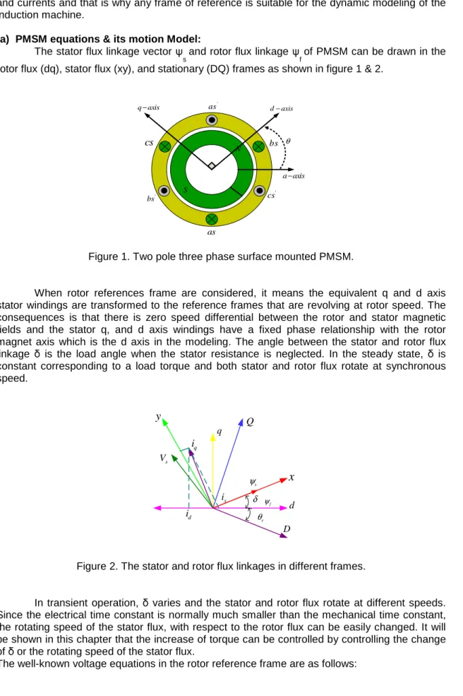
(a) PMSM equations & its motion Model: The stator flux linkage vector ψ
s and rotor flux linkage ψf of PMSM can be drawn in the rotor flux (dq), stator flux (xy), and stationary (DQ) frames as shown in figure 1 & 2.
N S q axis− d−axis a axis− ' cs as cs bs ' bs ' as θ
Figure 1. Two pole three phase surface mounted PMSM.
When rotor references frame are considered, it means the equivalent q and d axis stator windings are transformed to the reference frames that are revolving at rotor speed. The consequences is that there is zero speed differential between the rotor and stator magnetic fields and the stator q, and d axis windings have a fixed phase relationship with the rotor magnet axis which is the d axis in the modeling. The angle between the stator and rotor flux linkage δ is the load angle when the stator resistance is neglected. In the steady state, δ is constant corresponding to a load torque and both stator and rotor flux rotate at synchronous speed. D Q d q q i d i s V
y
x
x i δ s ψ f ψ r θFigure 2. The stator and rotor flux linkages in different frames.
In transient operation, δ varies and the stator and rotor flux rotate at different speeds. Since the electrical time constant is normally much smaller than the mechanical time constant, the rotating speed of the stator flux, with respect to the rotor flux can be easily changed. It will be shown in this chapter that the increase of torque can be controlled by controlling the change of δ or the rotating speed of the stator flux.
d d d d r q d v R i d t ψ ω ψ = + − (1) q q q q r d d v R i d t ψ ω ψ = + + (2)
where Rd and Rq are the Quadrature and direct-axis winding resistances which are equal and be referred to as Rs is the stator resistance. To compute the stator flux linkage in the q and d axes, the current in the stator and rotor are required. The permanent magnet excitation can be modeled as a constant current source,
i
f the rotor flux along d axis, so the d axis rotor current isi
f.
The q axis current in the rotor is zero, because there is no flux along this axis in the rotor, by assumption. Then the flux linkages are written as in equation (3).
d
L i
d dL i
m fψ
=
+
(3)q
L i
q qψ
=
(4) where Lm is the mutual inductance between the stator winding and rotor magnets. Substituting these flux linkages into the stator voltage equations gives the stator equations (5): [6] [7].
(
)
q s q r d d f q qv
=
R i
+
ω
L i
+
ψ
+
ρ
L i
(5)(
)
d s d r q q d d f d d dv
=
R i
+
ω
L i
+
ρ
L i
+
ψ
R
+
L i
(6) Arranging the equations above in matrix form:q q r d r m f q q r q d d f d d R L L L i v i L R L v i ρ ω ω ω ρ ρψ + = + − + (7)
The developed torque motor is being given by (8) 3
( )
2
e d d q d
T = P ψ i −ψ i (8)
which upon substitution of the flux linkages in terms of the inductances and current yields 3 ( ( ) ) 2 e d d d q q d T = P ψ i + L − L i i (9) f
ψ
is the flux through the stator windings due to the permanent magnet.ψ
f=
L i
m f (10)The mechanical Torque equation is (11)
m e L m d T T B J d t ω ω = + + (11) Solving for the rotor mechanical speed from the equation above is (12).
( e L ) m T T B dt J ω ω =
∫
+ + (12) And 2 m r P ω ω= (13)In the equation above ω
r is the rotor electrical speed where as ωm is the rotor mechanical speed. (b) Parks Transformation:
The dynamic d-q modeling is used for the study of motor during transient and steady state. It is done by converting the three phase voltages and currents to dqo variables by using Parks transformation. Converting the phase voltages variables
V
abctoV
qdovariables in rotor reference frame, the following equations (14) & (15) are obtained [8]:0
cos cos( 120) cos( 120)
2
sin sin( 120) sin( 120)
3 1 1 1 2 2 2 q r r r a d r r r b c V V V V V V θ θ θ θ θ θ − + = − + (14) 0 cos sin 2 cos( 120) sin( 120) 3 cos( 120) sin( 120) q a r r b r r d r r c V V V V V V θ θ θ θ θ θ = − − + + (15) (c) Equivalent Circuit of PMSM:
From the d-q modeling of the motor using the stator voltage equations, the equivalent circuit of the motor can be derived as shown in figure 3. Assuming rotor d axis flux from the permanent magnet is represented by a constant current source as described in the following equation
ψ
f=
L i
m f figure below is obtained [9].s R r q ω ψ Lls= −Ld Lm d V m L If d
i
s Rωψ
r d Lls= −Lq Lm qV
L
m qi
(a) d-axis. (b) q-axis.
Figure 3. Equivalent Circuit of PMSM.
(d) The Torque Equation In x-y Reference Frame:
With the transformation below, equation (6) can be transformed to stator flux reference frame [10]. cos sin sin cos x d y q F F F F
δ
δ
δ
δ
= − (16)The inverse transformation is
c o s s in s i n c o s d x q y F F F F δ δ δ δ − = (17)
sin co s q s d s ψ δ ψ ψ δ ψ = = (18)
where
ψ
s represents the amplitude of the stator flux linkage. Substituting (16) and (17) for current into (8) gives:3 ( sin cos ) (cos sin )
2 d x y q y P T =
ψ
iδ
+iδ
−ψ
δ
+iδ
2 2 3 2 x d q y d x d q y d s s s s i i i i Pψ ψ
ψ
ψ ψ
ψ
ψ
ψ
ψ
ψ
= + − + (19)Equation (19) means that the torque is directly proportional to the y –axis component of the stator current if the amplitude of the stator flux linkage is constant.
(e) The Flux Linkage Equations In The xy Reference Frame : Equation (3) can be rewritten into matrix form as follows:
0
0
0
d d d f q q qL
i
L
i
ψ
ψ
ψ
=
+
(20)Substituting (3) into (7) gives: 0
cos sin cos sin
0
sin cos sin cos 0
x d f y q L L ψ ψ δ δ δ δ ψ δ δ δ δ − − = + (21)
(f) PMSM’s With Pole Saliency:
For a PMSM’s with pole saliency,
L
d≠
L
qthe torque equation in terms of stator flux linkage and angleδ
can be obtained by solving ix with
ψ
y=
0
2 sin [( ) ( ) cos 2 ] ( ) sin 2 f d q d q y x d q L L L L i i L L ψ δ δ δ − + + − = + (22) Then the torque equation is as follows:3 [2 sin ( )sin 2 ] 4 q d s f q s q d P T L L L L L ψ ψ δ ψ δ = − − (23)
Equation (23) consists of two terms; the first is the excitation torque, which is produced by the permanent magnet flux. The second term is the reluctance torque. For PMSM with pole saliency, the amplitude of the stator flux should be changed with the change of actual torque even for constant torque operation. Under the condition of constant amplitude of
ψ
sby differentiating (23) with respect to time, the increasing rate of torque at t = 0 can be obtained in (24) [11]. 3 [2 sin 2 ( ) cos 2 ] 4 q d s f q s q d dT P d L L L dt L L dt δ ψ ψ δ ψ δ = − − (24)From (23) and (24) can be seen that electromagnetic torque in PMSM is determined by the
δ
angle; quick dynamic response can be achieved by changingδ
as quickly as possible.And according to (25), fast dynamic response can be achieved if the amplitude of the stator flux linkage is chosen as (25). ( ) s q f q d L L L ψ < ψ − (25)
3. Speed and Torque Control Using Space Vector Pulse Width Modulation (DTC-SVPWM)
The block scheme of the investigated speed and torque control with space vector pulse width modulation (DTC-SVPWM) for a voltage source SVPWM inverter fed PMSM is presented in Figure 4. The internal structure of the estimation torque and flux controller is shown.
* r ω r ω r ω ∆ ∆Te e T * e T dδ * sr ψ r ω sd ψ sq ψ isq sd i r θ r θ s iα isβ s vα vsβ sd v sq v a i c i b i DC link capacitor 144424443 220V AC Source a i ib
Figure 4. Structure block diagram of PMSM proposed with DTC-SVPWM scheme .
a). Mathematical Model
Direct Torque Control calculates and controls stator flux linkage and torque of PMSM directly to achieve high dynamic performance in the stator coordinate system. A block diagram of DTC with PMSM is shown in Figure 4. isd and isq' is the components of i, in the d-q axis, which
can be obtained from the phase current sampling values ia and ih ' through Clark coordinate
transformation and Park coordinate transformation. Then
ψ
sd,ψ
sq andT
e could be estimated by isd and isq. This system uses three-way closed-loop control of speed, flux linkage and torque.Adopt speed deviation
∆
ω
r as input value, outer loop PI controller outputsT
e*, which is the given value of torque loop. Then take torque deviation∆
T
e as input value, torque loop PIcontroller outputs
d
δ
the correction value ofδ
, which is the angle betweenψ
PM andψ
S,v
sdand
v
sq the components of u, in the d-q axis can be estimated byd
δ
,ψ
sd andψ
sq. SVPWMcontrol signals can be generated through inverse Park transformation with
v
sd andv
sq, and then drive permanent magnet synchronous motor [10] [11]. In the figure 2, flux linkage estimator can be expressed as:2 2 sd sd PM sq sq sq sr sd sq
L i
L i
ψ
ψ
ψ
ψ
ψ
ψ
=
+
=
=
+
(26) Wherearctan
sq sdψ
δ
ψ
=
Torque estimator can be expressed as:
3
(
)
2
e sd sq sq sd
T
=
p
ψ
i
−
ψ
i
(27) Voltage estimator can be expressed as:sq sq s sq r sd sd sd s sd r sq
d
v
R i
dt
d
v
R i
dt
ψ
ω ψ
ψ
ω ψ
=
+
+
=
+
−
(28)Where, dt is flux linkage sampling time,
ψ
sr* is the given value of torque stator flux linkage. In addition, * *cos (
)
cos
sin (
)
sin
sd sr sr sq sr srd
d
d
d
ψ
ψ
δ
δ ψ
δ
ψ
ψ
δ
δ ψ
δ
=
+
−
=
+
−
(29)To reduce the computation,
d
ψ
sdandd
ψ
sq can be expressed as:* *
(
cos
sin
)
(
cos
sin
)
sq sd sd sr sd sr sr sq sd sq sr sq sr srd
d
d
d
d
d
ψ
ψ
ψ
ψ
δ
δ ψ
ψ
ψ
ψ
ψ
ψ
ψ
δ
δ ψ
ψ
ψ
=
−
−
=
+
−
(30)b). Proposed PMSM with DTC-SVPWM Scheme
The block diagram of the proposed PMSM DTC-SVPWM drive is shown in Figure 4. The speed controller is a classical proportional-integral (PI) regulator, which produces the reference torque [11]. The calculated torque is compared with the reference torque. Then x-axis voltage component and y-axis voltage component of the stator voltage in the stator flux reference frame are calculated in the voltage controller. After xy/αβ transformation, the α -axis voltage component and β -axis voltage component of the stator voltage are obtained and input into SVPWM. Then the inverter is controlled by the space vector pulse width modulation (SVPWM). A DC bus voltage and two phases current are detected to calculate the stator flux linkage and torque. The speed is also estimated in the toque, flux, angle and speed estimator.
4. Simulation Result in MATLAB/Simulink
A block diagram of the proposed PMSM drive based on SVPWM is shown in Figure 5. The parameters of PMSM and control parameter are shown in Table 1 and 2. And the
availability is confirmed by computer simulations. The results under the PI speed controller and the proposed scheme are shown in Figure 4, respectively.
Table 1 Specification of DTC-SVPWM
Motor constants Values
pT
K
100 iTK
0.089 pK
ψ 4.5 iK
ψ 0.90 Reference speedω
m 880 rpmTable 2 Specification of the PMSM
S.No. Motor constants Values
1 Stator resistance Rs 4.765
Ω
2 Torque
T
e 1.7 Nm3 d-axis inductance ( Ld) 0.014H
4 q-axis inductance (Lq) 0.014H
5 Permanent magnet flux
ψ
f 0.18486 rated Speed
ω
m 3750 rpm7 rated current
i
rated 6.89 amp8 Number of poles P 2
9 Moment of inertia 0.0001051
10 Friction factor 4.047e-005
11 Stator flux reference
ψ
s 0.1848 Wb12 DC bus voltage 300.9 V
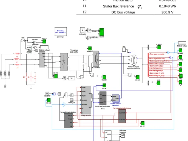
Figure 5. Simulink model of PMSM with DTC-SVPWM scheme.
Under the mentioned simulation conditions above, it shows that the dynamic response performances of the PMSM drive based on the proposed scheme has been improved to some extent compared with the system based on the conventional PI speed controller. A simulation model of the system was established by Simulink in MATLAB. A comparative simulation study on DTC based on SVPWM was carried out. Figure 8 shows the waveforms of dc-link voltage
and current source fed svpwm PMSM drive. Here, dc-link voltage is boosted to 309V due to voltage -source. The dc link voltage is roughly equal to 1.38 times the line voltage (220 V). This shows that the voltage-source inverter can only produce an ac voltage which is not limited by the dc link voltage; it reaches to steady state value. Steady state value of three phase stator current is 6.9 A. The simulated stator current waveforms confirm that the steady state performance of permanent magnet synchronous motor is greatly improved with DTC-SVPWM. The result for the three phase stator current estimation are shown in figure 8, inverter switching frequency is 20 KHz. The given speed is 880 rad/min, and the comparative results of the Rotor actual speed of the PMSM wave form (rpm) are shown in Figure 10, and reference speed of the PMSM are shown in figure 11. Figure 12 is the Electromagnetic Torque (Te_-3Nm to +3Nm) of the PMSM actual torque and reference torque as shown in figure 12 & 13.Fig. 14 & 15 Shows the Stator Flux_
ψ
d = 13.87 waveform of the PMSM curve and Stator Flux_ψ
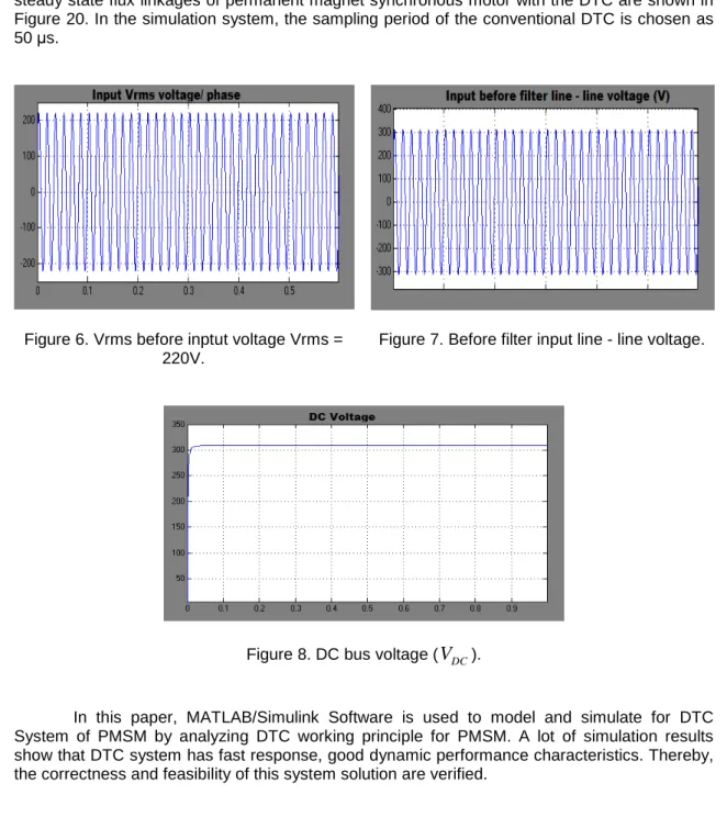
q = 0.076 waveform of the PMSM curve, figure 12 shows the comparison of torque. Figure 13 shows comparison of dynamic torque response on step mutation of given torque from -3Nm to +3Nm. It can be seen that the torque ripple of PMSM is reduced greatly in the latter strategy. The steady state flux linkages of permanent magnet synchronous motor with the DTC are shown in Figure 20. In the simulation system, the sampling period of the conventional DTC is chosen as 50 µs.Figure 6. Vrms before inptut voltage Vrms = 220V.
Figure 7. Before filter input line - line voltage.
Figure 8. DC bus voltage (
V
DC).In this paper, MATLAB/Simulink Software is used to model and simulate for DTC System of PMSM by analyzing DTC working principle for PMSM. A lot of simulation results show that DTC system has fast response, good dynamic performance characteristics. Thereby, the correctness and feasibility of this system solution are verified.
a). Three phase stator current
The PMSM motor drive generated three phase stator current in shown in figure 9.
Figure 9. Three phase stator current_Iabc of the PMSM.
b). Speed estimation
The speed estimator is based on the relation of stator flux angle and rotor flux angle. The given speed is 880 rad/min, and the comparative results of the Rotor actual speed and reference speed of the PMSM wave form (rpm) are shown in Figure 10 & 11. The real and estimated speed in the proposed DTC-SVPWM scheme when the reference speed has 880 rad/s at startup at t=0.1s.
Figure 10. Rotor actual speed of the PMSM wave form (rpm).
Figure 11. Reference speed of the PMSM.
Figure 10 shows that the estimated speed could accurately track the change of the real speed when speed reference has changed and has fast response. The proposed DTC-SVPWM system is relatively robust with respect to the change of the speed reference.
c). Torque and flux estimation:
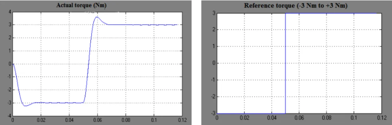
Figure 10-15 show torque and flux response of the proposed DTC-SVPWM for PMSM when the load torque has step change from negative three to positive three Nm (-3 Nm to +3Nm) at 0.03s. The proposed control system and the proposed DTC-SVPWM system have good dynamic performance. The step response actual Electromagnetic Torque (Te_-3Nm to +3Nm) of the PMSM and reference torque as shown in figure 12 & 13.
Figure 12 shows the comparison dynamic torque response on step mutation of given torque from -3Nm to +3Nm. The flux estimation of the permanent magnet synchronous motor (PMSM) drive is two axis, d-axis and q-axis. The Stator actual flux d-direction (
ψ
actual d_ ) andactual flux q-direction (
ψ
actual q_ ) of the flux as shown in Figure 14 & 15 which shows the Stator Flux_ψ
d = 13.87 Wb waveform of the PMSM curve and Stator Flux_ψ
q = 0.076 Wb waveform of the PMSM curve. They are used in reference fluxψ
ref = 0.1848 Wb.Figure 12. Electromagnetic Torque (Te_Nm) of the PMSM.
Figure 13. The step response reference torque is (Tref -3Nm to +3Nm).
Figure 14. Stator Flux_
ψ
d = 13.87 of the PMSM.Figure 15. Stator Flux_
ψ
q = 0.076 of the PMSM.d). Stator voltage_dq of the PMSM:
The stator voltage d-direction and q-direction (
v and v
sq sd) of the permanent magnet synchronous motor (PMSM) as shown below:f). Hall Effect condition of the PMSM:
The permanent magnet synchronous motor drive is proposed technique Direct torque control–space vector pulse width modulation (DTC-SVPWM), the hall effect conditions are
,
a b c
h h and h
, the results are equal to the stator current performanceFigure 18. Three Hall Effect of the PMSM.
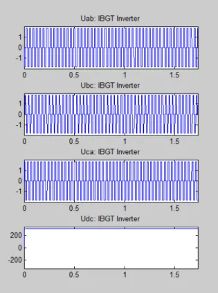
Figure 19. Inverter voltage of
,
,
ab bc ca dc
V
V V and V
.Figure 20. Flux trajectory of the PMSM with DTC.
5. Conclusion
In this paper, direct torque control with Permanent magnet synchronous motor (PMSM) are proposed and simulated in SIMULINK/MATLAB.This paper presents a new DTC adjustable
speed and flux control system based on the V-source inverter topology which has been presented. The performance of three phase Permanent magnet synchronous motor (PMSM) is analyzed by using this technique; Simulation results are analyzed by the output waveforms in term of Permanent magnet synchronous motor (PMSM) outputs (performance parameters). A simulation model of the system was established by Simulink in MATLAB. A comparative simulation study on DTC based on SVPWM was carried out.
A Direct torque control –space vector pulse width modulation (DTC-SVPWM) technique is used for generating a desired value of pulses by using an appropriate value of switching frequencies. Performance of 3-phase PMSM is investigated for the different load conditions and their comparison is also presented in this paper. The results of simulation have shown that the PMSM drive with the proposed control scheme has the merits of simple structure, robustness, quick tracking performance. SVPWM allows the operation of inverter in over modulation region. This proposed strategy considers the inverter as a single unit and greatly reduces the complexity and cost when compared with traditional systems. It has reduced harmonics, low switching stress power and low common mode noise. The results are shown to verify these new features. A lot of simulation results show that DTC system has fast response, good dynamic performance characteristics. Thereby, the correctness and feasibility of this system solution are verified.
References
[1] I Takahashi, T Naguchi. A new quick-response and high-efficiency control strategy of an induction motor. IEEE Trans. Ind. Appl. 1986; IA(22): 820-827.
[2] Li Ye, Yan Xinpin. The perspective and status of PMSM electricalserro system. Micromotors Servo Technique. 2001; 4: 30-33.
[3] Lixin Tang, Limin Zhong. A novel direct torque control for interior permanent magnet synchronous machine drive with low ripple in toque and flux. IEEE Transaction on Industry Applications. 2003; 39(6): 1748-1756.
[4] Habetler T G, Divan D M. Control strategies for direct torquecontrol using discrete pulse modulation.
IEEE Transactions on Industry Applications. 1991; 39(6): 893-901.
[5] R. Krishnan, “Electric Motor Drives – Modeling, Analysis, and Control”, Prentice Hall,2001.
[6] M.N. Uddin and al., “Performance of current controllers for IPMSM drive,” in Proc. of the IEEE IAS Annual Meeting, vol. 2, pp. 1018–1025, 1999.
[7] M Kadjoudj, R.Abdessemed, M E Benbouzid, C Ghennai. Current control of PMSM fed by two and
three levels VSI. in Proc. of EPE/PEMC, Tuke (Slovakia). 2000; 7: 69-74.
[8] J K Kang, S K Sul. New direct torque control of induction motor for minimum torque ripple and constant switching frequency. IEEE Trans. On ind. Appl. 1999; 35(5): 1076-1082.
[9] Su Dan. High perfonnance direct torque control for permanent magnet synchronous motors. PhD thesis. Zhejiang University; 2004: 129- 138.
[10] D Sun, F Weizhong, H Yikang. Study on the Direct Torque Control of Permanent Magnet Synchronous Motor Drives. IEEE/ ICEMS. 2001: 5 71-5 74.
[11] F M Abdel-kader, A El-Saadawi, A E Kalas, O M Elbaksawi. Study in direct torque control of induction
motor by using space vector modulation. Power System Conference, MEPCON 2008, l2th