Model CP650
Digital Cinema Sound
Processor Setup Software
Dolby Laboratories, Inc.
Corporate Headquarters
Dolby Laboratories, Inc.
100 Potrero Avenue San Francisco, CA 94103-4813 Telephone 415-558-0200 Fax 415-863-1373 www.dolby.com/ European Headquarters Dolby Laboratories Wootton Bassett Wiltshire, SN4 8QJ, England Telephone (44) 1793-842100 Fax (44) 1793-842101 Far East
Dolby Laboratories International Services, Inc. Fuji Chuo Building 6F
2-1-7, Shintomi, Chuo-ku Tokyo 104-0041 Japan
Telephone (81) 3-5542-6160
Fax (81) 3-5542-6158
Dolby Laboratories Representative Office
Unit G, H, I, 22/Fl.
ZhaoFeng World Trade Building No.369 Jiang Su Road
Shanghai 200050 China
Telephone (86) 21-52401448
Fax (86) 21-52400250
Dolby, EQ Assist, Surround EX, and the double-D symbol are trademarks of Dolby Laboratories. All other trademarks remain the property of their respective owners. 2001 Dolby Laboratories, Inc. All rights reserved. DPN 91694 Issue 3 S01/13268/XXXXX
Table of Contents
List of Figures vii
List of Tables vii
Chapter 1 Introduction 1-1
1.1 Scope of this Manual 1-1
1.2 Related Documents 1-1
1.3 Software Description 1-1
1.4 System Requirements 1-2
1.5 Hardware Connection 1-2
1.6 Software Installation 1-3
1.7 Launching the Setup Application 1-4
Chapter 2 Setup Window 2-1
2.1 Menus 2-3 2.1.1 File Menu 2-3 2.1.2 Action Menu 2-5 2.1.3 Signal Menu 2-8 2.1.4 Window Menu 2-9 2.1.5 Help Menu 2-10
2.2 Profile Tab 2-14
2.2.1 Cinema Processor Serial Number 2-16
2.2.2 Dolby Digital Reader 1/2 Unit Serial Number 2-16
2.2.3 Cinema Processor Firmware Version Number 2-16
2.2.4 Cinema Processor DSP Version Number 2-16
2.2.5 Cinema Processor Option Card 2-17
2.2.6 CP650 Ethernet Address 2-17
2.2.7 Additional Fields 2-17
2.3 Optical Tab 2-17
2.3.1 Projector 1/2 2-18
2.3.2 Lt Level and Rt Level Adjustments 2-19
2.3.3 Auto Level 2-19
2.3.4 Slit-Loss EQ 2-20
2.3.5 Left/Right 2-20
2.3.6 Auto EQ 2-20
2.4 Room Levels Tab 2-21
2.4.1 Surrounds 2-22
2.4.2 SPL Meter 2-23
2.4.3 Internal Calibration 2-24
2.4.4 Output Level Adjust 2-24
2.4.5 Signal 2-27
2.5 B-Chain EQ Tab 2-29 2.5.1 Channels 2-30 2.5.2 EQ Assist 2-30 2.5.3 Flatten EQ 2-30 2.5.4 Bulk EQ 2-31 2.5.5 Channel Level 2-32
2.5.6 Signal Generator/Pink Noise 2-32
2.6 Subwoofer EQ Tab 2-32
2.6.1 Frequency 2-33
2.6.2 Q 2-33
2.6.3 Cut 2-34
2.6.4 Graph 2-34
2.6.5 Signal Generator/Pink Noise 2-34
2.7 Mono Tab 2-34
2.7.1 Mono Level Trim 2-35
2.7.2 Mono EQ 2-36
2.8 Misc Levels Tab 2-36
2.8.1 Opt. Surr. Level Trim 2-37
2.8.2 Nonsync 1 and 2 Level 2-38
2.9 Delays Tab 2-38
2.10 Dolby Digital Tab 2-41
2.10.1Reader Delay 2-42
2.10.2Auto Dolby Digital 2-45
2.10.3Reversion Mode 2-46
2.10.4Auto Surround EX 2-46
2.11 Formats Tab 2-47
2.11.1Enable Preset Fader Setting 2-48
2.11.2Power-On Format 2-50 2.12 Misc. Tab 2-51 2.12.1Mute 2-52 2.12.2Clock 2-52 2.12.3Noise Gating 2-52 2.12.4Rotating Noise 2-53
2.13 Spectrum Analyzer Tab 2-54
List of Figures
1-1 Retrieve/Send Dialog Box 1-5
2-1 CP650 Setup Window 2-1
2-2 Connecting to the CP650 2-5
2-3 Update Software 2-7
2-4 Fader Law 2-13
2-5 Setup Profile Tab 2-15
2-6 Setup Optical Tab 2-18
2-7 Auto Level in Progress; Adjustment Complete; Level Out of Range 2-19
2-8 Setup Room Levels Tab 2-22
2-9 Internal SPL Meter 2-23
2-10 Error Message for Failed Calibration 2-24
2-11 Subwoofer Level 2-26
2-12 Bypass Level Adjust 2-28
2-13 Setup B-Chain EQ Tab 2-29
2-14 Setup Subwoofer EQ Tab 2-33
2-15 Setup Mono Tab 2-35
2-16 Setup Miscellaneous Levels Tab 2-37
2-17 Setup Delays Tab 2-39
List of Figures
-continued2-20 Auto Surround EX Warning 2-47
2-21 Setup Dolby Digital Tab 2-48
2-22 Setup Miscellaneous Tab 2-51
2-23 Rotating Noise 2-53
2-24 Setup Spectrum Analyzer 2-54
List of Tables
2-1 Dolby Digital Reader Models 2-44
2-2 User Formats 2-49
Chapter 1
Introduction
1.1
Scope of this Manual
This manual describes the use of the CP650 Setup Program, a Windows application for configuring the CP650.
1.2 Related
Documents
Model CP650 Digital Cinema Sound Processor, Dolby Part No. 91569.
1.3 Software
Description
This software is designed to set up and configure the Dolby CP650 from a computer running Microsoft Windows. The software can be run either as a stand-alone application
or connected to a CP650. In either case, parameter files can be saved on the PC hard disk for later retrieval and editing.
1.4 System
Requirements
The CP650 Setup Program runs on Windows 95, Windows 98, Windows NT 4.0 or later, Windows 2000, or Windows ME. The computer used should be a 486-type or better and have ten megabytes of available disk space. Only a single instance of the application can run at one time.
1.5 Hardware
Connection
1. Connect an RS-232 serial cable (pin-to-pin) to any available serial port on your Windows machine.
2. Connect the other end to the "SERIAL DATA" port on the CP650 (either front or rear port).
1.6 Software
Installation
The CP650 Setup software may be provided on diskettes or CD ROM.
Note: If you have an earlier version of CP650 Setup installed, remove it before installing new software. The new setup software works with all versions of system software. Older versions of CP650 Setup may not work with newer system software. Installation from Diskette
1. Place diskette 1 in the PC and run Setup.exe. 2. Select the desired language.
3. Follow screen prompts until installation is complete. Installation from CD ROM
1. Open the CP650 Setup folder and run Setup.exe. 2. Select the desired language.
3. Follow screen prompts until installation is complete.
1.7
Launching the Setup Application
1. Launch the CP650 Setup Program. Click the Start button and scroll to Programs. In the Dolby folder, select Dolby CP650 Setup.
2. From the Action menu, select Communications Setup. Select the Com port to be used to communicate with the CP650.
3. From the Action menu, select Connect to connect to the CP650.
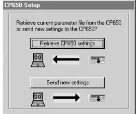
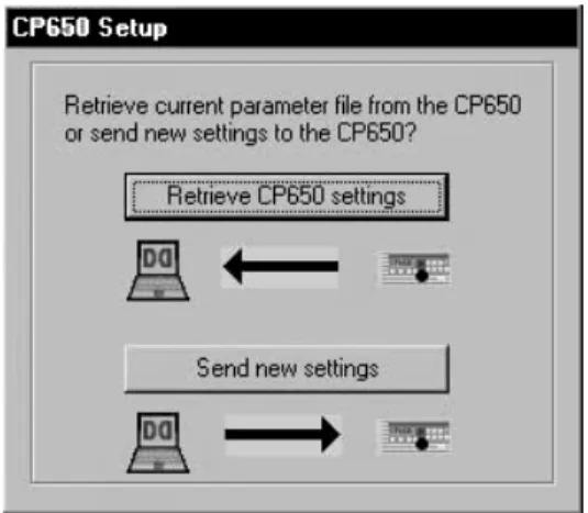
4. You may be prompted to Send or Retrieve the settings. Once connected, the CP650 front panel should indicate External Control Active.
5. Adjust settings using the Setup window.
When Connect is selected from the menu or tool bar, Setup attempts to connect the selected communications port of the PC to the serial interface of the CP650. Upon connection, CP650 Setup automatically retrieves the parameter file from the
prompts to save the current settings (existing parameter file in the PC prior to
retrieving settings from the CP650). If Send is selected, the parameter file that is open in the PC is sent to the CP650.
Figure 1-1 Retrieve/Send Dialog Box
Once connected, the user can adjust settings through the Setup tab property pages. Any changes to the settings, such as moving a slider control, are reflected
immediately in the current operation of the CP650. Changes are saved to the
permanent CP650 Flash memory upon disconnect or exit from the Setup software. If the CP650 is turned off before disconnecting from the Setup software, any parameter changes will be lost.
Note: This is different from the front panel of the CP650 operation. On the front panel, the user must explicitly Save each change via the OK button before leaving the screen for that setting.
When connected, the fader knob is locked out; the Mute button remains functional. Any adjustment marks the open parameter file as modified, and any attempt to exit or open a different file prompts the user to save the current file.
Chapter 2
Setup
Window
The main window of Setup contains the title bar, which displays the application name and the name of the current parameter file, a menu bar, tool bar, status bar, and the tab property pages.
The program opens with a new, untitled parameter file window. Once any setting is altered in the current parameter file, that file is thereafter known as “modified.” Once modified, any attempt to open a different file (new or existing) or exit the application prompts the user to save the current settings. The file can be saved with the same file name that was opened or, in the case of the Untitled file, to a new file name on the PC. The user can work with the software at length in this manner to create files with different configurations, all without ever connecting to a cinema processor.
Note: A number of setup tabs cause the format of the CP650 to change automatically if connected. This change is not reflected on the front panel of the CP650.
2.1 Menus
2.1.1 File
Menu
New (Ctrl+N)
When a New file is requested, the current document is closed (the user is prompted to save if the current document has been modified) and a new Untitled document with default settings is opened.
Open (Ctrl+O)
Opens an existing file from the PC file system, with a filter for *.dby files and CP650 configuration files. When a file is chosen, the user is prompted to save the current file if it has been modified.
Save (Ctrl+S)
Use Save to save the current settings. In the case of an untitled document, there is a prompt for a file name.
Save As
Use Save As to save the current settings to a file other than the file open in the Setup
window. That file then becomes the current Setup file. Revert to Saved
Use Revert to Saved to ignore any changes made to the open file and revert to the previously saved version of that file. A confirmation prompt is displayed. After the original file is loaded, the settings are automatically sent to the CP650, if connected. Previous Files
When the File menu is opened, a list of the most recently used files from the PC file system is displayed.
Exit (Alt+F4)
This command disconnects from the CP650 (if connected), closes the current document, prompts to save (if modified), and exits the application. This operation is canceled if the user chooses Cancel when prompted to save the current modified document.
2.1.2 Action
Menu
Connect/Disconnect
The Connect command is used to establish a serial connection to a CP650. After connecting, this Action menu command changes to Disconnect. The Disconnect
action severs the serial connection and restores the CP650 to normal stand-alone operation. There is no confirmation prompt when Disconnect is selected. After disconnecting, the Action menu command changes back to Connect.
If successfully connected, the prompt to either Send or Retrieve settings may be displayed. Pressing Esc at this time cancels the connection.
Update Software (Ctrl+U)
The CP650 software may be updated from a file on the PC. The CP650 automatically reboots once the software update is complete. Following the reboot, CP650 Setup reconnects and refreshes the CP650 settings to the same state they were in prior to the update.
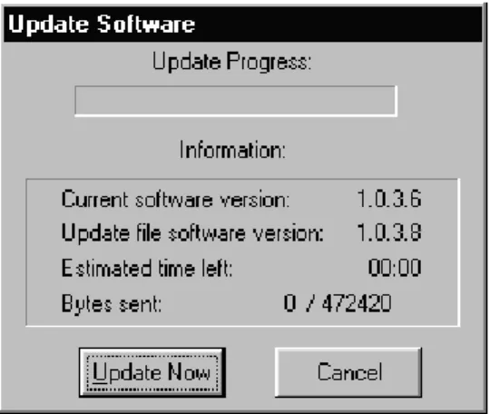
One of the key functions of the Setup software is to update the embedded control and DSP code in the Flash memory of the cinema processor. The update comes as a single package that represents a complete system snapshot. This package is available as a distribution disk or from the Dolby extranet website. Upon selection of the Update Software action, Setup prompts to save the current settings before proceeding. This is not absolutely necessary as the existing parameters are packaged with the new
software; however, it is always a good idea to save settings. Setup presents an Open file dialog to locate the file on disk. The software update file has a file extension of .bin. Upon reading this file, Setup presents the Update Software dialog that displays:
Figure 2-3 Update Software Click Update Now to begin the uninterruptible process.
Caution: The update process should not be interrupted. If the connection is lost during the update process, reconnect the CP650 and restart the software update process. If the software update is not completed successfully before the CP650 main power is turned off, the CP650 will become inoperable.
Mute (Ctrl+M)
The Action menu Mute command is equivalent to pushing the Mute button on the front panel or clicking the Mute button on the Setup toolbar. The command toggles the mute state of the CP650.
Communications Setup
Use the Communications Setup command to select the communications port for serial connection to the CP650. A list of the communication ports is displayed. Only available ports may be selected.
2.1.3 Signal
Menu
The Signal menu allows the selection of the signal to be used for several alignment operations. Certain setup tabs will force or provide their own signal selection options. The current signal selection is displayed in the status bar area at the bottom of the main window.
Program
The available test signals available on the CP650 are:
•
100 Hz sine wave.•
1 kHz sine wave.•
10 kHz sine wave.•
Thump, at one-second intervals. This low-frequency signal is used to check the speaker phase.2.1.4 Window
Menu
Event Log
The Event Log command displays the Event Log window. The Event Log
immediately receives and displays the current event log information from the cinema processor. This log includes a date/time stamp, summary, and description for each event. The source and details of each event are determined by the cinema processor control software.
The Event Log window provides options for printing the Event Log and saving the
2.1.5 Help
Menu
About this Software…
This window displays the revision number of the Setup software, and copyright and license information.
2.1.6 Toolbar
The toolbar includes buttons for quick access to commonly used menu commands, a master fader, and mute control. The toolbar is oriented vertically on the left edge of the window and contains buttons for the following commands:
New
When a New file is requested, the current document is closed (a prompt appears to save the current document if it has been modified) and a new Untitled document with default settings is opened.
Open
Use the Open command to open an existing file from the PC file system. Cinema Processor files have the extension .dby. If a file is chosen, the current file is closed with a prompt to Save if modified.
Save
Save is enabled if the current document is modified. It saves the document, with its current settings, with the same name. In the case of an untitled document, the user is prompted for a file name. After performing a Save, the Save menu option is disabled, as the document is no longer modified.
Connect/Disconnect
Use the Connect command to establish a serial connection to the cinema processor. If successfully connected, follow the prompt to either Send or Retrieve settings as necessary. After connecting, this command changes to Disconnect.
The Disconnect action severs the serial connection and restores the CP650 to normal stand-alone operation. The Setup software does NOT prompt, save, exit, close, or
otherwise alter the current parameter file when disconnecting. The Disconnect
command then changes back to Connect. Upon disconnection, any changes made to the CP650 settings are made part of the permanent Flash memory in the unit.
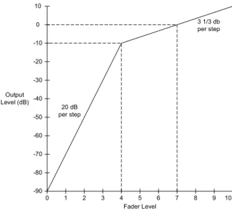
Master Fader
The function of the fader is to adjust the gain of the output according to the Fader Law shown in Figure 2-4. As the Fader increases from 0 to 4 in increments of 0.1, the gain increases from –90 dB to –10 dB. This translates to an increase of 20 dB per whole fader unit. As the fader increases from 4 to 10 in increments of 0.1, the gain increases from –10 dB to 10 dB. This translates to an increase of 3 1/3 dB per fader unit. The fader level is displayed on the CP650 front panel in a two-digit, seven-segment display.
9 -60 -50 -40 -30 -20 -10 3 2 4 5 6 7 8 -70 -80 -90 Fader Level Output Level (dB) 1 0 10 0 10 20 dB per step 3 1/3 db per step
Figure 2-4 Fader Law
The master fader includes a fader level display, a slider to adjust the level, and a mute button that correspond directly to the analogous display and controls on the front panel of the cinema processor. The master fader is enabled whenever the Setup
software is connected, except when a tab is displayed which prescribes that the master fader be fixed at 7.0 (e.g., B-Chain EQ, Room Levels when Pink Noise is selected).
Mute
The Mute button controls the master mute function of the CP650. When the mute function has been activated, the Mute key on the CP650 front panel flashes. When the unit is unmuted, the illumination extinguishes. The speed at which the
mute/unmute functions occur are set with the Fade In Speed and Fade Out Speed
control described in Section 2.12.1.
2.1.7 Status
Bar
This area at the bottom of the main window displays help text for menu options, the current status of the signal source, and the cinema processor link status, Connected
along with the baud rate, or Disconnected.
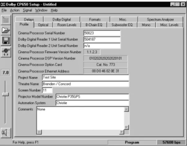
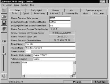
2.2 Profile
Tab
This tab allows the user to enter identifying information about the cinema processor, theatre, and settings file. When a new file is created (at startup or by using File→New), this becomes the top tab, and the cursor is set to the first field for data entry.
The Profile tab is used to record system configuration details. The information entered, along with the setup parameters, can then be saved to a file and reloaded as needed.
2.2.1
Cinema Processor Serial Number
Enter the serial number of the cinema processor to maintain a full record of the system setup.
2.2.2
Dolby Digital Reader 1/2 Unit Serial Number
Enter the digital reader serial numbers to maintain a full record of the system setup.
2.2.3
Cinema Processor Firmware Version Number
Information about the cinema processor is sent from the CP650 to the PC when a connection is made. The Firmware Version Number,DSP Version Number, Option Card, and Ethernet address are then be displayed.
2.2.4
Cinema Processor DSP Version Number
The CP650 module version string is sent from the CP650 to the PC when a connection is made.
2.2.5
Cinema Processor Option Card
Information about installed option cards is sent from the CP650 to the PC when a connection is made.
2.2.6 CP650
Ethernet
Address
The Ethernet address of the cinema processor is read by the PC and displayed on this tab.
2.2.7 Additional
Fields
Enter data for the remaining fields as desired: Project Name,Theatre Name,Screen Number,Projector Model Number,Automation System, and Comments. These entries, along with cinema processor serial number (see 2.2.1 above) and reader serial number (see 2.2.2 above) are saved to the .dby file on disk.
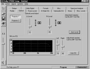
2.3 Optical
Tab
This tab is used to configure the optical settings in the cinema processor, including level and slit-loss equalization. When the Optical tab is selected, the format
automatically changes to allow the appropriate adjustments. Optical adjustments require the use of Cat. No. 69T and Cat. No. 69P test films.
Figure 2-6 Setup Optical Tab
2.3.1 Projector
1/2
2.3.2
Lt Level and Rt Level Adjustments
While running Cat. No. 69T, Dolby Tone Test Film, Lt and Rt levels may be adjusted individually using the associated slider until both green elements are illuminated. This ensures the correct input level to the CP650. Alternately, click Auto Level to allow the CP650 to perform the adjustment.
2.3.3 Auto
Level
Click Auto Level to allow the CP650 to automatically adjust the Lt and Rt preamp gain levels.
2.3.4 Slit-Loss
EQ
The Slit-Loss EQ is an equalization curve that compensates for optical deficiencies resulting from slit-height variations. The curve provides a unique high-frequency boost that compensates for these variations. The level of correction necessary varies by reader type. Typically, reverse-scan basement readers require less adjustment than forward-scan readers.
2.3.5 Left/Right
Adjust the Left and Right Slit-Loss EQ for the most extended high-frequency response without forming a peak. (Click the Left or Right slider to activate the spectrum analyzer display.)
2.3.6 Auto
EQ
Alternately, click Auto EQ to allow the CP650 to perform the adjustment. A dramatic difference in the Left and Right levels may indicate an optical problem.
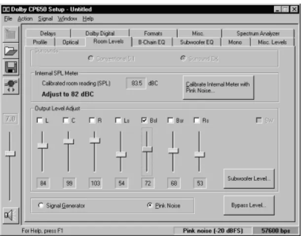
2.4
Room Levels Tab
The current signal selection (Pink Noise, Program, 100 Hz, etc.) is maintained between pages that support the Pink Noise option (B-Chain EQ, Room Levels, and Subwoofer EQ). Switching the signal mode to Pink Noise clears all the channels. With Pink Noise on, all channels are mutually exclusive—selecting any one clears any other selection. To select multiple surround channels, hold the Control key down while making selections. The subwoofer channel is independent in all cases.
Figure 2-8 Setup Room Levels Tab
2.4.1 Surrounds
Surrounds define the configuration of the surround channels for output-level adjust and B-Chain EQ. If operating disconnected, the interface provides two options for surround configuration. If connected and a Surround EX adapter card is installed in the CP650, the selection is forced to Surround EX and the button is disabled. If no
Conventional 5.1
This is the default setting. Dolby Digital utilizes discrete left and right surround channels. During optical film playback, both Ls and Rs are fed an identical mono surround signal.
Surround EX
Surround EX includes channels Ls,Bsl (back surround left), Bsr (back surround right), and Rs.
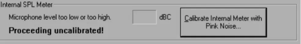
2.4.2 SPL
Meter
The Internal SPL meter can be used to set room levels of each channel, if calibrated. The microphone is connected through either the rear XLR connector or the front Mic Mux connector.
2.4.3 Internal
Calibration
Click Calibrate Internal Meter to enable microphone calibration. Pink Noise is then routed through the center channel. While using an external SPL meter in close
proximity to the microphone, dial in the SPL reading to match what is detected in the theatre. Click Calibrate to calibrate the CP650 and the microphone to the SPL reading. If an error message occurs, indicating the microphone level is too low or too high, check your connections, phantom power, and mic level trimpot located on the front panel of the CP650.
Figure 2-10 Error Message for Failed Calibration
2.4.4 Output
Level
Adjust
This group provides checkbox, label, static value display, and slider controls for each channel as determined by the current Surround configuration. The value always
the setting currently in use in the cinema processor. When leaving the Room Levels
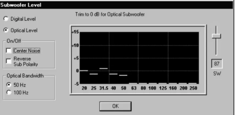
page, all channels are activated. Subwoofer Level
Clicking this button brings up the Subwoofer Level dialog box. This window provides for level trim of the two subwoofer modes, optical and digital. Checkboxes are
provided to turn Center Noise and Reverse Sub Polarity on and off when Optical Level is selected; these checkboxes are disabled when Digital Level is selected.
Note: The reference values are not displayed on the Subwoofer spectrum analyzer until the microphone is calibrated.
Figure 2-11 Subwoofer Level
The initial level setting for the digital subwoofer is 1. The optical subwoofer level is relative to the digital level. If making adjustments to one, check the other.
Center Noise and Reverse Sub Polarity are only available when adjusting the Optical Subwoofer Level.
The Center Noise checkbox corresponds to the Center channel checkbox on the
Room Levels tab. It is initially selected if the Center channel checkbox was selected on the Room Levels tab. If using the Setup analyzer, Center Noise should come up to the 0 dB line. Digital subwoofer level should be trimmed to +10 dB, while the
The Reverse Sub Polarity checkbox is initially clear. It is used to check for subwoofer center channel phase matching. With Optical Level and Center Noise
selected, there should be some adding of the lower frequencies; with Reverse Sub Polarity selected, there should be some noticeable subtraction of lower frequencies. If the Reverse Sub Polarity checkbox is set when leaving the Subwoofer Level
window, a warning message to verify speaker connections is displayed and the polarity returned to normal.
2.4.5 Signal
Signal Generator
The Signal Generator selection is maintained between pages that support the Pink Noise option (B-Chain EQ, Room Levels, and Subwoofer EQ).
Pink Noise
Dolby Level pink noise is used when this is selected. Initial selection of this option clears all output channels. The user must then manually select to which channels to apply the noise. If Pink Noise is selected when switching to a setup tab other than B-Chain EQ or Subwoofer EQ, the noise is turned off, and the signal output is returned to the global signal generator setting.
2.4.6 Bypass
Pressing the Bypass Level button invokes the Bypass Level Adjust window. This places the CP650 in Format 05. Clicking the Bypass On checkbox switches the CP650 into Bypass mode. Adjust the Bypass Level trimpot to match the SPL of the same film in Format 05.
2.5
B-Chain EQ Tab
The B-Chain EQ tab is used to adjust each channel’s frequency response to achieve the desired response curve. This is achieved by using a combination of bulk and one-third octave EQ.
2.5.1 Channels
The current channel name appears at the top of the B-Chain EQ tab, as selected at the bottom of the tab. The solid line on the graph represents the standard ISO 2969 curve. When one of the frequency sliders is selected, the corresponding line segment is yellow. The slider can then be adjusted for boost or cut.
With the cursor anywhere on the B-Chain EQ tab, click the right mouse button to display Copy and Paste functions. These may be used to copy frequency settings from one channel to another.
2.5.2 EQ
Assist
Use this button to apply an approximation algorithm to bring the EQ for the channel close to the desired response curve. Bulk EQ as well as amplifier gains should always be adjusted before applying EQ Assist. EQ Assist is only enabled if the Internal SPL Meter has been calibrated on the Room Levels screen and Pink Noise is activated.
2.5.3 Flatten
EQ
2.5.4 Bulk
EQ
Bulk EQ is used to adjust the bulk equalizers. It is important to adjust both the Bass
and the Treble EQ prior to adjusting the individual one-third-octave bands. Bass Level
The Bass Level is adjustable from –6 to +6 dB in 0.2 dB steps. Use the slider to make adjustments to match the reference curve.
Treble Level
The Treble Level is adjustable from –10 to +10 dB in 0.2 dB steps. Treble Freq
The treble corner frequency can be 1, 2, 3, or 4 kHz, and only applies to the Left, Center, and Right channels. Adjust to match the reference curve as closely as possible. (The corner frequency is fixed at 2 kHz for the surround channels.)
2.5.5 Channel
Level
This slider may be used to adjust the output level of the currently selected channel and is reflected on the Room Levels tab. This does not affect the overall level seen on the spectrum analyzer because the average of frequency bands 7 through 20 is always placed at 0 dB.
2.5.6 Signal
Generator/Pink
Noise
Buttons are provided to select the signal source as Signal Generator or Pink Noise. The spectrum analyzer is only active when Pink Noise is selected.
2.6
Subwoofer EQ Tab
This screen in used to adjust the subwoofer’s parametric equalizer. The three parameters that define the equalizer are Frequency,Q, and Cut. Identify a frequency region that may contain a peak and adjust the parametric equalizer to obtain a flatter response. Note that the vertical axis will be unlabeled if the Internal SPL Meter was not calibrated from the Room Levels tab.
Figure 2-14 Setup Subwoofer EQ Tab
2.6.1 Frequency
The filter’s center Frequency is adjustable from 25 to 125 Hz. The approximate corresponding band is highlighted on the real-time analyzer.
2.6.2 Q
2.6.3 Cut
The Cut value is applied to the center Frequency as selected above, reducing the output level in the Q region. The cut amount is adjustable between 0 and –12.0 dB in 0.2 dB steps.
2.6.4 Graph
When Pink Noise is activated, the graph displays the subwoofer frequency response. With 0.0 dB of Cut, identify the frequency region with the tallest bump. Adjust
Frequency, Q, and Cut to achieve the flattest frequency response.
2.6.5 Signal
Generator/Pink
Noise
Buttons are provided to select the signal source as Signal Generator or Pink Noise.
Figure 2-15 Setup Mono Tab
2.7.1
Mono Level Trim
Mono Level Trim adjustment can vary between –12 dB and 0 dB in 0.2 dB steps. This trim is an offset from the normal playback level.
2.7.2 Mono
EQ
While monitoring film program material, adjust Mono EQ for preferred audio tonal quality. There are 16 steps between the low-frequency and high-frequency settings for the Mono EQ.
2.8
Misc Levels Tab
The Misc Levels tab provides sliders for adjusting the Optical Surround Level Trim and Nonsync 1 and 2 levels.
Figure 2-16 Setup Miscellaneous Levels Tab
2.8.1
Opt. Surr. Level Trim
The Optical Surround Level Trim is adjustable from –3 dB to +6 dB in 0.2 dB steps. This applies to optical surround playback.
2.8.2
Nonsync 1 and 2 Level
The Nonsync 1 and 2 adjustments are controlled by sliders. The number is unitless, and ranges from 1 to 127.
2.9 Delays
Tab
The OpticalSurround Delay should be adjusted so that sounds from the rear of the theatre (surround channels) arrive at the listener’s ear approximately 20 ms after the arrival of sound from the screen speakers.
The Digital Surround Delay should be adjusted so that sounds from the rear of the theatre arrive at the listener’s ear at the same time as the screen speakers.
2.9.1 Surround
Delay
Optical
The OpticalSurround Delay is adjustable from 20 to 150 ms in 1 ms steps. When the Optical delay level is set manually, the Digital delay automatically changes to the same level minus 20 ms, but can be adjusted separately.
Digital
The Digital Surround Delay is adjustable from 20 to 150 milliseconds in 1 ms steps.
2.9.2 Delay
Calculation
The Setup program can calculate and set both Optical and Digital Surround Delay
values based on theatre measurements entered here. Feet/Meters
Measurements may be made in Feet or Meters. Select the desired units. Distance from screen to rear wall of theatre
Average distance between left and right surround channels Values must be between 10 and 140, Feet or Meters.
Calculate
Click Calculate to calculate and automatically set the Surround Delay.
2.10 Dolby
Digital
Tab
Selecting the Dolby Digital tab automatically sets the CP650 to Format 10, Dolby Digital.
Figure 2-18 Setup Dolby Digital Tab
2.10.1 Reader
Delay
manually adjusting the number of perforations when using the Cat. No. 1010 Sync Test Film.
Select Dolby Digital Reader Model
The specific reader model selection is shown in Table 2-1. Selecting a reader model provides an approximation of the correct reader delay. Adjust the delay using the Cat. No. 1010 Sync Test Film.
Table 2-1 Dolby Digital Reader Models
Reader Model Perforations Other (default) 20
Dolby Cat. No. 699/700/701 250
Ballantyne 35 penthouse 247
Century Projector with Component Engineering or Kelmar basement 20
Century 35 mm (SA) penthouse 245
Century 35/70 (JJ) penthouse 309 Christie basement 26 Christie penthouse 250 Cinemeccanica V5 basement 28 Cinemeccanica V5 penthouse 252 Cinemaccanica V8 penthouse 260 Ernemann 15 30 Kinoton FP30 21
Norelco/Kinoton AAll (DP70) penthouse 283
Simplex with Component Engineering or Kelmar basement 26
Perforations
The number of Perforations to delay can be set from 16 to 512 using the up and down arrows. When a reader is selected, as described above, the number of perforations changes accordingly.
2.10.2 Auto Dolby Digital
If Dolby Digital is playing and another film format is selected, the CP650 goes into the selected format, and auto digital is temporarily disabled. Auto Digital is re-enabled when a non-film format is asserted and then a film format is asserted. At that time the system is ready to automatically go into the target format when Dolby Digital audio appears.
Auto Digital Target
The Auto Digital Target may be format 10, or format 13 if a Surround EX card is installed.
2.10.3 Reversion
Mode
Figure 2-19 No Reversion Warning
With Reversion Mode set to Normal, the audio may revert to the analog soundtrack if necessary. A setting of No Reversion keeps the CP650 in the target format
regardless of the condition of the Dolby Digital data.
2.10.4 Auto Surround EX
The CP650 automatically switches to Surround EX mode when all the following conditions are met:
•
A Surround EX option board is installed.•
Format 10 is asserted.•
Surround EX is present within the Dolby Digital data.•
Auto Surround EX is enabled.Figure 2-20 Auto Surround EX Warning
2.11 Formats
Tab
Use the Formats tab to enable and assign Preset Fader Settings, User Formats, and to select the Power-on Format.
Figure 2-21 Setup Dolby Digital Tab
2.11.1 Enable Preset Fader Setting
Click on a box to enable the Preset Fader. Use the up and down arrows to modify the
User 1, User 2, and Nonsync
User 1, User 2, and Nonsync may be set to any of the formats listed in Table 2-2.
Table 2-2 User Formats Number Format Number Format
01 Mono 65 Public Address Surround Channels
04 Dolby A-type 66 Test Tone 320 Hz
05 Dolby SR 70 Video PA (NS1)
10 Dolby Digital 71 Video Mono (NS1)
11 External 6-Channel 73 Video LCR (NS1)
13 Dolby Digital Surround EX 74 Video Pro Logic no Subwoofer (NS1)
20 35 mm Magnetic, 3-Channel 75 Video Pro Logic with Subwoofer (NS1)
22 35 mm Magnetic, 4-Channel 80 Digital Input
42 70 mm Dolby Stereo 81 External Dolby Digital Surround EX
60 Nonsync 1 87 External 6-Channel with Surround EX
61 Nonsync 2 92 Dolby SR (6-Channel In)
2.11.2 Power-On
Format
Select the audio format for the CP650 when power is turned on.
Table 2-3 Power On Formats
Power On Formats Last Format Format 01 Format 04 Format 05 Format 10 Format 11 User 1 User 2 Nonsync
2.12 Misc.
Tab
2.12.1 Mute
The length of time for sound to fade from normal to mute, when Mute is selected, is the Fade Out Speed. The time to return from muted to normal is the Fade In Speed. Both are adjustable from 0.2 to 5.0 seconds in 0.1-second intervals using the
appropriate slider.
2.12.2 Clock
The current PC time and date are displayed. Use the Set CP650 Clock button to synchronize the CP650 clock to the PC time.
2.12.3 Noise
Gating
Pressing this button puts the CP650 into noise gate mode. Click OK to exit the noise gate mode. When in noise gating mode, an automation line controls an internal pink noise source. Pink noise is activated by shorting the automation line-associated pin to ground (pin 12); pin numbers 1 through 8 represent L, C, R, Ls, Rs, SW, all, and Bs channels, respectively.
2.12.4 Rotating
Noise
When Rotating Noise is selected, a five-second pink noise signal is sent to each speaker sequentially. The channel currently running pink noise is indicated in the display. Click Pause to halt the pink noise to the current channel; click Done to exit from the Rotating Noise test.
Figure 2-23 Rotating Noise
2.13 Spectrum
Analyzer
Tab
The Spectrum Analyzer tab displays the frequency response of the selected audio input. When the tab is selected, the default format is Nonsync 1. Only one channel may be selected at a time.
Chapter 3
Event
Log
Choosing the Event Log from the Window menu brings up the Event Log window. The Event Log immediately receives and displays the current event log information from the CP650. This log includes a date/time stamp, summary, and description for each event.
The Event Log window provides options for printing the Event Log and saving the Event Log as text. An example is on the following page.
Cinema Processor Event Log
File C:\My Documents\CP650\Event Logs\ken's unit.txt Date 12Mar2001
Time 14:05:30
System version 1.2.1.4 Setup version 1.2.1.3 Beta
Cinema Processor Option Card: Cat. No. 773 / Cat. No. 794 Cinema Processor DSP Version Number: 020203030403030202 Cinema Processor Ethernet Address: 00 D0 46 00 00 2E
Time Summary Description
---- ---
---13-JAN-00 00:34:07 Startup 12-MAR-01 13:37:37 Startup 12-MAR-01 13:38:41 Startup