Systems Reference Library
Report Program Generator
IBM 1401 Card and Tape Systems
This reference publication contains, language specifi-cations for Report Program Generator for ruM 1401 Card and Tape Systems. The descriptions of the speci-fications sheets and the rules and conventions for writ-ing them constitute the major portion of this publi-cation. Also included, is information about machine processing of the source deck to produce the object program and machine processing of the input data file to produce a report.
For titles and abstracts of associated publications, see the lBAl 1401/1460 Bibliography, Form A24-1495.
Contents
Introduction 3
First Phase of Report Generating. . . .. 10
General Description ... 10
Correlating the Report Specifications ... . . . .. 12
IBM 1403 Spacing Chart ... . . . .. 12
Input Specifications ... 16
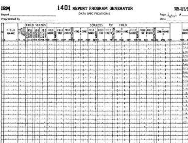
Data Specifications ... 22
Calculation Specifications ... 29
Format Specifications ... " 34 Control Card . . . ... '. 44
Special Feature Specifications .. . . 44
Summary of First Phase of Report Generating 44 Second Phase of Report Generating .. . . 45
Checking the Specifications . . . .. 45
Third Phase of Report Generating ... 46
Program Storage Requirements ... . 46
Fourth Phase of Report Generating ... . . . .. 47
Sense Switches ... 47
Suggestions and Recommendations ... 48
Split Control-Fields in Input Records ... . ... 48
Program Efficiency . . . 48
Description of the General Block Diagrams . . . . 51
Object Program to Process Card Input Files ... 51
Object Program to Process Tape Input Files ... 54
Inserting Subroutines in Object Program ... 58
Subroutine Labels ... 58
Suppressing Total Lines and Calculations 59 Sample Report Documentation. . . . .. 59
Index ... . 74
Minor Revision, Feb-rua-ry 1965
This publication is a reprint of an earlier edition with the format changed to conform to that of the Systems Reference Library. Like the earlier edition, it obsoletes Form J24-0215-1.
Copies of this and other IBM publications can be obtained through IBM Branch Offices.
Introduction
The IBM 1401 Report Program Generator produces
programs that write reports of variable format from card or tape input files. Instead of writing a specific program for each report, the user writes a set of speci-fications which he supplies to the Generator. The process of producing any desired report can be sepa-rated into four phases as shown in Figures 1 and 2.
Object programs can be produced on a 1401 card system equipped with a minimum of 4,000 positions of core storage. No special features are required.
The amount of storage required for executing an object program is dependent upon the complexity of the report specifications. An object program can be
executed on any 1401 system whose storage capacity
will accommodate the object program. Some object programs can be executed on a 1401 system equipped with less than 4,000 positions of core storage. The printer can be an IBM 1403, Modell or Model 2. No
special features are required.
During the first phase (descriptive phase) the user describes information relevant to the report according to certain rules and conventions. He then punches the specifications into cards that constitute the source deck for the Generator.
The second phase is generating the object program in the language of the IBM 1401 Symbolic Program-ming System (see IBM 1401 Symbolic Programming
System, Form J24-0200). In phase three the 1401 SPS
processor or the 1401 Autocoder (see Autocoder for
the IBM 1401, Form J24-1434) processor converts the
symbolic object program into the machine-language instructions required to write the report. Before the object program is converted from symbolic language to machine language, the user can incorporate any of his own subroutines into the program and then as-semble the augmented object program.
The fourth (final) phase of report generating is the execution of the object program to produce the report. The input data must be in either card or tape files.
Object programs produced by the Report Program Generator can process magnetic-tape' input files having:
1. Fixed-length records with fixed blocking.
2. Variable-length records that are unblocked (single-record blocks).
The maximum allowable block-length for input tape records varies with the size of the object program ~~n~r-L~..l Aft~ ~ L ' t . b1 d
ot: It: cut:u. t:T an oujec program IS ass em Ie in
machine language) the user can readily determine how
much storage remains for the input tape-record block (see Third Phase of Rep01t Generating: Program
Stor-age Requirements).
A tape file is the data contained between tape marks. A tape reel can contain any number of tape files. All or only some of the files on a tape may be considered part of the input data to a program. Thus, the ability to process or bypass files as well as the ability to restart the program after an end-of-file condition has been sensed are included in the generated object program. Because the program always halts on an end-of-file condition, input data may be contained on more than one reel of tape.
If the user specifies that there is a header label at the beginning of an input tape, the generated object program bypasses the first record on the input tape, including any tape mark following that record. The user can choose to have the label processed if it meets the specifications for record and block size pertaining to the entire data file.
As mentioned earlier, the output of the object pro-gram can be a printed report, punched cards, tape records or some combination of the three. Card input can be processed to produce printed and/or punched output. Tape input can yield tape output as well as printing and punching in any combination. Only un-blocked, fixed-length tape records no longer than 132 characters can be produced as output. Although these records must compose a single file, that file can be written on more than one reel of tape. (The generated program halts on an end-of-reel condition to allow a new tape to be mounted.)
This bulletin is concerned mainly with a description of the first phase of report generating, i.e., stating the specifications of the report and compiling a source deck. Accordingly, the descriptions of the sheets on which the specifications will be written and the rules and conventions for writing them constitute the major portion of this bulletin. Also included, however, is in-formation about machine processing of the source deck to produce the object program (phases 2 and 3) and machine processing of the input data file to produce a report (phase 4).
Requests for the Card or for the Tape Report Pro-gram Generator proPro-gram deck and write-up (which includes program listings and operating instructions) should be made to the local IBM sales representative
or sales office.
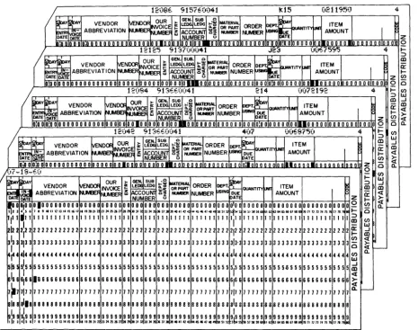
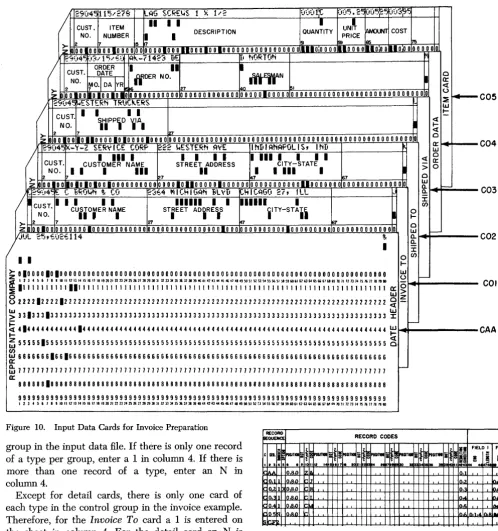
Figure 3 shows a few input cards for a report pro-duced using the IBM 1401 Report Program Generator.
Format Specs.
Input Specifications
Sheet
Specifications Source Deck
Card Report Prog. Generator Processor Deck
Symbolic Prog. System Deck or Autocoder Deck
Object Program in Symbolic
Language
Object Program in Machine
Language
Specifi cations Source Deck
1401 Data Processing
System
Object Program in Symbolic
Language
1401 Data Processing
System
Obj ect Program in Machine
Language
Card Report Prog. Generator Processor Deck
Symbolic Prog. System Deck or Autocoder Deck
(
III1111
~
te---I\
Input: Data IIIW~~~~~~~ Processing . File W
(In~l~ata
f
'
;ystem ",
L...-_ _ _ _ - - - l~I _ _ _ _ _ ~~ / / ~~
I _
Re:~
I
(~~"~~,~IIIIII
[:J
I
Cam. SpecifiedWW
Format Specs.
Input Specifications
Sheet
Specifications Source Deck
Tape Report Prog. Generator Processor Deck
Object Program in Symbolic
Language
Object Program in Machine
Language
/
Specifications Source Deck
1401
Data Processing
System
Object Program in Symbolic
Language
1401
Data Processing
System
Object Program in Machine
Language
1401
Data Processing
System
/
/
"'
...
---... ...
--...Cards Specified
Figure 2. Generating a Report on a 1401 Tape/Card System
Tape Report Prog, Generator Processor Deck
or
n
12;)8.. 9I,(fO;)41 kl5 (021195') 4~t
':f VENDOR VENDORNVOIC OUR ~~
LEDG t:~ Q MATERIAL ORDER ~EP't~
ITEMI
[ENm
~g
ABBREVIATION~~UM~ ~
ACCOU_1I£f~~
:r::J
M.M3ER~N<iIUE ~IT'I"""
AMOUNTDATE ~TE NUMBER (.) DATE Z
l1I~nDln n nln:D 0 D D DOD D D DID DOD 0 0.0 10 0010 O •• OOIOJLO !LI.IIO_D OJlO Dill 0 0 000 D 0 0 D n.-nnlilflflifil D D 0 0 OlD D D 0
n
12125 9137;)(';)41 .r.;:; (o(~ 70;<;5 4 ... ::::>~; OUR I~ SUB. Q ~I tlAl ~ ~ m
VENDOR ivENDOR NVOICE ~ LEI)(; lL~ OR ~~T ORDER DEPT. -buANTITY~ ITEM 1 P. (r ~ - ABBREVIATION o,,--=>=>Nl.M3EF ffi ACC~]] ~1 NlMB NUMBER~SING~E AMOUNT ...
DATE DATE NUMBER (.) DATE Z (I)
O!OOOOOOOOOOOOOOOOOOOOOOOOOOOOOOOIOII.OOOOOOOOOOOOOOOOOOOOOOOooo •• onOOO~OOOOOOIOOOO Q 0
n
12(.t<4 "I 3f.,o.;)D4 1 214 ;)(072192 4 ... (I)::::> w
~~
VENDOR~<X>IN~ ~ I~.m .i~=
ORDER~~..-.r<~
ITEMI
~
a) ...J
a:
m<l ~ ABBREVIATION ~BEFIt.JI.Jt.~ ffi 1~~croU..N1 ~1 NlNIER NUMBER ~G DUE AMOUNT ~ ... ~
DATE DATE MBER (.) DATE Z (I)
<l
o 0 0 0 0 0 0 0 0 0 0 0 0 0 0 0 0 0 0 010 00 0 10 0 0 0 0 0 010 0 III 0 0 0 0 0 0 0 0 0 0 0 0 0 0 0 0 0 0 0 0 0 0 0 0 0 o n 0 0 0 0 0 0 0 0 0 0 0 DTo 0 0 0 Q 0 0.
n.
12D42 0;1 3E.6Du4 I 4(.7 <',.5675,. 4 ... (I):::l W
~~, A VENDOR ~D()f; OUR ~ IGEoojSUB LE LEDG t-=~ ~ATERIIU. Q ORDER DEP't. ~ ':f ITEM a) ...J
a:: m
~~
i
ABBREVIATION •••• ..-.= INVOICE~
ACCOUtiI~~
: : NUMBER~
DUE UANTml-N1 AMOUNTI
... <lDATE ~"fVtYlDL.l" 1&1 NUMBER i3 pATE (I) ~
DiD 0 0 0 0 0 0 0 0 0 0 0 0 0 0 0 0 0 0 0 ODD' Dolo 010 0 010 0 110 0 '0 0 JI 0 010 0 0 0 0 010 0 010:1010 {) 0 0 nln nll-.--oo nlilion n 0-n-o oTii n n
ts
l 0 10.1---,){-18-E-;) '(1)
~
~ OUR )o~.~~
... w
~~~ ORDER DEPT ITEM ~ ::::> ...J
VENDOR jvEND()f; INVOICE ~ LE LEDG lL~ QUANTm ~ a) m
IN ABBREVIATION NlA.:x:1: ffi ~COUNl ~1 NUMBER NUMBER ~ING ~~ie AMOUNT ~ a:: <l
DATE Il'IVVEX:r NUMBER (.) Z ... ~
I~OO
0,0001000 00000 00000000000000000 0 0 0 0 0 00000000000000 0100 00000 00 00000000000000000 02 (I) <l0. r
-123 4 ~ 6 I • , 18 II '2.3 ••• 5161111" 282':r. 2314 25 26 21281! JO 3' ~ 1134 ~ 3& 31 JI 394041424444546414845051S:
sis.
~ ~5)58596j 6'62 oil 6465 66 6161 ~ 10 II 12 13 " 15 ~ II IS ~I. ... 0',II
1'111111111111111111111111111111111 11111111111111I,"
11111 11 11111111111111111 1::::> m (I)2:2 2 2 2 2 2 2 2 2 2 2 2 2 2 2 2 2 2 2 2 2 2 2 2 2 2 2 2 2 2 2 2 2 2 2(r w
~'22
22222222222222 2122 22222 22 22222222222222222 ...J... a)
3133 ~3333333333333333333333333333333333 33333333333333 313-3 33333 33 33333333333333333 3 -(I) <l ~
~~4
0 <lI---~4444444444444444444444444444444444 44444444444444 4144 4444 4 44 44444444444444444 4(1) 0.
~5555555555555555555555555555555555
5155lLI
5155 55555555555555 55555 55 555~5555555555555 5~
~I&I ~6611666666666666666666666666666666 66666666666666 6166 66666 66 66666666666666666
I
6~ «7~7
717 7 7 7 7 7 7 7 1111 7 7 7 7 7 1 1 7 7 7 1 7 11 7 7 1 7 7 7 7 7 11777777777777 7177 77 77 7 77 777771777777777717~
r-ala a ~188a88a888aa8a88888888888888888881 88888888888888 ala 8 88 a a 8 88 8E8888888ii8888888 8
~Ig g 9'9 9 9 9 9 9 9 9 9 9999199999999 9 999 999999999 99999999999999 ;~; I 99999 99 !!!!~!!!~~!!!!~~!
!
.• 12l 4h i I. '.011.2.3.4.5161111.9282.2l2l1425262128251303.323334313&31J1 39 • • I4243~45 • • I4I"50~'5Z 5651581560 '62
[image:6.624.64.530.61.428.2]MONTHLY EXPENSE DISTRIBUTION REPORT
REPORT DATE 07-18-60 PAGE
OUR DATE AMOUNT AMOUNT
INVOICE AMOUNT BY BY
NUMBER MO DAY ACCOUNT DEPT
*** DEPT. NO. 0"1 ** GEN. LEDGER NO. 913
* SUB. LEDGER NO. 660
120"2
"
07 687.501208" 2 1" 721.92
1,"09."2 * * SUB. LEDGER NO. 700
12125 11 23 675.95
675.95 *
2,085.37
** GEN. LEDGER NO. 915
* SUB. LEDGER NO. 760
12086 12 15 2,119.50
2,119.50 *
2,119.50
",20".87
L
__________ . ___________
J
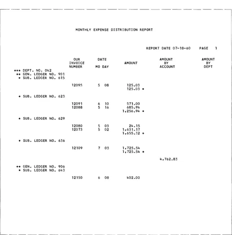
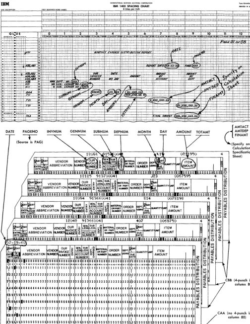
Figure 4. Monthly Expense Distribution Report (Part 1 of 3)
MONTHLY EXPENSE DISTRIBUTION REPORT
REPORT DATE 07-18-60 PAGE
OUR DATE AMOUNT AMOUNT
INVOICE AMOUNT BY BY
NUMBER MO DAY ACCOUNT DEPT
*** DEPT. NO. 042 ** GEN. LEDGER NO. 901
* SUB. LEDGER NO. 615
12095 5 08 125.03
125.03 * * SUB. LEDGER NO. 623
12091 6 10 571.00
12088 5 16 685.94
1,256.94 * * SUB. LEDGER NO. 629
12080 5 03 24.15
12073 5 02 1,631.17
1,655.32 * * SUB. LEDGER NO. 636
12109 7 03 1,725.54
1,725.54 *
4,762.83
** GEN. LEDGER NO. 906 * SUB. LEDGER NO. 643
12150 6 08 402.00
~--- - - - -- - - -- - - --
[image:8.613.53.516.95.563.2]REPORT DATE 07-18-60 PAGE 2
OUR DATE AMOUNT AMOUNT
INVOICE AMOUNT BY BY
NUMBER MO DAY ACCOUNT DEPT
12090 5 23 331.96
12106 7 03 95.65
829.61 * * SUB. LEDGER NO. 650
12093 8 09 806.00
806.00 *
1,635.61
6,398.44
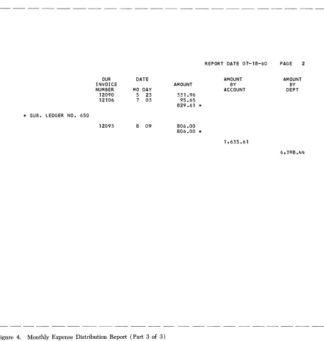
Figure 4. Monthly Expense Distribution Report (Part 3 of 3)
[image:9.612.77.534.94.574.2]First Phase of Report Generating
General Description
To generate an object program, the IBM 1401 Report Program Generator (RPG) requires certain informa-tion. The information answers these questions: 1. What are the characteristics of the file from which
the report data is obtained?
2. What type of information is to be extracted from the input file? From which records can these source fields be obtained?
3. What types of calculations are to be performed during the execution of the object program? How are the results of these calculations to be manipu-lated?
4. What is the format of the report? What headings and constants must it contain? How should the data composing the report be edited?
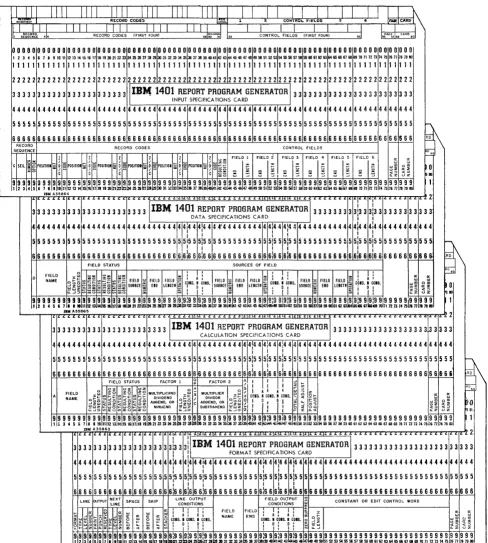
As shown in Figures 1 and 2, four forms are re-quired for writing the report specifications. The forms contain answers to the preceding questions. The in-formation is punched into cards (Figure 5) with one card punched for each line. These cards comprise the specifications source deck. The RPG program proc-esses the source deck to produce the object program.
Before the actual report specifications can be writ-ten, the user must have a clear image of what he wants as the final product. That is, he must know the contents of each line of the report, the spacing be-tween lines, and the positioning of the information within each line of the report. He uses the IBM 1403
Spacing Chart, Form X24-6436, before writing
specifi-cations. Preparing this chart consists of laying out the complete format of the report to obtain a pictorial representation of the final product. Although no cards for the source deck are punched directly from the entries on this chart, the pictorial representation serves as a guide to completing the four specifications sheets.
It thus plays an important role in writing report specifications.
The spacing chart and the four forms required dur-ing phase one are listed here in the order in which they are used. A brief description of the functions of each form is also given. Later sections will explain their use in more detail.
1. IBM 1403 SPACING CHART, FORM X24-6436
This chart was described earlier as the form on which the user's image of the report is projected. Define the position of each field on each line of the report and include constant information, headings, and editing symbols, where applicable.
2. INPUT SPECIFICATIONS, FORM X24-1336
A description of the data file, from which the informa-tion required for the report will be extracted, must be specified on this form. Describe each type of record in the data file, with its distinguishing record codes and control fields.
3. DATA SPECIFICATIONS, FORM X24-1337
On this form the user lists the data fields necessary for processing the report. These data fields may be output fields or factors in calculations. Each field described is associated with the input record or records that contribute to it. It is also associated with any condi-tions that govern the processing of those input records. Any number of fields from one or more input records can be listed as the sources of a data field. The input sources can be added and subtracted as well as moved to the data field. Furthermore, the user can state that the status (positive, negative, zero, or blank) of a data field will be needed to govern subsequent process-ing. For example, a line can be conditioned to print only if a particular data field is positive.
4. CALCULATION SPECIFICATIONS, FORM X24-1338 Although a limited amount of calculation is available through entries on the data specifications sheet, the
calculation specifications sheet must be used for more
extensive calculations including multiplication, divi-sion, and comparing. This form accommodates calcula-tions on data fields described on the data specificatwns sheet, as well as constants and the results of previous calculations. Half-adjusting, position-adjusting, and the conditions governing the performance of a calculation can all be shown on this sheet, Furthermore, the user can define status conditions based upon the sign of the calculated result or the comparison of two fields.
5. FORMAT SPECIFICATIONS, FORM X24-1339
I
I
RECORD CODES l<'o·.~. 1 2 CONtROL rIELD$
II I I I I I I I I I
RECORD CODES (FIRST FOIlR) 29 ':,S.CO;~ '-" .. ' - -_ _ --'C:..:.0:.:.cNT-"R.:..:OL::....:.c.FIE=.:L:.::cDS=-..;(:.:.cFI.:.:;RS:.:.cT --,FO:..:.U":..:.) _ _ _
=
..
I000000000000000000000000000000000000000000000000000000ooooooooo~oooooooooooooooo
123456789ro"n~U~~"aa~~~nu~~n~~~~~~M~~D~~~~~~«~~U~~~~~~~~~~~~OO~~~ ~~~~~mnnn~~~nnn~
11111111111111111111111111111111111111111111111111111111111111111111111111111111
22222222222222222222222 2 2 2 2 2 2 2 2 2 2 2 2 2 2 2 2 2 2 2 2 2 2 2 2 2 2 22 2 2 2 2 2 2 2 2 2 2 2 2 2 2 2 2 2 2 2 2 2 2 2 2 2 2 2 2 2
3 3 3 3 3 3 3 3 3 3 3 3 3 3 3 3 3 3 3 3 3 3 311B111401 REPORT PROGRAM GENERATOR 13 3 3 3 3 3 3 3 3 3 3 3 3 3 3 3 3 3 3 3 3 3 3 3
INPUT SPECIFICATIONS CARD
44444444444444444444444444444444444444444444444444444444444444444444444444444444
55555555555555555555555555555555555555555555555555555555555555555555555555555555
6666666666666666666666666666666666666666666666666666 6 6 6 6 6 6 6 6 66666666666666
Sll!!!
S~~~~~~E RECORD CODES CONTROL FIELDS
~ 1 1 1 1 1
,I;
1 ~ ~ FIELD I FIELD iI
FIELD 3 FIELD 4 FIELD 5 FIELD 6 a: 0:C SEQ. ~ ~ POSITION:; ~ g: POSITIOR ~ ~ g POSITION:; 0 g POSITIOI :;; ~ g POSITIOI 6 ~ g POSITION ::; ~ g ~ ~ ~ ~ ;= ~ !: ~ ~ ~ ~ ~ 0 ~~ zf~ ~~ ~~~ :E~~ -f~ or~~~~ ~ ~ ~ ;, ~ ; ~ ~ ~ ; ~; ~~ ~~ ~oo
9999999999999999999 9 9 99999999999999999',9 9!9 9 9 9 9 9 9 9 9 9 9 9 Sl9 9 9 9 9 9 9 99999999999999
gts9m
11 2 3 4 5 6 7 a 9 10 " 12 13 14 15 16 17 \I a ~ 21 24 ~ ~ ~ j iI!l 30 31 02 ~ M ~ ~ 37 ~ 39 ~~1 42 ~ « 45 ~ 47 48 49 ~ 51 ~ ~I~ ~ 5& 57 58 59 60 61 62 ~.64 65 66 67 68 69 70 71 12 73 1475 7& 7J 78 79 BO
IBM A35864
... .... I .. L L L L . . . I... .. ... 1 . . ! .... I . . i ... ~LL L 2
333333333333333333333 3
311B~
1401 REPORT PROGRAM GENERATOR 1333333333:333:333333333333DATA SPECIFICATIONS CARD I
I
4444444444444444444444444444444~44~44f4444444444~44~4444444444444~44~44444444444
: I I I I
I
5555555555555555555555555555555155515555555555555515 5 5:5 5 5 5 5 555555555:5551555555555555
I I I I I I
66 6 6 6 6 6 6 666 6 6 6 6 6 6 6 6 6 6 6 6 6 6 6 6 6 6 6 6
is
6 Sl6 6 S 6 6 6 6 6 6 6 6 6 6 6:6 6 616 6 6 6 6 6 6 6 6 6 666 616 6 616 6 6 6 6 6 6 ~~FIELD STATUS SOURCES OF FIELD
L L L L L I ' ' ' ' ' I ' ' L L < C L L ' ' L L I L ' ' L L _ .. L . . . L . . . · . . . 2
3333333133333333333333 3
311B~
1401 REPORT PROGRAM GENERATOR 1333333333333333333333333I
CALCULA TlON SPECIFICATIONS CARD
4444444444444444444444444444444444444444~44~44~444444444444444444444444444444444
I I I
55555555555555555555555555555555555555551555:555:5 5 5.5 5 5 5 5 5 5 5 5 5 5 5 5 5 5 5 5 5 5 5 5 5 555555555
I I I
6 6 6 6 6 6 6 6 6 6 6 6 6 6 6 6 6 6 6 6 6 6 G 6 6 6 6 6 S 6 6 6 S S 6 6 6 6 6 6:6 6 6 i6 6 6:6 6 6 6 6 6 6 S 6 6 6 6 6 6 6 6 6 6 6 6 6 6 6 6 6 6 6 6
6llW
FIELD STATUS FACTOR 1 ~ FACTOR 2 ~
I : :
~ in~ ~ ~ ~ 2 ~ ~ MULTIPLICAND :;:: ~x MULTIPLIER ~ ~ ~II A I A I ~ 3 Z
A ~~~~ ~!:::::~~E~~!::~~~ DIVIDEND ~~I DIVISOR o~~+COIll.tlCO.D.IICO.D'::J<~~ ~ ~
g~~ ~ ~~
§
~~ ~ ~~ A~~~~'N~R g~~
c:~~i:~~E~~ g~~ ~I!
Ii I!
~ ~
u
n
~ ~ ~
I~I~ ~ ~ ~ ~ ~I~ ~ ~ ~I~~I~I~ ~I~I~ ~,i~~!;~~~i:~~ ~;!!i~iil!~ !~~!~k~!!ii~,~!,!!!~~~~~~!!!!~!! ~~ ~~!~if!ml
1mY A35863
iL L L iL L L L L L , .L L L :L I .. .. .. .. .. .. .. .. .. .. .. .. .. .. .. .. .. .... L 2
3333333333333333333 31a 3
3ijllBM
1401 REPORT PROGRAM GENERATOR \ 3 3 3 3 3 3 3 3 3 3 3 3 3 3 3 3 3 3 3 3 3 3 3 3I I FORMAT SPECIFICATIONS CARD
I 1~~~---.-~~-r~~~rT--~~~~
44444444444444444444~44~44~44444444444~44~44~44444444444444444444444444444444444
I I I I I I
555515555555555555555:555:555\5555555555551555:555:5 5 5 5555555555555555555555555555 5 5 5 5 5
1 I I I I I I
6 6 6 6 5 6 6 6 6 6 6 6 6 6 6 6 6 6 6 6 i6 6 61s 6 616 6 6 6 6 6 6 6 6 6 6 6:5 6 616 6 616 6 6 6 6 6 6 6 6 6 6 6 6 6 6 6 6 6 6 6 6 6 6 6 6 6 6 6 6 6 6 6 6 6 6 6
LINE PUTPUT ~~~; SPACE SKIP L~~END~~~:~T F~~~DI~~g:~T ~ CONSTANT OR EDIT CONTROL WORD
... !I~o::: 8 0: LLI td : ! i ; ! : ! : FIELD FIELD I ~ I !: ~ :J: cc 0:
<t ....J W 'J: > ...J UJ 0::: 0: 0: cr: ~ I A I A I NAME END I A I A. I 0) I- W I.LI
:i w ~I~I~ u :5 1.1.1 LL.I ~ 0 W 0 l.I.I U COlO. I COlD. I COlO. COlD .• C.DIO~ • COlD. 0 ~ ~ ~ ~ ~ ~
~ ~ ~I~ ~ ~ ~I~ ~ ~ ~ ~ ~ ~ ~! ~: ~ ~
!
~i
~ i ~ ~ ~ ~ i ;S ~f919 9!919 9 919 9 9 9 999999999:9 9i919 Sl9j9 9 9 9 9 9 999999:9919:99191999999199999999999999999999999 9 919 9 9 9 9
Ii 2 31el5 6 711 11011 121314 51117 ta 1~i21 22123i24251i1Zl 28 29303132~ 34b5~ 31Ii1i3940kll42~k4i45 46 748~~51 ~~ ~~ ~ 57 58591i961626364~6667~69 10717273 74 1517& 77178 n 80
IBM A35862
[image:11.613.76.564.55.597.2]Correlating the
Report Specifications
When completed, the five forms are an interrelated statement of the problem being specified as shown in Figure 6. The spacing chart represents the output lines described in the format specifications sheet. The same line names are used on both forms.
The names given to various input records on the input specifications sheet are the same names used as
field sources on the data specifications sheet to indi-cate the record from which a data field is taken during report writing. Each input record is assigned a unique two-digit number called a resulting condition number. During report processing, this condition is fulfilled whenever a record with the record codes specified for that resulting condition is present in the input area. The fulfillment of such a condition can govern the processing of a source field in the data specifications, the performance of a calculation specmcation, the placement of a field within a line or the output of that line as stated in the format specifications. The fulfil-ment of a resulting condition can be compared to the transferring of a selector on an accounting machine during the presence of a particular card. It can also be compared to the setting of a programming switch on a stored-program machine to indicate the presence of a particular record type. The change of a control field
specified for input records can also govern the process-ing of source fields (e.g., to provide group indica-tion ), the performance of a calculaindica-tion, the printing of lines, and the punching of cards.
Thus, the input specifications describe the kinds of records in the input data file according to the cod-ing and control fields that are significant in these records. These specifications inherently determine many conditions for processing the data to be ex-tracted from the input file.
The fields named on the data specifications sheet can be used as factors in calculations or as fields in lines. The fields named on the calculation specifica-tions sheet can also be placed in lines on the format specifications sheet. Sometimes the status of a field (positive, negative, zero, or blank) is important in the processing of that or other fields. It may be that cal-culations should not be performed on zero or blank fields or it may be that a field should be printed in different positions depending upon whether it is posi-tive or negaposi-tive. Perhaps a line should be printed only when a certain field is not blank. Whenever the status of a field is important to processing, that status can be specified on the data sheet or calculation sheet beside the field name. Then, the status is assigned a unique two-digit resulting-condition number to represent it. The fulfillment of that condition during processing can govern further processing, as just indicated.
Thus, fields from the data and calculation sheets contribute to the lines on the format sheet. Conditions representing the presence of a record in the input area, the change in control between that record and the previous record, or the status of certain fields that have been processed can govern the presence and placement of fields within a line or the printing, punching, or writing on tape of that line. Furthermore, a line can be included in the output because the out-put conditions were met for a previous line. This re-lationship is described by a next line specmcation on the format sheet.
Considered together, the five forms represent the input file, the significant data fields within that file, the manipulations necessary to obtain the required output fields, and the line formats in which the fields are to appear.
This summarizes briefly the elements that enter into report specifications during the first phase of report generating. In the sections that follow, each of the forms will be examined in greater detail. The rules and conventions governing report specifications are presented. Two sample applications are used to illus-trate pertinent parts of the description. For complete documentation of these sample reports, see Figures
52
to65.
laM J
403 Spacing
ChartThe purposes of laying out the report on the IBM 1403
Spacing Chart are:
1. to establish the positions at which the various data will be printed, punched, or written on tape, as well as to indicate the spacing between printed lines, and
2. to assign each line a unique identification code representing
a. the type of line,
b. the level of the line, and
c. the number of the line within its level.
Layout of Lines and Fields
The numbers across the top and bottom of the spacing chart represent the IBM 1403 print positions. The
IBJ.1
INTERNATIONAL BUSINESS MACHINES CORPORATIONIBM 1403 SPACING CHART PRINTED IN U.S.A
FiElD HEADINGS/WORD MARKS 6 Lines per inch
-TnT -nrTII '11 I rr I ITT 11 I I I II I I 111111111 I II II I I I I 111111111 111111111 TTl In III 11ITI I I II T n r l l l l ' I I l r l l l l i Ie
- - iTT '-nITI r l IT ffl IT I I I I I I I II 111111111 1 II/IT I 1 I I II I I I I 11 TfT I II1I I III
jTTITTTl I1TTITITT ifTTTTflf TTITrTTTT -Tlf filii I l i l l '1 TTf 'rnnTn'f TTlTl1 Ifl I ITT I
",?
~:~-~""-~
o 1 2 3 4 5 6 7 8 9 10 11 12 13-~ iT':~ ,L
=1
'l'l'lr"l'
01112:'I~'I""
0'1 ';';'I'I'111
'r
0~'I':'I';1:'"
OIII'I'i'i"r'i'
~I
i':'I""":':'
011['1'
'll
I
11':' 0
1
1[';':4';'[1
1'1'
0,1['1'1'1'
Il'
'fI'I'I"]'
'j'1'lr'I'
Oltl"'~~'
"I'
"T' ,-,TcHF'lffi - '
r,+
:-m
,i,I
!~
' " :t!
~ tI
! I i ! '~I ~' ,"!~
III 1-I
I' I
! i'I
I
~'~i
1 '!! :
I '"
'{~!;
I'
I k" ~~ii
~ ~
r
1 ~ i d 1I
II
r
0, ! I 11 'I
j'I
j'~
I II
I .' , ,wi 1-"- lett '4..1.... ~ 3
I,
I ,Ii'l ' p.1I.11 III I ' 'iX,X,OI·>e 1-:, ' t ,"X.
I . It·· . . . i IA'r~; j I-e~ I' - HfTj - :
I,
!
I:
Ii!
I
i
rl
I~ri
i:
'III i
;~ *"~o*-Il!
I
i~~Jf~:o~~
I,
I
i
~~~: ~ol
i:III~,
,'rl,/x,
0
III
~1~,~Jdlo,
1111
II .
'"I: e t . - .... ,~ •
IBM
1401
REPORT PROGRAM GENERATOR FORM X24·1336PRINTED IN U,S,A,
Report. INPUT SPECIFICATIONS Poge~ of
-Progrommed by Date
RECORO RECORD CODES
(CONTROL FIELDS)
SEQUENCE ,..-..
( C
Ii ~~ FIELD I FiELD 2 FI ELD 3 FI ELD 4 FIELD 5 FI ELD 6 CARO
)~POSITION 1
~t
~t
~t ~t NUMBERSEQ, ~f ~POSITION ~ OSITION ~posmON ~POSlTrON ~POSITION :; 'D.i~ ~~
~
.t
es ~ ~Q I~
C C "'f Z i!
~r;
~ l~
~ ; ~ I;'t fri 4 5 6 8 9 '0 1112 14 1!5IS .'16 20 2122 2 4 26 79 )!s 30 32 3~ 34 3536 38 39";'~ 46 7~8 9 51!52~3 54 56575 59 61263 64 66 768 69 71172 73 475b'e 80
_1.-1- I t . - - L+L
_L+
__ L ... L' _.L l---.l~ f--t-....L.l .. -1.-_ L..L~ f - -0, I.~OI I I r y I
I
DATA S
Dr;;~ ~~~
FIELD AATUS ~. I~VA'"\SOUR~~~ OF F.l.LD
. :
-~~~
H
~l
fiELDI
FIELD FIELD 52 CO NO ~ CO NO FIELD ~ FIELD IELD ~ ( A \FIE o ~ FIELD FIELD ~I A CARDPECIFICATIONS ~A:-V ~~~ ::;:B;ii: ~~ ~~ SOURCE END LENGTH ~ 0 . SOURCE ~ END NGTH ~ COND,~ COND, SOU E ~ END LENGTH ~i COND, ~ COND NUMBER
:;;~8 ~~ ~8 '--"iii I~I\"~ ~
'6~~"
~ ~ 7~'. 2 7 9 10 II 12131 '516 7181920 22234 2627 29~' 3334 3637 391<, . . 6!5759 6 . , 63 65 67 8 7071 759 90
--L.L ..l.
L L
r'
'Jf~
Lt+-L
L L --' 1
-'--l...L..L.. ~1.l.0
LL_ _.J...L.. ~ I ( _-1 ,.1 -_.J __ L - -t f-L +-'~ e-.l--'-- L.l. L L +_1 L l . I 92.l.°
CALCUL
FIELD STATUS FtCTOR I ~ F4cTOR 2
it
A A\~
f
~
V;
~ ~~~
!~I
n
II
~,,"i=§~~UJ
~I
9 CONO.NCONO,NCO, ~ CARDI~
~AI~~Y u:~~ ULlIPLICANO ~~~
0\
0 0 NUMBER
A~~EI~~,N~R c;:~~ ~ A~:~~S~~R c;: ~
ATIION SPECIFICATIONS " 7 9 , 1112131151671819 ~.,. 29~3. 383940 42~3t4546 4 4 051 525:554 7578 90 L.1 .L-L._L .... L 1 ..l. .. -.1_ 1 o I 0
II J ... l...L...L..l _~.L _ --L..L __ ."~ - ·i....L
I
.:. o 2 0
c_~._
r----...,
LINE ~UTPUT ~~EXT SPACE SKIP LINE OUTPUT
6
FIELD OUTPUTCONST NT OR EDIT CONTROL WORD LINE CONDITIONS 1\ CONDITIONS . /
0
-R
Tl~ !~ : A IE Ie A
1
CARDM ~::; dl~
i
~
IJ;
I~ ENP FIELD NUMBERI~~~
:r'i'jlfE COND N CONO, N OND CON N CC D, N COND, LENGTHIfi ie I::!
~~
o 0 D D, i 6 7 II 12131415 1617 18 I 9 0 22 256 299 34 5 3738 4041 4344 46
.
50' 7578 9CFORMA T SPECIFICATIONS
If\
J~
) , ~ , 1 +L t j I' .Ll .. L L.l_ .. L.t + +L __ +.L L o I°
( +-'-_+.J. _ _ L.l
0,2,0
.~
I I,-;+t
.. ~ - ---_ .. ..L -1--- ' I 0,3,0,.... ~
Ij::,..
~.
I-j
CD
:--:t
Cf) 'c:l
llJ ( j
s·
)q
(j
::r'
~
I-+>
0
I-j
~
§ §:
'<
I:i:l
l><
'c:l
~
CI'l
CD
tj
tij.
r-I"
I-j
5='
g.
6·
r:s
::0
CD
'c:l
a
IB~ 'NTERNATIONAL BUSINESS MACHINES CORPORATION Form X24-6436
PRINTED IN U,S,A,
IBM 1403 SPACING CHART
LINE DESCRIPTION FIELD HEADINGS/WORD MARKS 6 Lines per inch
t===_
-3
-
II TTrr-rTlI'1 n 111 1111111 T i l l-rrTI1TT 1 r I l l ' LJ I 111111111 'LLll-.-L1H 1111 III I ILJ-.-LUlliW.L lTHTTTT'llllJJnTrUllilJlll1J~ llllllllLUUL1ULl ILLHlll~U,LLI 111.L II
C - -
1 ',,'j'rTTl:IJ :::OTPIIIIl 11,'1 ITIIII'II 111111111 I WlJ...l..llLLII JJILJ TTT T r I' . T II I I I I I I I I I 1'1 I I I I I 1
m
"=fr~:~~~----~1
:
w11l.
... I)[:1'
t, ---
~----==f.
~ II _.. . ____ 4
'" L' ~. I ~7-f
~. 7
.... • - - - - I i
~,~,
1'00 01;".,.1"
j 09
0',""'.~'or710'
.. ,3I'~"'j'0"' ohI'
"ts"'7101' 0""',,l,'
,'7',",""",11
"710', 01,",l".,
0" 0 ,12,19,
"~O' OTj',r3'~
oT7'0 •olt"l!~'
7['1' 0',"1,,1
!I'"'I'
0'"'I'I!~'16'
71819 01112If
i,Ilt~
--j!
j ;
1[:l1tj
I,~ ~
i.~i
I
if 1'1i
!
1,111 1;:,
i
!,:
::'I!II
j i 1,; Ilr'II[
!I1
I
~':
III
1'1;:
i Ii I 1iii
II, I
1 : I 1 ' "t
J
t
j I tt
t jU
~
! . t11
+~.
t 'c·'·U·ll
t +1 II
1 1II'
II
II ' ' I I " " , ,'" I '
I
' , I II'
" ,1 j, 1 " 1 I ' " I . " ! i! I , ,t . " , I
l i t
f1
l !I,
IWo
~Jz '1~tJt~J
I?t/lt&:1()f
~, -~~i
11 III
i' ,
I 1 't ! .
t, t 1 r ' J I I, l i t I I .. j+ t 1 j I I jI ' '
I , I··f
t!
L~rt-
t'-lil'i
'1IIi
1):; 1li i,illT, Ii j 'fill"
'i
'jll'JI~i
I' I !
l'I
rlill
liil'jl111~jHi
Hi
rlll! IIIlIPi!
t~·~ 11~~~
-
J
I
.~ .~.
1II1,I
I I
I
W
lll
:
10L.J,.JHft 8'1/ 111 12
13~1~,."~~I"I' :I"'~i;
tim'!
Itll
~I
-.
.., .. ,
... ' , .- '. -.' i-t
f.j. . . ..(, -'., I.i'
r
i i i :. i ' .... ' ". . .-b.kJ ..1$.1192 14 . . . I • _ IP'.4
I , :1.; ,2~ ~ _ . I I~' I ' I 14l'f.O' ~
'J.~1I,/J4 ~ I c i ' · I
+++-H .~- _ .... , . . . . I .. l ' , . j ,
-H..5'6 17 . , . " 0 ' . . , - t I i
r "
; ,
;1:
I ..II ". .. .
.I"" .
,;t~_
" .. IL ..
1 . 1 . 1 ,~I:;.f ~ ··T~~~·~"·r t~~x~.~ ~~ffly~jll f~,".j
I,ll
Iii:
I
II
111.111,.... • , I ' ! , , - t++-++t+1
; I : :
_,v-
~
-
I
I -ji
j
I
l' I' j PCIX J 1)11><) x)( 0 x I! !I
I ". . . H I ,, 1
+
:;3±=I!I ... · ....
:G>· ...
'·~rAA ~:
1Il~ ~,~~ ~
UJ
XXI.1x!XOoiXII,
II ! ! .
31
i !
I .iff --
mf I ;::
N,.
- • 32 ~ I,
II
II
I::: i- -. - - = t i l I j . I I
~
- •---,-~~
" t ,III
I '.,";, t,'I; I.
j i l l .I.
,I~
.1. .1ll: - • 38 ,
!
I I ii, " , j !! j! . 1 j I It1
I
I;
:
---¥a -
:
I
Ii
l'
jTHI' i ' .i
I I I , 'I!
i :w - - - = - t~' , I
··t
I
~
- - - - : : r ,I
I!
Ill!
I I I
LI
l '
11!
II
j 1... 42 ' DUAL-SPEED CARRIAGE
~ 43 t I +, ' \ ' . j',.t '
tl
: ~ ~- '1'1' I Punch only one channel per line. Holes in Ihe same chan .. n,. el should
: t . . 44 "1 + - f ;
I
i i '1
be punched aileasI8 lines apart.:; - - - -
~~
! :I
j Iifl,
!
MEASUREMENTS FORM WIDTHS COMMONLY USED FORM DEPTHSct, '" - - - -47 - -
l
'I
lIt1
tJ:lj~'
Horizonlal spacing 1/10" I Min.3Y2"lC<
3Y:J", 3Y2",,3%", 5V.", 6"r ~ ~ - - - - 4 8
I
I ! , i ,II 1 j: ~~ spacing 1/6" Max. 18'A" I 7", 7W', 8W', 11" o CD 49 ! I: 1 I if! ! I 1_: : I ~ I I ; : NOTE: This chart is subject to inaccuracies from variations In humIdity. Dimensions of~ ct r---5 - 0 ; - - f II r 1 + ~ t; 1 I i ~ ~ ; 1 i ~ i; 1 1 ; I \ ; : form should be calculated from measure_menta shown ~_nd not sealed from this chari.
~
I
~
- -- '" ,
'14' , 7 .. 0 , , 34 " 7 090 , , , • " 7' 90 , ,,' 45 , 718190 , , '1'1'1"7 0 901',""'1',' 7 0" 0 "'1' 45 '1718190 '1'1' 41' , 78' 01' 'I' • 5617'0[,[0[,[,"1.I"'17:0I,IO['1"'i,I$IlIo]j]OJijj[,[.1'1'[7;0I'[Ol!l!llffill!!7]'liIOJ1lLine-Identification Code
The column at the left on the spacing chart is used to assign each line a three-character identification code. This code identifies the line later on the format sheet where each line is described according to type and content.
TYPE
The first character of the identification code is H for a heading line, D for a detail line, or T for a total line. All lines must be identified as belonging to one of these categories.
LEVEL
The second character of the identification code can be a number from 1-8 or a letter. A heading or total line within a hierarchy is assigned a number to repre-sent its level. A heading or total line that is independ-ent (not in a hierarchy) is assigned a letter. A detail line can be assigned either a number or a letter to represent its level.
NUMBER
Lines within a level can be numbered according to their appearance in the output. Lines with numerical-level designations must also have numerical line-num-ber designations. Lines with alphabetic-level designa-tions can have numerical or alphabetic line-number designations.
Classification of Lines
The classification of a line by type is usually self-ex-planatory. Note, however, that total lines differ sig-nificantly from heading and detail lines. Heading and detail lines can contain information from the record in the input area at the time when the lines are produced; total lines can not. An input record can effect the control-field change that causes total lines to be writ-ten, but that input record cannot contribute data to these lines. A detail line has a direct relationship to the input record in that most or all of the data in a detail line, including calculated fields, comes from the input record. A heading line generally contains con-stant information, although it can have some informa-tion from input records, including the record present at the time the line is assembled.
The concept of line level is based upon the relation-ship of a line to other lines. Heading or total lines that are independent of each other should be given alphabetic-level designations. Heading or total lines that are related in a hierarchy should be given numerical-level designations corresponding to their positions in the hierarchy. A hierarchical relation-ship can be likened to total operation on an account-ing machine, i.e., major lines force minor and
inter-mediate lines. The principle underlying a hierarchical relationship is that lines of higher level govern lines of lower level. Thus, when the object program is run-ning, a total line with a numerical-level designation such as T3x will force T1x and T2x to come before it whenever the output conditions are fulfilled for T3x.
In the Monthly Expense Distribution Report (Figure 4) there are three related levels of total. The lowest level is associated with sub-ledger number, the next level with general ledger number, and the highest level with department number. When the general ledger number changes, the sub-ledger total line prints before the general-ledger total line. When the department number changes, the sub-ledger and general-ledger total lines print before the department total line. Because this hierarchical relationship exists, these lines have been given the numerical-level desig-nations TIl, T21, and T31. (See the spacing chart in Figure 7.)
Study of the Monthly Expense Distribution Report reveals a difference in the hierarchical relationships for total and heading lines. Total lines appear in
ascending order by level; heading lines appear in de-scending order by level. On that report the heading lines associated with department number print before the general-ledger number lines which, in tum, pre-cede the sub-ledger lines. Thus, when department number changes, the H3x lines precede the H2x and H1x lines. When general ledger number changes, the H2x lines print before the H1x lines.
In addition to the three related levels of heading and total lines in the Monthly Expense Distribution Report, there are independent heading and total lines. Page headings printed as a result of page overflow, page totals, and final totals are all examples of lines that are independent of the minor, intermediate, and major relations governing a hierarchy. The illustrated report has both page heading lines (HB1-HB4) and a final total line ( T AA ). All of these have alphabetic-level designations because they do not relate to lines of other levels.
Page heading lines may be printed because of con-trol-field changes, because of page overflow, or be-cause of both conditions. The latter case is true in the Monthly Expense Distribution Report. Just as the mM
and the numerical-level heading lines (H3x-Hlx) print. On page overflow the alphabetic-level heading lines HBx print.
When there is a single detail-line format in a report, that line can be given an alphabetic-level designation to reflect its independent status. Such is the case in
the Monthly Expense Distribution Report in which the detail line is named DAA. Other applications might have any number of detail-line formats which, when they do not relate to one another, are classified alphabetically by level. It is conceivable that some applications might contain hierarchies of detail lines necessitating numerical-level designations.
Note that the level of a line is not necessarily equal
to the number of the control field with which the line
is associated. For instance, a total or heading line of level three may not relate to control field three in the input data file. In the invoice operation described later the level-one heading lines relate to a change in con-trol-field two. In other applications, lines with alpha-betic-level designations might relate to control fields. Thus, even though six is the maximum number of control fields that can be specified, there can be eight numerical levels for each type of line specified.
The line number permits scheduling lines within a
level. The Monthly Expense Distribution Report has six heading lines in the highest level. That level is as-sociated with department number. Whenever the de-partment changes, the six heading lines composing level three print in line-number sequence within that level, i.e., H3l, H32, H33, H34, H35, and H36. Even though there is only one line in each of the lower levels of heading line in that report (H2l and Hll), the lines have numerical line-number designations be-cause they are hierarchical. The same principle applies to the total lines, TIl, T2l, and T3l, in the same report. Application of the line-number concept to hierarchical total lines corresponds to special pro-gramming on the IBM 407 Accounting Machine. For instance, four minor total lines could be named TIl, T12, T13, and T14.
Analysis of the independent lines in the Monthly Expense Distribution Report reveals that both numer-ical and alphabetic line-number designations can be used in classifying lines with alphabetic level
designa-tions. When page overflow occurs, four heading lines (HBl-HB4) print, and the line number reflects the place of each line in the sequence. If there is only one line in an alphabetic level, that line can have a letter as its line number (DAA and TAA in the example report).
Multiple-line-print (MLP) cards might cause three detail lines to print, and these lines could be named DAl, DA2, and DA3 to reflect the place of each line
in the sequence. Two final total lines in a report might well be named TCI and TC2.
Line classification is explained further in the descrip-tion of the format specificadescrip-tions sheet.
'nput
Specifications
This form (Figure 8) specifies the input file from which the report is to be prepared. The user describes each type of input record in the file. He specifies the record codes (i.e., the characters used to uniquely identify the records) and the control-data fields signifi-cant in that record type. Records that must be proc-essed in sequence within a control group can be given numbers representing their place in the sequence. The following paragraphs describe the information entered on the form.
Record Sequence
Column 1 must contain a C for every line-entry that
specifies a record type. The C identifies the information as an input specification (as opposed to a data, format, or calculation specification).
Columns 2-3 specify two numerical or two alphabetic sequence characters. The Report Program Generator
can accommodate a maximum of 20 unique two-character sequence specifications. If, to ensure proper processing, certain types of input data records must be in an established sequence within a control group, columns 2-3 of the input specifications sheet can con-tain numerical sequence entries in ascending order.
If input data records do not have an established sequence within a control group, or if it is not desirable to halt processing when the records are out of sequence, alphabetic sequence designations should be used. Some applications contain both sequential and non-sequen-tial records. For example, the invoice form shown in Figure 9 is prepared from the file of cards shown in Figure 10. The source of the invoice date is a date card preceding the entire file. Because this date card has no sequence relationship in a control group in the input file, it is given the alphabetic record sequence AA in columns 2-3 of the input specifications sheet
(see Figure 11).
For proper invoice preparation the other input data cards must be arranged within customer number in the sequence shown in Figure 10. Therefore, the Invoice To header card's record-sequence number is 01, the Shipped To heaeJer card is 02, the Shipped Via is 03,
the Order Data is 04, and the Item detail is 05. Each
time the customer number changes, this sequence begins again.
For sequential records column 4 indicates the
IBM
(i)1401
Rc~port
Progr,ammed by _ _ _ _ _ _ _ _ _ _ _ _
r-'
REPORT PROGRAM GENERATOR
INPUT SPECIFICATIONS Page
Date
FORM X24·1336 PRINTED IN U.S.A.
I,I
o f _7677
HECORD
RECORD CODES
CONTROL FIELDS
!SEQUENCE
uo_ FIELD I FIELD 2 FIELD 3 FIELD 4 FIELD 5 FIELD 6 CARD
~I~ Z
~t
z
z
z
z
_ 0:c ::c :c :::z: NUMBER
~j
g
POSITIONg
POSITION~t§:
g
POSITION ~j:g
POSITION ~-og
POSITION ~-o'""
--
:c ::cC SEQ. POSITIOM CI 1-1- l - I - l - I - l - I
-a l - o ... e; CI Col> CI Col> CI uo Q uo CI
...
c::o uo=I~ u
- C u u
Zc
u--r
uZ-c
u~~-
fl5- -
z:-
z: ~-
~ OleZ
C C
'""
'""
"" '""'""
'""'""
"" ~ a::u ... ...56~';-;8 ... - '
I: 2 :5 4 5 6 8 9 10 " 12 1415 161718 2021 222~ 24 2627 2829 30 3233 3435 36 3839 4041 4243 44 46474849 515253 54 59 616263 64 86~76869 717273 17475 I7e 80
I [ I I I I [ [ [ I I I I I 1 I I I I I [ I I I I I I I I I I I 011~0
I I I I I I I I I I I I I I I I I I I I I I I I I I I I ~ 1 I 1 °12_1°
I I 1 i I I I I J I I I I J i ~ I I 1 I I I I I I I I I I I I I 0,3[0
f---1- I [ I I I I I I I I I I I I I I I ~ J I I I I I I I I I I 1 01410 _ - 1 - I I I I I I I I 1 I I I I I I I I I I I I I I I I I I j 1 1 I I 0[5 10 , - - 1 - I [ [ 1 L 1 I I 1 1 I I I I I I I I I I I I I I I I I I I I I I °161° _ - 1 - I I 1 i I I I I I I I [ 1 1 I I I I I I I I I I I I I I I I °1710 _ - 1 -1 - - -_L...1 I I I I I I I I I I I I I 1 I I I I I I I I I I I I I I I I 01810
-~ I I I I I I I I I I I I I I I I I I 1 I I I I I I I I I I I I I 01910
I Ll. I I I I I I I l L I I I I I I I ~ I I i 1 I i I I I I I I 1 'IOJO I I I I I I I I I I I I I I I I I I I I I I I I I I I I I I I I
'1'1°
i 1---1- I I I I I I [ I I [ [ I 1 I I I J I I 1 I I i [ I I [ [ I I 11210
I 1---1- I I 1 1 i l I I I I I I I I I I I I I I I I I I I [ I I I I , 131°
1 I 1 I I I I I I I I I I I I I I I I I I I I I I I 1 I I I I I I , 141° I I I I I I I I I I I I I I I I 1 I I I I 1 I I I I I 1 I I I I I I 11510
- L I I I I 1 I 1 I I I I I I I I I I I 1 I I I I I I I I I I I 11610 I-L I I I [ I L I 1 I 1 I I I 1 I 1 1 I 1 1 1 i i 1 I i 1 l I 1[71°
f-- .-1. I I I I I I I [ I _L I [ I L I I [ 1 I [ 1 [ 1 I I I I I I 1 L 118p
I I I I I L I 1 I I I I I I I 1 1 i i 1 I 1 1 1 l 1[91°
i I I -.I. 1 I I I I I 201° I I I [ I I i l I I 1 I I I I I I I I I I I I I I I I I I I I I
I I I I I I I I I I L 1 I I 1 I I 1 I I L I I I I I I I I
1-1.. 1 1 I I I I I I I I I 1 I I I 1 [ I 1 I I 1 I I I I I I I 1 I I I I i -.l I I I I I I I 1 L I I I L I I I I I I I I I I I I I I I
I I 1 -.l I I I I I I I I I I I I I I I I I I I I I I I I I I I I I I
I
E C BROWN I; CO 2364 MICHIGAN BLVD CHICAGO 27, ILL
L .J
wES TERN TRUCKERS
0.~/15/60 AK-71423 DE
ITEM NUMBER
115/278 LAG SCREWS 115/282 LAG SCRE iNS SBN- 02 HAMMER-ADlE 369-2HF HAMMER-8ALL 1 3
REPRESENTATIVE COMPANY
ANY CITY - ANY STATE
r
X-v-z SFRVICE CORP 222 WESTERN AVE INDIANAPOLIS. IND
L
o NORTON
DE.C"I~ION QUANTITY a:
UNIT Oil' MEAS ..
X 1/2 2 C
X 112 5 C
EvE,5Ell POlL.RND NECK 12 DOl
PEEN 2/0,3/4 lB 4 DOl 101-224 WASHING MACHINE 8 EACH
21-564 NA I LS-STEEL WIRE 60-2 IN 6 C~l
21-572 NAILS-SIEEL WIRE 100-3 IN 4 CWT 143-210 8RUSH,FLAT WALL 3 x 2 5/8 X 13116 6 EACH
71.30217 GROMMETS 720 EACH
216-210 I'AINT, FLAT WH I TE 12 GAL
I
INVOICE
NUMBER PAGE
26 t IS I
JlJl 25.60
29045
"'L~.E REP'ER TO OUR INVOle!: NUMBER
WHEN REMITTING TItRMS IX TEN DAY •
.... 0.11. FACTORY
UNIT PRICE AMOUNT
5.25 10.50 5.30 26.50 10.50 !26.00 12.64 50.56 165.00 1,320.00 S.30 49.80
1.ao 31.20
.95 5.70 .01 7.20 2.85 34.20
REPRESENTATIVE COMPANY
r
E C BROWN f. CO
l
216-418 PAINT, WALL UNDERCOAT
ANY CITY - ANY STATE
r
L
QUANTITY a:
UNIT OP' MEAS.
26115 2
PLEASE REFER TO OUR INVOICE NUMBER
WHEN REMITTING TERMS' 21. TEN DAYS
F.O.B. FACTORY
I GAL 2.95 2.95 INV TOT S 1,664.61"
2%DI SC 33.29 CR
N!: T AM T $ 1 ~6 3 1.32 ..
~
-
--~---~-I----j
c
FIN TOT JUL 25,60 $/.
29;j4~ CUST. 115 .. 278 ITEM , .... AG SCREI4S II I I 1 X 1 .. 2 (I\):,:rl;c. I XI5.2!:UNI~
);j5~!: ):':13~~ DESCRIPTION QUANTITY MUM COST NO. NUMBER I I PRICE2 7 is 7 51 ~ 65 7!i
>z
00 I 0 0 00010000 00 0000100011000100100000000000000000 111100000 1110 0 0, 0 ... 0 0 0 ,II 0 0 0 0 0 0 0 0 ,=9:)4'5 )3,J t ~I'''€.( ~!c..-7 t 423 tIE I NORTONCUST. ORDER DATE I II I
WOER NO. rrtEfrN 0
NO. ~O·I DA IYR
cr
<I:
2 1!Si16 27 40 ~ - 0
~ 00 00 10100101 000000000000 0000000000000 00000100000 000000000000000000000000000000 ~
....-
C0529:':14~ ;.iESTERN TRtiC!c..ERS
/
WCUST. I I I I t::
SHIPP,O ~IA <I:
NO. II I ...
21 <I:
~ 2 7 0
001 00 110110000101000010000 OOOOOOOOOOOOOOOOOOOOOOOOOOOOOOOOOOOOOOOOOOOOOOOOOOOUU cr
29('4~ X-y-~ SER~fCE CORP ~22 !.iESTERN A~E I hI. I A!'1APOL IS., I NIt
-/
IIII
I I I I I IIII
I I I I <I: lLI 0CUST. CUSTOMER NAME STREET ADDRESS CITY-STATE 0::
> 0
NO. 71 I
I
III
II I IIII
I>;. 2 001 00 10101010010000000000 00001011000001000000 00000000000110000000 00000000000000 27 lu 67 0 lLI Q.
I--,_29=)4': ~ C ,BROv.-1 ~ CO ~364 MICHIGAN iL~D vHICAGO 27, ILL Q:
/
CUST.I I I I I 111111 I I 111111 I:I: en NO. CUSTOMER NAME STREET ADiRESS iITY-STAil
•
0II I I I I ...
>- 2 7 zr ¢7 6T 0
z JLO~O.O 0000000.000000000000 o 0 0 0 0 0 0 0 0 0 0 0 0 0 0 010 0 0 00000000001000000000 00000000000000 lLI
I--IJUL 2~" E.(r2E.114 ~ Q.
I Q: :I:
I I oC/) ...
~ 01000010100000000000000000000000000000000000000000000000000000000000000000000000 w
If
1 2 l 4 5 6 I • I 10 " 11 13 " 15 16 " II 1910 21 n 2J 24 25 26 21 2I19ll 31 11 JJ l4 ~ l6 111119 40" '2 ' l " 45 " II .. 49 50 51 5.2 53 50 55 5& 51 511 59 60" 62 il '465 66" &I G9 111 " 12 Il14 15 II; 11 II '''0 0-::E 1111111111111111111111111 I 11111 1111111 I 11111 I I I I I 111 I I 11 I 1 I 111 1111 I 1111 111111111 0:: 0
>
o w ~
022221222212222222222222222222222222222222222222222222222222222222222222222222222 ~
~ 33133313333333333333333333333333333333333333333333333333333333333333333333333333 ~
~
41444444444441444444444444444444444444444444444444444444444444444444444444444444~
I--~55555155555555555555555555555555555555555555555555555555555555555555555555555555g
~66666661661666666666666666666666666666666666666666666666666666666666666666666666
0::
fu
77 77 7 17 77 7 7 7 77 77 7 7 77 7 7 7 77 7 ., 77 7 7 77 7 7 7 7 77 7 7 7 7 7 7 7 7 77 7 77 7 7 7 7 7 77 17 7 7 7 7 7 1 7 7 7 7 7 77 7 77 7 7 7 ~a:
88888818888888888888888888888888888888888888888888888888888888888888888888888888 99999999999999999999999999999999999999999999999999999999999999999999999999999999
1 2 1 4 5 6 "9m""~"~I6""~1O"n2J242526112119ll"llnl4~l6»1Il940"UO"6.1l"~50~5.2~I'~5&~5II5060"62UW~66"~~1II"12nU25n;1111~~
Figure 10. Input Data Cards for Invoice Preparation
RECORD
RECORD CODES
iEQUENCE
i
~T"f
=f
if
I IC sa .~TWII
lit.
~""T1II ~HSlTIIIIliif
!NSlTIGI1
""Till~It·
!I
·c a ..
I r s 4 s. • • I I 112 I
.
" . Ie
rI M n III . . ". 1!1 ~. I
iAA oa,o 1z1& 0,)
group in the input data file. If there is only one record of a type per group, enter a 1 in column 4. If there is more than one record of a type, enter an N in
column 4. 10, .1 lo,a,o , 0,2
Except for detail cards, there is only one card of each type in the control group in the invoice example. Therefore, for the Invoice To card a 1 is entered on the sheet in column 4. For the detail card an N is specified. Column 4 can be left blank for non-sequential records.
0,21 oa,o O.~l 10,RD
iO,4 1 lo,a,o
iO~R 10,RD
S~..Fl
Figure 11. Excerpt from Input Specifications for Invoice Report
0,3 0.4 0,5
C04
C03
C02
COl
CAA
FIELD I F
.. ! ..
1.
O.
O.
O. lIIjI
Column 5 must contain the letter X if the presence of a sequential record in the input data file is optional. If a record type is required for proper processing, leave column 5 blank. In Figure 9, the Shipped To entry is optional because that record appears only if the customer to whom the invoice is sent has instructed the Representative Company to direct shipment to an address different from his own. An X in column 5 specifies that the Shipped To record is optional
(Figure 11).
Any input tape record that is designated as optional cannot exceed 200 characters.
Record Codes
An input record can be identified by any number of record codes. All record codes specified for a single record type are considered iT} an and relation. That is, all the codes must be present in the record. Columns 6-41 of the input specifications sheet provide space on one line-entry to specify as many as six record codes
[image:19.615.69.568.42.573.2]per type of input record. It is possible, however, to specify more than six record codes per type by using more than one line-entry:
• The first line has no resulting-condition number in columns 42-43.
• Suceeding lines have a C in column 1 and the addi-tional record codes.
• Only the last line-entry for a single record type has a resulting-condition number in columns 42-43.
Columns 6-8 state the position number (input card column or tape-record position) that contains the record-code character. For IBM 1401 Data Processing
Systems using 51-column input data cards, see Special Feature Specifications.
Column 9 must contain an N if'a negation condition is intended; otherwise it is left blank. A negation means that the code described is not present in the record specified.
Column 10 must have a Z, D, or C, depending upon whether the record-code comparison to be made is that of the zone portion only, the digit portion only, or the full character.
Column 11 is used for the particular record code. Any valid alphameric character (including a blank) can be entered in column 11. If the entry in column 10 is a C, the character is entered in column 11. If the entry in column 10 is a D, the exact digit is entered in column 11. If the entry in column 10 is a Z, any character con-taining the desired zone can be entered.
Columns 12-41 are used for five additional codes in the same manner.
All record-code entries describing one input-record type are represented by one resulting-condition entry entered in columns 42-43. The resulting condition is a unique two-digit number, arbitrarily chosen by the user to represent a record coded according to his specifications.
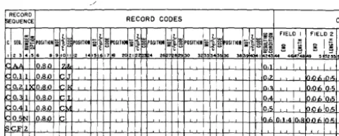
Figure 11 shows the entries necessary in columns 1-43 of the input specifications sheet for the Invoice Report.
In some applications there is more than one kind of record of a given type. For instance, in the invoice example just given, suppose that the file of input data cards contained three kinds of detail cards:
1. a I-punch in column 80, 2. a 2-punch in column 80, 3. a 3-punch in column 80,
For other reports the 1-, 2-, and 3-punches might be significant, but in preparing invoices all three kinds of detail cards should be treated as one type. Therefore, they would receive the same sequence designation. Furthermore, suppose that in the input data file it
were possible that for a given customer there may be any number of detail cards of each kind, including
none of some kinds. Each kind would have N-number within a control group, and each kind would be op-tional within that group. The specifications for the conditions just stated consist of a separate line-entry for each kind of detail card, each having its own re-sulting condition (Figure 12).
When records that are coded differently are to be processed alike for the most part, they have the same sequence designation in columns 2-3 whether that des-ignation is numerical or alphabetic. To represent their unique record codes, however, and to distinguish them later, they receive different resulting-condition num-bers. Such records are said to be in an or relation.
RECORD
~QUENCE
:d
C SEQ. !a..POSITIOIc
, 23 • S 8 • 910 0.5N 0.8.0 0.5N 080 0.5N 08,0
Figure 12.
RECORD CODES
:;t
i~POSITIOI\~
~~
i~
st
ZKI~POSITIOI ~roSITIOI POSITIOI §roSITIOI g5~
- c c '"''C
~!! 1112 1415 Ie 17 10 20 2'~2 • 28 8'29 130 3 3 [3S!6_ 311 b-9ioo
II 0,6
z 07
3 08
Three Kinds of Input Records Defined as One Record-Sequence Type
Control Fields
FIELD I FI
... 1:; .:
~ i ~ ~ . . • 148.
Control fields are record positions containing informa-tion identifying the classificainforma-tions to which the record belongs. Columns 44-73 of the input specifications sheet list the control fields present in each type of input data record. Each field is described by its right-most position in the input record and its length. (For
IBM 1401 Data Processing Systems using 51-column
input data cards, see Special Feature Specificatiof!-S.)
The fields are specified in ascending sequence of con-trol levels beginning with the entries for the most minor level in Field 1 (columns 44-48) and continuing to the right as far as necessary. Six is the maximum number of control fields that can be specified.
It is not necessary that a control field be in the same position in different record-types. It is important, how-ever, that a field be entered under the proper level on the input specifications sheet. None of the heading cards in the invoice example have the lowest level of control, Item Number. Therefore, field 1 is left blank for those record specifications. The next level of con-trol, Customer Number, is present in those records. It
is specified in columns 49-53 of the sheet. The detaii cards in that example have both levels of control. Therefore entries are present for fields 1 and 2 (Figure 13 ).
[image:20.612.302.544.245.316.2]RECORD
r>e:aUENCE RECORD CODES
~
III
J. 1 1 1 1 :::1!: FIELD IC SEQ. i~POSITiOIli:-[~POSIT~q: n ~~SITI~li:~~POgTIOI :;"iI~POSITIONli:-[l1! OSITIOI :;"[l1! ~~ Q
.1j'"
i;1.... (U -Cu " .. " .... l{~ :IE'C,,"," tc:> -i'u~8 ~ §
I 2 '3 .. 56 8 9101112 141516171e 2021 .. 2 7 8 30 '3 33343536 38 9 I 24344 4 148
011 OS,o [J [0,2
021 O,S,o [0, I
0 1 Oa,o 04 !
O~ 1 o SJ) !:::: 05 !
05~ OSJ) k:: I,f, n,1 ,4 In,:
S ;;FZ I
I
Figure 13. Input Specifications for Invoice Report
Sequence Control
CO
FIELD 2 F
l,ol. In,.; 0,06;0,~
0,06In,'i 001. 05 ,110<,10,5
A special entry applies when input data records are present in sequence in a control group of the input data file. The number of the control field governing the sequence of numerically-designated types of records must be specified by the entry SCFx in columns 1-4. The x is the number of the control field. In the invoice example the sequence of records specified relates to customer number. Every change in customer number means that the sequence of records begins again with an Invoice To record. Because customer number is field 2 (Figure 13), the proper entry for this Invoice Report is SCF2 in columns 1-4 on the line below the last record specification. Every application that has sequential-record specifications must have an SCFx entry at the end of the input specifications.
Page Number
Columns 76-77 are used for page numbering. The page-number entry is in the upper right-hand corner of the input specifications sheet. The pages are num-bered consecutively beginning with the spacing chart as page 01.
Card Number
A three-character card number in columns 78-80 estab-lishes the order of entries on the specifications sheet. The first 20 lines of the sheet are prenumbered 010-200. The six unnumbered lines at the bottom of the sheet are for the entry of statements inadvertently omitted and for sheet extension. Insertions can be referenced by numbering the statement with the hun-dreds and tens digit of the statement it is to follow and with anyone of the units digits 1-9. This allows up to nine insertions between two consecutive pre-numbered statements.