2016 International Conference on Electronic Information Technology and Intellectualization (ICEITI 2016) ISBN: 978-1-60595-364-9
Novel Analysis Method for the Solid-liquid
Interface Using Surface Enhanced
Raman Spectroscopy
Bin Jiang
ABSTRACT
It is very important to focus on the solid-liquid interface for analysis of a variety of systems at solid-liquid interface such as electroless deposition processes. In order to avoid the influence of “bulk” solutions, we characterized reductants (i.e., hydrazine, hypophosphite, formaldehyde) adsorption on Ag surface down to the single molecular level by using plasmon antenna enhanced Raman scattering with a high-selectivity component. The concentric-patterned antenna coated with Ag, which consisted of a single hole with coaxial dimples, was designed by Finite Difference Time Domain (FDTD) calculation to enhance the electric field by focusing surface plasmon. By using this antenna and comparing the spectra to the results of Density Functional Theory (DFT) calculations, Raman peaks of adsorbed reductants on Ag were identified. These results suggest that this approach can exactly focus on the solid-liquid interface, and such in-situ characterization will be beneficial for analysis of catalytic reactions, which is one of the most difficult applications in electroless deposition processes.
INTRODUCTION
Precise control of the solid-liquid interface is very necessary in electroless deposition processes or variety of systems at solid-liquid interface. Surface enhanced Raman Scattering (SERS) effect is a breakthrough technique that can strongly
________________________
increase Raman signals from molecules and precisely provide in-situ, ultrasensitive characterization of chemicals on metals down to single molecular level for analysis of solid-liquid interface [1-4]. However, the electromagnetic field depends crucially on the size of the plasmonic metals and the distance from the plasmonic metals in the range of 1-2 nm [5-7]. In generally, SERS approach is difficult to avoid the influence of “bulk” solutions and define the location of the detected molecules, usually affecting the spectral results.
To overcome these problems, this study attempts to demonstrate the characterization of reductants adsorption on Ag surface down to single molecular level using surface enhanced Raman antenna with high-selectivity component. This antenna consists of a single hole with coaxial dimples designed by using FDTD calculation. Such an in-situ characterization approach is required for analysis of a variety of systems at the solid-liquid interface, such as electroless deposition process [8-12]. Meanwhile, the theoretical calculation (DFT) can provide molecular level, basic level information to support and compare with experimental analyses for better understanding the characterizations [13-15].
METHODS
The surface enhanced plasmon antenna was designed as the concentric pattern with coaxial dimples for enhancing the Raman scattering effectively on metal surfaces by using FDTD calculation, whose details are described elsewhere [16]. The structure of the antenna consists of six lines and spaces a pitch of 550 nm and a center dimple with a diameter of 250 nm. The enhanced area was around 50 nm where a localized plasmon was generated according to FDTD calculation. In addition, the surface roughness was within 1 nm in the enhanced area, where could enhance the Raman scattering at right angle. Therefore, we changed the focus of measurement precisely by using a piezometer stage, which could allow us to take measurement at varying distances from the antenna. The electric field of the antenna was calculated with FDTD solver (Fullwave) provided by RSoft Design Group.
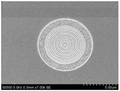
The concentric pattern of plasmon antenna was formed on a Si substrate by using UV-nanoimprint lithography (Kyodo-international). The Ag (23) layer with 100 nm thickness was then sputter deposited on the concentric pattern. The SEM image of Ag plasmon antenna was shown in Figure 1 (FE-SEM, S-4800, Hitachi).
an objective lens at a magnification of 100 × with NA (0.9). The data acquisition time was 1.0 s. The wavenumber resolution was 2.4 cm-1 when the grating (600 grooves/mm) was used, and the wavenumber range was 50 cm-1 - 4000 cm-1. The laser power irradiated on the sample surface was 3 mW. Bath temperature and pH were 50 oC and 8.6.
The DFT calculations were performed using the B3LYP functional as implemented in the Gaussian 03 package [17], which was a combination of Becke’s three-parameter hybrid exchange functional (B3) [18] and the Lee-Yang-Parr correlation functional (LYP) [19]. The Gaussian Basis sets were P, C, H/6-31G** [20] and O, N/6-31 +G** [21]. The solvation effect was taken into account by the
[image:3.612.202.394.277.423.2]self-consistent reaction field method with an isodensity surface polarized continuum model (SCRF-IPCM) [22], which used dielectric constant 80.0 [-].
Figure 1. SEM image of Ag plasmon antenna.
TABLE I. EXPERIMENTAL CONDITIONS OF REDUCTANTS (NOT IN CONTACT WITH PLASMON ANTENNA).
TABLE II. EXPERIMENTAL CONDITIONS OF REDUCTANTS (PLACED ON PLASMON ANTENNA).
Chemicals Concentration (M)(a) (b) (c)
H2NNH2·H2O
NaH2PO2·H2O
5 - - - 5 - HCHO - - 5
Chemicals Concentration (mM)(a) (b) (c)
H2NNH2·H2O
NaH2PO2·H2O
[image:3.612.144.454.617.684.2]RESULTS AND DISCUSSION
Table III and Figure 2 show the theoretical Raman spectrum calculated by using DFT and experimental Raman spectra of the “bulk” solutions in high concentration (not in contact with the plasmon antenna). A Raman spectrum of reductants was given as Fig. 2. Corresponding to the theoretical Raman spectrum of reductants in Table III, all characteristic peaks of reductants were observed as follows:
1. Figure 2 (Solid line (a)) shows the Raman spectrum of N2H4, which has six pronounced, polarized lines at 469, 818/924, 1132, 1303/1366, 1633 (overlapping Raman band), and 3293 (3213, 3356) cm-1. We assign these lines to the NH2 torsional (vertical), NH2 bending (out of plane), NN stretching, NH2 torsional (horizontal), NH2 bending (in plane), and NH stretching, respectively, by comparing them with the theoretical Raman spectrum of hydrazine and other studies [23, 24].
2. Figure 2 (Dash line (b)) shows the Raman spectrum of NaH2PO2, which has six pronounced, polarized lines at 466, 816, 921, 1060/1197, 1136 (overlapping Raman band), and 2315 cm-1 (overlapping Raman band). These lines are assigned to the OPO bending (in plane), HPH torsional (vertical), HPH torsional (horizontal), PO stretching, HPH bending (out of plane) or HPH bending (in plane), and PH stretching, respectively, by comparing them with the theoretical Raman spectrum of hypophosphite and other studies [25, 26].
3. Figure 2 (Dot line (c)) shows the Raman spectrum of HCHO, which has eight pronounced, polarized lines at 458, 776/1386, 1018, 1122, 1296, 1426, 1545, and 2404 cm-1(overlapping Raman band). We also have assigned these lines to the OCO bending, CO stretching, COH bending, CH2 torsional (horizontal), CH2 torsional (vertical), HCH bending (out of plane), HCH bending (in plane), and CH stretching, respectively, by comparing them with the theoretical Raman spectrum of formaldehyde and other studies [27, 28].
Figure 2. Raman spectra of reductant solutions.
TABLE III. THE DFT CALCULATION OF REDUCTANTS.
Vibrational mode Wavenumber (cm-1)
NH2 torsional(vertical) 467.3
NH2 bending(out of plane) 798.1,953.1
NN stretching 1119.2 NH2 torsional(horizontal) 1292.6,1321.9
NH2 bending (in plane) 1680.9,1698.7
NH stretching 3469.0,3475.8,3585.7,3590.4 OPO bending (in plane) 437.8
HPHtorsional(vertical) 795.2 HPHtorsional(horizontal) 920.1
PO stretching 1023.3,1218.2 HPH bending(out of plane) 1112.4
HPH bending(in plane) 1176.8 PH stretching 2236.3,2176.6 COH bending 76.8,1068.1 OCO bending 424.8 CO stretching 664.5,1362.1 CH2 torsional (horizontal) 1097.4
CH2 torsional (vertical) 1233.3
HCH bending(out of plane) 1388.2 HCH bending(in plane) 1536.7
[image:5.612.142.453.363.677.2]The structure of the antenna was designed for efficiently enhancing Raman scattering on Ag by FDTD calculation. The SERS effect of deposited Ag is much higher than other metals, whose details are described elsewhere [16]. Figure 3 shows the experimental Raman spectra of the reductants in low concentration on the Ag antenna. There was no Raman shift in the Raman spectrum of the reductants solution in low concentration alone. In the Fig. 3, Raman spectra of adsorbed hydrazine on Ag (a); adsorbed hypophosphite on Ag (b); adsorbed formaldehyde on Ag (c); and only Ag antenna (d) were given. By comparing with the Raman spectra of only reductant solutions (not in contact with the antenna), extra Raman shifts at 360 cm-1 were observed in the figure. Because these Raman peaks were observed
only after the reductants were dropped on the Ag antenna, while there were no these peaks in the Raman spectra of only reductant solutions. Therefore, we defined this wavenumber domain as Ag-reductants bonding. Moreover, there were other lines of undetermined scattered radiation which we had assigned tentatively to the characteristic peaks of reductants.
[image:6.612.201.412.360.584.2]From these results, the surface enhanced Raman antenna could dramatically enhance the Raman signals and precisely characterize the adsorption of reductants on metal surfaces.
CONCLUSIONS
In this work, an approach for focusing on the solid-liquid interface to analyze the characterization of reductants adsorption on metal surfaces using surface enhanced Raman antenna was proposed. By using the antenna and comparison with DFT results, Raman peaks of adsorbed reductants on Ag were provided, defining as Ag-reductants bond. From the experimental and calculated analyses, we demonstrated that this method had a possibility to define the place and structure of adsorbed reductants just only on the plasmon antenna. In a word, such in-situ characterization approach focusing on the solid-liquid interface is important for analysis of various systems at solid-liquid interface; this will be very helpful for understanding and establishing novel and highly controlled electroless deposition processes.
ACKNOWLEDGMENTS
This work was carried out at the ‘‘Northwest university research fund (Grant No. 338020015)’’ under Northwest university, and was financially supported in part by Scientific research plan projects of Shaanxi education department (Grant No. 203010019).
REFERENCES
1. Campion A., Kambhampati P., 1998, Surface-enhanced Raman scattering. Chem Soc Rev, 27: 241-250.
2. Moskovits M., 2005, Surface-enhanced Raman spectroscopy: a brief retrospective. J Raman Spectrosc, 36: 485-496.
3. Bin J., Masahiro K., Masahiro Y., Takayuki H., 2013, Effect of Thiourea on Oxidation of Hypophosphite Ions on Ni Surface Investigated by Raman Spectroscopy and DFT Calculation. Journal of The Electrochemical Society, 9: D366-D371.
4. Stewart M.E., Anderton C.R., Thompson L.B., Maria J., Gray S.K., Rogers J.A., Nuzzo R.G., 2008, Nanostructured Plasmonic Sensors. Chem Rev, 108: 494-528.
5. Tian Z.Q., Ren B., Wu D.Y., 2002, Surface-Enhanced Raman Scattering: Form Noble to Transition Metals and from Rough Surfaces to Ordered Nanostructures. J Phys Chem, 106: 9464-9483.
6. Jiang J., Bosnick K., Maillard M., Brus L., 2003, Single molecule Raman spectroscopy at the junctions of large Ag nanocrystals. J Phys Chem B, 107: 9964-9972.
7. Talley C.E., Jackson J.B., Oubre C., Grady N.K., Hollars C.W., Lane S.M., Huser T.R., Nordlander R., Halas N.J., 2005, Surface-Enhanced Raman Scattering from Individual Au Nanoparticles and Nanoparticle Dimer Substrates. Nano Lett, 5: 1569-1574.
8. Shimada T., Tamaki A., Nakai H., Homma T., 2007, Molecular Orbital Study on the Oxidation Mechanism of Hydrazine and Hydroxylamine as Reducing Agents for Electroless Deposition Process. Electrochemistry, 75(1): 45-49.
9. Ouchi T., Arikawa T., Shimano N., Homma T., 2011, CoNiP Electroless Deposition Process for Fabricating Ferromagnetic Nano dot Arrays. Electrochim Acta, 56: 9575-9580.
11. Anik T., Touhami M.E., Himm K., Schireen S., Belkhmima R.A., Abouchane M., Cisse M., 2012, Influence of pH Solution on Electroless Copper Plating Using Sodium Hypophosphite as Reducing Agent. Int J. Electrochem Sci, 7:2009.
12. Bin J., Siggi W., Masahiro K., Masahiro Y., Takayuki H., 2013, Raman and DFT Study of the Reaction of Hydrazine and Hypophosphite on a Cu Surface in the Electroless Deposition Process. Electrochemistry, 9: 1-4.
13. Kunimoto M., Shimada T., Odagiri S., Nakai H., Homma T., 2011, Density Functional Theory Analysis of Reaction Mechanism of Hypophosphite Ions on Metal Surfaces. J Electrochem Soc, 158: D585-D589.
14. Öhrström L., 2005, Can DFT calculations help the molecular designer to construct molecule based magnetic materials?. Comptes Rendus Chimie, 8: 9-10.
15. Homma T., Nakai H., Onishi M., Osaka T., 1999, Ab initio molecular orbital study on the oxidation mechanism for dimethylamine borane as a reductant for an electroless deposition process. J Phys Chem B, 103(10):.1774-1778.
16. Yanagisawa M., Shimamoto N., Nakanishi T., Saito M., Osaka T., 2008, Organic Molecular Sensor with Plasmon Antenna. ECS Trans, 16(11): 397-409.
17. Frisch M.J., Trucks G.W., Schlegel H.B., Scuseria G.E., Robb M.A., Cheeseman J.R., Montgomery J.A.,Vreven J.T., Kudin K.N., Burant J.C., Millam J.M., Iyengar S.S., Tomasi J., Barone V., Mennucci B., Cossi M., Scalmani G., Rega N., Petersson G.A. Nakatsuji H., Hada M., Ehara M., Toyota K., Fukuda R., Hasegawa J., Ishida M., Nakajima T., Honda Y., Kitao O., Nakai H., Klene M., Li Z., Knox J.E., Hratchian H.P., Cross J.B., Bakken V., Adamo C., Jaramillo J., Gomperts R., Stratmann R.E., Yazyev O., Austin A.J., Cammi R., Pomelli C., Ochterski J.W., Ayala P.Y., Morokuma K., Voth G.A., Salvador P., Dannenberg J.J., Zakrzewski V.G., Dapprich S., Daniels A.D., Strain M.C., Farkas O., Malick D.K., Rabuck A.D., Raghavachari K., Foresman J.B, Ortiz J.V., Cui Q., Baboul AG, Clifford S., Cioslowski .J, Stefanov BB, Liu G., Liashenko A., Piskorz P., Komaromi I., Martin R.L., Fox D.J., Keith T., Al-Laham M.A., Peng C.Y., Nanayakkara A., Challacombe M., Gill P.M.W., Johnson B., Chen W., Wong W.M., Gonzalez C, Pople JA, 2004, Gaussian 03. Revision C 02 Gaussian Inc Wallingford CT.
18. Becke A.D., 1993, A new mixing of Hartree-Fock and local density-functional theories. J Chem Phys, 98(2): 1372-1377.
19. Lee C., Yang W., Parr R.G., 1988, Development of the Colle-Salvetti correlation-energy formula into a functional of the electron density. Phys Rev B, 37: 785.
20. Woon D.E., Dunning T.H.Jr., 1993, Gaussian Basis Sets for Use in Correlated Molecular Calculations. III. The Atoms Aluminum Through Argon. J Chem Phys, 98: 1358-1371.
21. Clark T., Chandrasekhar J., Spitznagel G.W., Schleyer P.V.R., 1983, Efficient Diffuse Function- Augmented Basis Sets for Anion Calculations. III The 3-21 + G Basis Set for First-Row Elements. J Comput Chem, 4: 294-301.
22. Hay P.J., Wadt W.R., 1985, Ab initio effective core potentials for molecular calculations. Potentials for K to Au including the outermost core orbitals. J Chem Phys, 82:.299.
23. Durig J.R., Griffin M.G., Macnamee R.W., 1975, Raman spectra of gases (XV: Hydrazine and Hydrazine-d4). J Raman Spectrosc, 3: 133-141.
24. Personette W., Szczepanski J., Kubulat K., Vala M., 1989, Raman spectroscopic study of chain complexes of bis (hydrazine) zine and manganese halides. J Raman Spectrosc, 3: 147-153. 25. Tsuboi M., 1957, Infrared spectrum and crystal structure of cellulose. J Am Chem Soc, 79: 1351. 26. Liu R, Moody P.R., Vanburen AS, Clark J.A., Krauser J.A., Tate D.R., 1996, On assignment of
fundamental vibrational modes of hypophosphite anion and its deuterated analogue. Vib Spectrosc, 10: 325-329.
27. Hanoune B., Paccou L., Delcroix P., Guinet Y., 2011, Raman identification of H2CO in aqueous solutions. J Raman spectrosc, 42: 1202-1204.