© 2017, IRJET | Impact Factor value: 5.181 | ISO 9001:2008 Certified Journal | Page 1293
paper design of PM motor is carried out for this rating and finite element analysis is done for design validation by two approach using motor solve. It is very difficult to make different lamination for each different rating of motor. It will increase cost of motor and also it requires time. In this paper
induction motor lamination is used for design of PM motor.
1. INTRODUCTION
In this paper PM motor for elevator application is designed by two approaches. In first approach rating of PM motor is calculated using below Torque and speed equation. And based on PM motor design calculation PM motor is design. So in this approach one have to manufacture special lamination for PM motor. This will increase money and time consumption.
So to reduce money and time consumption one can design PM motor by fixing Main dimension like Stator outer Diameter and rotor outer diameter according to number of slot and available stator stamping in market. Here interesting things is that we can use induction motor stamping. By fixing above parameter and changing length and aspect ratio one can design PM motor which has same specification like same torque, speed, output power, efficiency and flux density etc.
Hence in second approach after taking rating of PM motor One can directly design PM motor by fixing Stator outer Diameter and rotor outer diameter according to number of slot and available stator stamping in market. Only one condition should be satisfied that is ratio of length and aspect ratio must match with stator outer diameter.
1.1
Requirements of elevator systems
The major requirements in the motor design of gearless elevator systems are torque and speed. These two parameters can be calculated by operating speed, cabin weight capacity, type of suspension and pulley diameter of designed elevator system
For some given elevator specifications such as 680 kg (For 10 people) weight capacity, 1.5 m/s cabin velocity, 2: 1
Tmotor = [rpulley x g x (Mcarry) x η / μ]]
Where,
Rpulley:
The radius of drive pulley (m) (0.12 m), g: The force of gravity (m/s2) (9.88 m/s2)
Mcarry:
Maximum carrying capacity (kg) (680 kg) μ: The coefficient for suspension type. I for direct
Suspension, 2 for 2: 1 suspension. Design was carried out for μ =2.
η: Well and rope system efficiency (70%) Tmotor = [0.12 x 9.88x(680) x (0.7)/2 ] Tmotor = 279.88 N.m
Motor rated speed;
ω = μ x (v / rpulley) (rad/ s)
v: cabin vertical velocity = 1.5 m/s
ω = 2 x (1.5/ 0.12) = 25 (rad/s)
n = ω x (60/2 x π) (rpm)
n = 25 x (60/2 x π) = 238.8 (rpm)
Rated power;
Pmotor = T. ω
Pmotor = 279.88 x 25 = 7000 W
1.2
Simple design of PM motor
© 2017, IRJET | Impact Factor value: 5.181 | ISO 9001:2008 Certified Journal | Page 1294
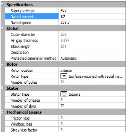
Fig -1: motor solve model of 7 kW motorFig -2: General input of 7 kW motor
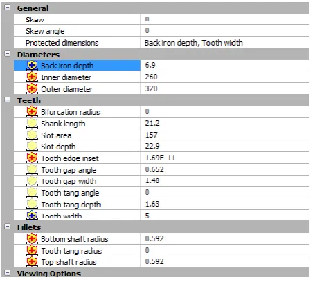
Fig -3: stator input of 7 kW motor
[image:2.595.43.564.41.794.2]Fig -4: Rotor input of 7 kW motor
Fig -5: Material
[image:2.595.296.559.60.301.2] [image:2.595.50.275.267.477.2] [image:2.595.318.550.339.536.2] [image:2.595.49.277.508.712.2]© 2017, IRJET | Impact Factor value: 5.181 | ISO 9001:2008 Certified Journal | Page 1295
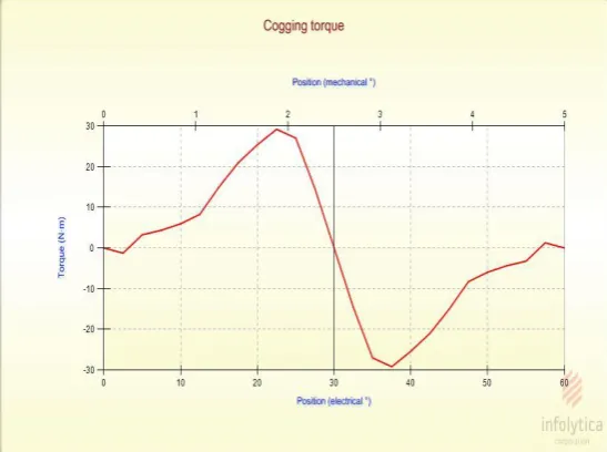
Fig -7: torque profile [image:3.595.39.554.77.692.2]Fig -8: cogging torque
Fig -9: Result of motor solve
2. Design of PM motor by second approach
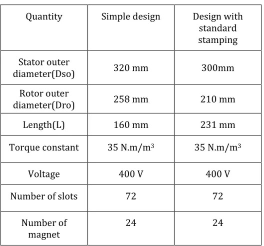
We have taken the standard stamping for 7 kW motor Stator Outer Diameter Dso = 300 mm
Rotor Outer Diameter Dro = 210 mm Number of slot = 72
Rotor outer
diameter(Dro) 258 mm 210 mm
Length(L) 160 mm 231 mm
Aspect ratio 0.5 0.77
[image:3.595.327.541.410.633.2]So from above table it is clear that one can design same rating motor by changing length and aspect ratio and all other parameter is same in both cases.
© 2017, IRJET | Impact Factor value: 5.181 | ISO 9001:2008 Certified Journal | Page 1296
Fig -11: stator input of 7 KW motor with standard [image:4.595.38.567.45.765.2]Stamping
Fig -12: Rotor input of 7 KW motor with standard stamping
[image:4.595.301.560.59.312.2]Fig -13: flux density with standard stamping
Fig -14: torque profile with standard stamping
[image:4.595.54.269.337.519.2]Fig -15: cogging torque with standard stamping
[image:4.595.310.584.356.560.2]© 2017, IRJET | Impact Factor value: 5.181 | ISO 9001:2008 Certified Journal | Page 1297
diameter(Dro)
Length(L) 160 mm 231 mm
Torque constant 35 N.m/m3 35 N.m/m3
Voltage 400 V 400 V
Number of slots 72 72
Number of
magnet 24 24
[image:5.595.30.295.144.390.2]From above table it is clear that there is huge difference between sizes of two motor but in result, both motor gives same output in terms of torque and power.
Table -3: comparison of motor solve result
Quantity Simple design Design with
standard stamping
Torque 282 N.m 281 N.m
Output power 7.06 kW 7.03 kW
Efficiency 94.6 94.8
Flux desity in
stator yoke 1.45 T 1.4 T
Flux desity in
stator teeth 1.66 T 1.64 T
Flux desity in
rotor yoke 1.46 T 1.43 T
From above table it is clear that result of both approaches is very nearer to each other. So one can use second approach and design motor for any rating.
rating of permanent magnet motor. We only need to make length as variable.
REFERENCES
[1] D. C. Hanselman," Brushless Permanent Magnet Motor Design", New York: McGrawHill, 1994.
[2] “Design of Brushless Permenent Magnet
Machine”,J.Hendershot,T.J.E Miller , Motor Design Book ,secound edition , 2010.
[3] "Comparative Design of Direct Drive PM Synchronous Motors in Gearless Elevator Systems ",Hicret Yetis, Hande Boztepeli, YusufYasa, Istanbul, Turkey, October 2-4,2013
[4] “Application of Permanent magnet Excited synchronous motor and direct drive elevator system”,( In Turkish) ,H.T.Duru, R.Demiroz, Y.Toktas,izmir 2006.
[5] "A New Configuration of Drive System for High Speed Gearless Elevator",Dae- Woong Chung, Hyung-Min Ryu, [6] "Increasing Energy Efficiency in Elevator Systems by Direct Drive and Permanent Magnet Synchronous Machines" (In Turkish), H.T.Duru, RDemiroz, Y.Toktas, I. EVK Sempozyumu, Kocaeli 2005.
BIOGRAPHIES
Harsh .R Goswami is final year student in electrical department in Nirma university, Ahmedabad
[image:5.595.32.327.466.704.2]