A Variable Frequency Angle-Based Repetitive Control for Torque
Ripple Reduction in PMSMs
M.Tang*, A.Gaeta
†, A.Formentini*,P.Zanchetta*
* The University of Nottingham, University Park, Nottingham, UK, [email protected] † reDrives s.r.l., via Tommaso Fazello 5, Lentini (SR), Italy, [email protected]
Keywords: deadbeat control, repetitive control, PMSM, torque ripple, variable frequency
Abstract
This paper presents a novel method for torque ripple reduction in PMSM drives at variable speed, using a combination of angle-based repetitive control and deadbeat current control. Based on the internal model principle, repetitive control is capable to reduce periodic torque ripple by generating a compensating action that consequently need to be synchronized with the original ripple. The time to angle, angle to time conversions for repetitive control, which improve both the stability and the performance when the sampling frequency is not integer multiple of the speed, are presented. A transient detection strategy is also developed to allow a stable torque ripple reduction even during speed and load changes.
1 Introduction
Torque ripple reduction in permanent magnet synchronous machines (PMSMs) has been studied for decades. Using traditional vector control, since the output torque of the machine can be expressed as a function of current, many of the existing torque ripple suppression methods reduce torque ripple by introducing a tailored compensating periodic current ripple [1-5]. In some cases, current references are generated by lookup tables computed from measurements [6]. In any case the bandwidth of the current loop should be high enough to track such current references, which may contain high frequency components.
Besides, since torque ripple is mainly periodic [7], repetitive control (RC) can be a very powerful solution for periodic torque ripple reduction or periodic current references tracking, depending on where the repetitive controller is located. For example, repetitive control can work in conjunction with normal PI controllers in current loops to remove errors between periodic current references and current feedback [8]. Alternatively, the repetitive control can be placed in the speed loop where the controller can use the speed error [9-10] or the torque error [7,11] as an input producing periodic current references. Among these two methods, the latter one may be preferred to avoid computing current lookup tables. It is also to be noted that the values of periodic current references relate not only to the rotor position, but also to the level of saturation and parameter variations of the machine. It is therefore difficult, time and resource consuming to derive the
right lookup tables for the different expected working conditions.
Repetitive control has been applied successfully for torque ripple reduction in some existing works in scientific literature [7, 9-11]. RC is effective on reducing any periodic torque ripple without necessarily knowing the machine parameters, no matter the ripple is caused by cogging torque, inverter nonlinearities [12], flux harmonics, current offset, current scaling error, or mechanical unbalance.
However, the knowledge of the frequency of torque ripple is necessary for a time-domain RC to maximize disturbance rejection. The time-domain RC would need to realign its memory length to the new period of the repetitive torque ripple each time the speed is changed. For this reason, the memory content should be reset and a new learning process should be started since the phase of the periodic disturbance is not maintained among speed changes.
Considering that PMSMs are very often used as variable speed drives and the torque ripple is in fact periodic with respect to rotor position, [10] presents an angle-based RC which works effectively within a limited variable speed range of 50 rpm to 70 rpm.
In the angle domain, the frequency of the previously described torque disturbance is fixed and the controller memory does not need to be resized when the speed is changed; the phase of torque disturbance due to cogging torque and flux harmonics within a full electrical rotation are marginally affected by the speed and by saturation conditions. Therefore the RC should learn only the amplitude variation of the torque disturbance as a consequence of a speed/load change and parameter variations.
The latter consideration can be extended to torque disturbances due inverter non-linearities, current offset or scaling error if the current angle is kept constant as usually happens in case of surface PMSMs when controlled at zero direct current to minimise losses.
However, none of these papers considered that conventional PI current control may need to be replaced by other high bandwidth current control where torque ripple reduction is demanded at high speed. Besides, the interaction between the speed loop PI controller and the repetitive controller should be considered for better performance. Also torque ripple reduction has been proved effective only for a reduced range of low speed.
largely variable speed, arising from the use of the speed feedback loop for torque ripple compensation, have never been addressed in any scientific work, according to authors’ knowledge.
This paper proposes a novel combination of angle-based repetitive control and deadbeat current control (DBCC) [13] for torque ripple reduction in PMSMs, aimed for variable speed/load applications. Simulation tests have shown that this strategy significantly improves the synchronization of the generated RC compensation action at variable frequency, widely expands the frequency range of the torque ripple suppression, and improves performance not only at steady state, but also during transients. Therefore, high performance of the drive system can possibly be achieved without the extra cost for improving the manufacturing process, and even with worn shafts or unbalanced loads.
This paper is organised as follows. System models equations and diagrams of the proposed control are explained in detail in section 2. Simulation results are shown in section 3. The results and advantages of the proposed control are discussed in section 4. Finally, conclusions with discussion over the improvements introduced by the proposed approach are given in section 5.
2 Model and equations
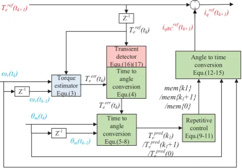
[image:2.595.310.548.80.178.2]The overall structure of the proposed system is depicted in figure 1, where the details of the proposed repetitive control are shown in figure 2. For a surface mounted PMSM, the output torque is considered proportional to only the q-axis current, while the d-axis current is set to zero.
PI +
- ++
Angle- based repetitive controller
Deadbeat
controller abcdq/ inverter PMSM
abc/dq ¹rref
iqref
vdqref vabcref
iabc
¹r
ϑm
GcCL(z) Gsp(z)
idq Transient
detector
Torque estimator
Teref
idref=0
iqRCref
Figure 1: Block diagram for the proposed angle-based repetitive control and deadbeat current control
Transient detector Equ.(16)(17)
Torque estimator Equ.(3)
ωr(tk) Time to
angle conversion
Equ.(4)
Teest(tk)
Teerr(tk)
Time to angle conversion
Equ.(5-8) Te
pred(k 1)
/Tepred(k1+1)
/Tepred(0)
Repetitive control Equ.(9-11)
mem{k1} /mem{k1+1}
/mem{0}
Angle to time conversion Equ.(12-15)
iqRCref(tk+1)
+ +
Teref(tk+1) i
qref(tk+1)
Z-1
Teref(tk)
Z-1
ωr(tk-1)
θm(tk)
Z-1
θm(tk-1)
(a) Angle-based repetitive control in the control system
Tepred(k1)
/Tepred(k1+1)
/Tepred(0)
GRC
mem{k1} /mem{k1+1}
/mem{0}
+ +
Delay of a full circle rotation
memprev{k1}
/memprev{k 1+1}
/memprev{0}
QRC
[image:2.595.45.291.448.554.2](b) Repetitive control (Equation (9-11)) Figure 2: Diagram of the angle-based repetitive control
2.1 Deadbeat current control loop
The deadbeat current control loop has been implemented as described in [6,13]. In closed loop it can be expressed by a delay of two sampling periods as in Equation (1) when operating within the voltage limitation determined by the inverter DC bus voltage.
2
GcCL(z) z (1)
2.2 Torque estimator
The discretized mechanical plant of the motor is described in Equation (2):
ssp
s r
e l
T G (z)
Jz J BT
(z) T (z) T
Z
(2) Where, Ts is the sampling period, J is the motor and load
inertia, B is friction factor, and Tl is the load torque.
The RC is connected with the speed loop PI using a “plug-in” structure. Assuming the pre-knowledge of the mechanical parameters (inertia Jest and friction factor Best), the output
torque is estimated and then used as an input for the RC. The output torque is estimated based on the reverse of Equation (2) as follow:
est
est r k r k 1 est
e r
s
ref e
k k k
J [ ( ) ( )]
T ( ) t t B ( ) T
T (
t Z Z Z t t ) (3)
Where, Teest(tk) is the estimated output torque at tk, used as
input for RC at tk+1,¹r(tk) is the rotor angular speed at tk; ¹r(tk-1)is the rotor angular speed at tk-1; the load torque is
approximated using the value of the torque reference at tk, Teref(tk).
2.3 Time to angle conversion
Together with the estimated torque at tk, Teest(tk), the torque
reference Teref(tk) generated by the speed loop PI controller at tk, and the rotor mechanical position at tk, θm(tk), are all
inputted to the repetitive controller at tk+1 which means at the
beginning of the (k+1)th sampling period.
The torque error Teerr at tk is first calculated as in Equation (4):
err ref est
e k e k e k
[image:2.595.52.292.594.760.2]array mem are updated by the torque errors at only N chosen rotor angles out of the whole mechanical resolution of 2πand indicate the q-axis currents required for torque ripple reductions at the N chosen rotor locations. For example,
mem{i}, the (i+1)thvalue in the array mem,(i is within [0,N-1]), is the q-axis current iqRC required for reducing torque
error when the rotor mechanical position is exactly i*2π/N. The rotor location index k1 is defined as in Equation (5):
m k
1 1
N (t )
k floor , k [0, N 1]
2 T
§ ·
¨ S ¸
© ¹ (5)
Where, the value of N is chosen to be around the ratio between the sampling frequency fsand the rated speed ωr of
the machine in Hz.
Since the rotor position cannot always be measured exactly at points coincident with integers multiple of 2π/N, interpolations are necessarily used to predict the torque error at the closest chosen rotor locations (θm=0, 2π/N,4π/N,…, 2π).
Linear interpolations are executed as in Equations (6)(7)(8) only if the value of k1 is different from the one obtained at the
previous sampling period. In the case of positive rotation:
pred
e 1
err err
err e k e k 1
e k 1 m 1 m k 1
m k m k 1
T (k )
T (t ) T (t )
T (t ) [ (k ) (t )]
(t ) (t )
T T
T T
(6)
In the case of negative rotation and k1Į(N-1):
pred err
e 1 e k 1
err err
e k e k 1
m 1 m k 1
m k m k 1
T (k 1) T (t ) T (t ) T (t )
[ (k ) 2 / N (t )] (t ) (t )
T S T
T T
(7)
In the case of negative rotation and k1=(N-1):
pred err
e e k 1
err err
e k e k 1
m 1 m k 1
m k m k 1
T (0) T (t ) T (t ) T (t )
[ (k ) 2 / N (t )] (t ) (t )
T S T
T T
(8)
Where, Tepred(k1) is the torque error if the rotor mechanical
angular position equals to θm(k1)=k1(2π)/N, Teerr(tk) and Teerr(tk-1) are the torque errors at tkand tk-1,θm(tk) and θm(tk-1)
are the rotor mechanical angular position at tkand tk-1. When
the direction of the rotor movement is opposite to the positive direction of the encoder, thus negative rotation, Tepred(k1+1) is
calculated instead of Tepred(k1). This is because the
interpolation is more accurate estimating the torque error at θm(k1+1)=2π(k1+1)/N, which is in between the current
position θm(tk) and the position at the previous period θm(tk-1),
than estimating the torque error at θm(k1)=k1(2π)/N, which has
not been reached.
2.4 Repetitive control
After converting the torque error at the time tk into the torque
error at position θm(k1) or θm(k1+1) or θm(0), the memory
array can now be updated according to the repetitive control
Equations (9)(10)(11) (Figure 2(b)). Again, only when the rotor location index k1 is different from the one at the
previous sampling period, the memory array would need to be updated.
For positive rotation:
prev pred
1 1 RC e 1 RC
mem{k } mem {k } Q T (k ) G (9) For negative rotation and k1Į(N-1):
prev pred
1 1 RC e 1 RC
mem{k 1} mem {k 1} Q T (k 1) G (10) For negative rotation and k1=(N-1):
prev pred
RC e RC
mem{0} mem {0} Q T (0) G (11) Where, QRC is the forgetting factor of RC, GRC is the gain of
RC, mem{k1} is the (k1+1)thvalue in the memory array mem,
which indicates q-axis current required for compensating the torque ripple at rotor position k1*2π/N, memprev{k1} is the
previous value of mem{k1} obtained at the time of one full
circle rotation ago.
2.5 Angle to time conversion
As shown in figure 2(a), the output of the repetitive controller after the angle to time conversion acts as an additional q-axis current reference, iqRCref. Because of the delay of the current
loop (2Ts), the current reference outputted at tk+1, iqRCref(tk+1),
will be achieved at tk+3. The future rotor position at tk+3 is
predicted and converted to be within [0, 2π] as in Equation (12):
^
`
fut
m(tk 3 ) mod m(t )k r(t ) *3T , 2k s
T ª¬ T Z Sº¼ (12)
A Future rotor location index k2 is defined as in Equation (13): fut
m k 3
2 2
N (t )
k floor , k [0, N 1]
2
§ T ·
¨ S ¸
© ¹ (13)
To compensate the overall delay of 3Ts (2Ts for the current
loop and 1Ts for processing time), the q-axis current reference
generated by RC at tk+1, iqRCref(tk+1), should be chosen from
the memory array according to the future rotor mechanical position at tk+3, θm(tk+3). Again, linear interpolations are used
for estimating the value between mem{k2} and mem{k2+1}, as
in Equations (14)(15): When k2Į(N-1):
2
2 2 fut 2
m k 3 ref
qRC k 1 mem{k }
N mem{k 1} mem{k } k 2
(t )
2 N
i t
ª Sº
T« »
S ¬ ¼
(14)
When k2=(N-1):
ref
qRC k 1 2
2 fut 2
m k 3
mem{k } N mem{0} mem
i t
{k } k 2
(t )
2 N
ª Sº
T« »
S ¬ ¼
(15)
The angle-based RC allows maintaining torque ripple compensation even during speed and load changes. In fact the learning process, after a transient, only needs to be updated with the small amplitude changes in the torque ripple due to the changed conditions (saturation of the machine for example) since the frequency and phase of the torque ripple are fixed with rotor position. However the learning process has to be temporarily disabled during each transient, to avoid the RC may output an excessive compensating reference current as a consequence of the non-existent large torque ripple estimated during each sudden change in speed. Therefore, a transient detection routine is designed to detect speed/load changes and disable the learning process accordingly.
In details, a speed transient will be detected once the change of the torque reference Teref generated by the speed loop PI
controller, ΔTeref, is greater than a chosen threshold ΔTe sudden-max as in Equation (16):
Once ref ref ref sudden max
e k e k e k 1 e
T (t ) T (t ) T (t ) T
ª º!
¬ ¼
ref ref ref sudden max
e k e k e k 1 e
T (t )ref T (t ) T (t ) T
e kk ª ee kk ee k 1k 1 º e
ref ref
ref re
ref ref
ref re
ref re
¬ eeeeeeeee kkkkkkkkkk eee k 1k 1k 1k 1k 1 ¼
ref ref
ref re
ref re
ref re
ref re
T (t ) T (trefrefrefrefref refrererere )
e k e k 1
e k k 1
e k
e k
e k :
ref
e k
T (t ) 0 (16) In addition, a load changes will be detected if the sum of ΔTeref, ΔTesum is larger than a chosen threshold ΔTesum-max as in
Equation (17):
Once sum sum ref sum max
e k e k 1 e k e
T (t ) T (t ) T (t ) T
ª º!
¬ ¼
sum sum ref sum max
e k e k e
Tsum(t ) Tsumsum(t ) T (t )refref T
e kk ª ee k 1k 1 ee kk º e
sum ref
sum ref
¬ eeeeeeeee kkk 1kkk 1k 1kkk eeeee kkkkk ¼
sum ref
T (t ) T (t ) T (t ) T (t ) Tsumsumsumsumsum(t ) T (t )refrererere
e k 1 e k
e k e k
e k
e k
e k :
ref
e k
T (t ) 0 (17) In both speed and load changes, the torque error Teerr as
defined in 2.3 is set to zero to block the learning procedure.
3 Simulation results
A PMSM model has been built in MATLAB/Simulink for simulating the effectiveness of the proposed method. It is worth noting that, in order to accurately simulate the non-sinusoidal flux distribution and cogging torque of PMSM in Simulink, two lookup tables, derived from a finite element (FE) model of the same motor, are used for the magnetic flux, and for the cogging torque. Parameters for RC are as Table 1:
Rated speed of motorωr 3000rpm=50Hz
Length of memory array N 300=15k/50 Sampling frequency fs 15kHz
Sampling period Ts 66.7μs
Gain of RC GRC 0.3
Forgetting factor of RC QRC 0.999
Threshold for detecting speed changes ΔTesudden-max
0.3Nm
Threshold for detecting load changes ΔTesum-max
[image:4.595.341.503.153.237.2]0.3Nm
Table 1: Parameters of RC in simulation
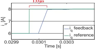
Figure 3 shows a successful implementation of the deadbeat current control. The speed of the motor is kept at 100rpm and the q-axis current reference iqref steps from 6A to 8A, the real
q-axis current reaches the reference after 133μs (=2Ts) as
designed.
0.0299 0.0301 0.0303 6
7 8
Time [s]
i q
[A
]
i
q feedback
i
q reference 133μs
Figure 3 Performance of deadbeat current control
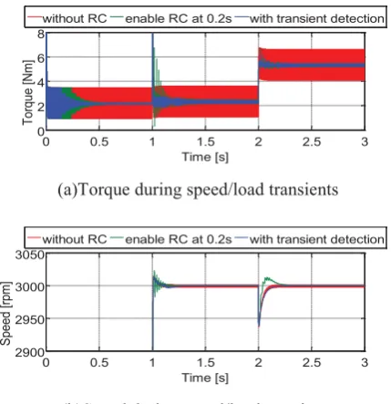
The resulting torque and speed waveforms with and without interpolation in the time to angle conversion are shown in Figure 4, where a speed change from 0 to 2995rpm (=49.917Hz) is applied at 0s and the load torque is set to be 5Nm. The speed 2995rpm is chosen since the sampling frequency 15kHz is then not integer multiple (300.5) of the speed. The torque and speed waveforms with and without the proposed transient detection strategy under speed/load changes are shown in Figure.5, where a speed change from 1500 to 3000rpm is applied at 1s and a load change from 2Nm to 5Nm is applied at 2s.
4 Discussion
Generally, the effectiveness of RC depends on whether the repetitive controller can learn or predict the torque ripple at different rotor locations precisely, and whether the compensation torque can be synthesized at exactly the desired rotor positions. Four innovative aspects of the proposed control method are discussed in the following together with the results in part 3.
4.1 Compensation of the current loop delays by position prediction
Current reference cannot be achieved instantaneously, but a delay is introduced as a consequence of the digital control implementation and depending on the particular type of current control used. The main advantage of DBCC compare to PI is that the delay of DBCC is fixed to be 2Ts in normal
operations (no physical limits are hit) as shown in figure3. Therefore, the rotor position after the 2Ts delay can be easily
predicted as Equation(12).
4.2 Compensation of the mechanical system delays by torque estimation
[image:4.595.66.269.566.731.2]control topology, the delay is compensated by the torque estimator as in Equation (3).
4.3 Improvements of RC learning accuracy
RC compensates the torque ripple based on the torque error it learns during previous operations. Therefore, the more accurate the torque errors are learned or recorded, the better the performance. Due to the floor function (Equation (5)), without the proposed interpolations, the compensation current saved in each memory location k1 (or the torque error Teerr
used for calculating it) corresponds to a rotor position in the range [k1*2π/N, (k1+1)*2π/N]. With the worst case happening,
[image:5.595.316.527.90.442.2]when the sampling frequency and the rotor speed are not synchronised and the measured rotor position slowly shifts with time, the RC will generate a wrong compensation action, which in turn may increase the torque ripple, as shown in figure 4 when the sampling frequency is not integer multiple of the motor speed. Without enlarging the memory or increasing the sampling frequency, simply with interpolations, the performance of RC is improved.
4.4 Rejection of oscillations during speed/load transients
In order to minimize interferences between the speed PI controller and the RC and minimize convergence time, the latter is connected in a plug-in configuration in the proposed control topology instead of a parallel implementation as it was done in [7,9-11].
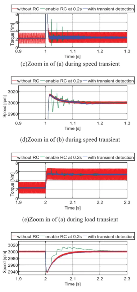
However, still, the interaction between speed PI and RC may cause oscillations during speed/load transients as shown in figure 5(green), where RC is kept on after being activated at 0.2s. Meanwhile, by properly disable only the learning process, the blue curve proves that the proposed transient detection strategy can reduce the oscillations while maintaining the reduction of torque ripple during the speed/load transients.
5 Conclusions
A novel combination of angle-based repetitive control (RC) and deadbeat current control (DBCC) is presented in this paper, aiming to effectively reducing periodic torque ripple under widely variable speed and even during speed/load transients. The DBCC, angle-based RC, torque estimator and the topology are chosen by considering the compensation of current control delays and the low-pass filter effect of mechanical system. Interpolations algorithms and a transient detection strategy are proposed to improve the accuracy of RC. The effectiveness of the proposed control topology is proven by simulation tests.
0 0.2 0.4 0.6 0.8 1
0 10 20
Time [s]
To
rque [N
m]
without interpolation proposed time/angle conversion
(a)Torque
0 0.2 0.4 0.6 0.8 1
2960 2980 3000
Time [s]
S
peed [rpm]
without interpolation proposed time/angle conversion
(b)Speed
0.8 0.85 0.9 0.95 1
2 4 6 8 10
Time [s]
To
rq
ue [Nm]
without interpolation proposed time/angle conversion
(c)Zoom in of (a)
0.8 0.85 0.9 0.95 1
2985 2990 2995 3000
Time [s]
S
peed [rpm]
without interpolation proposed time/angle conversion
(d)Zoom in of (b)
Figure 4: The performance of the proposed time/angle conversion
0 0.5 1 1.5 2 2.5 3
0 2 4 6 8
Time [s]
To
rq
ue [Nm]
without RC enable RC at 0.2s with transient detection
(a)Torque during speed/load transients
0 0.5 1 1.5 2 2.5 3
2900 2950 3000 3050
Time [s]
S
peed [rpm]
without RC enable RC at 0.2s with transient detection
[image:5.595.319.534.499.721.2] [image:5.595.64.266.658.765.2]0.9 1 1.1 1.2 1.3 0
2 4 6 8
Time [s]
To
rque [N
m]
without RC enable RC at 0.2s with transient detection
(c)Zoom in of (a) during speed transient
0.9 1 1.1 1.2 1.3
2980 3000 3020
Time [s]
S
peed [rpm]
without RC enable RC at 0.2s with transient detection
(d)Zoom in of (b) during speed transient
1.9 2 2.1 2.2 2.3
0 2 4 6 8
Time [s]
T
orque [N
m]
without RC enable RC at 0.2s with transient detection
(e)Zoom in of (a) during load transient
1.9 2 2.1 2.2 2.3
2940 2960 2980 3000 3020
Time [s]
S
peed [rpm]
without RC enable RC at 0.2s with transient detection
[image:6.595.54.275.84.552.2](f)Zoom in of (b) during load transient
Figure 5: The performance of the proposed transient detector
Acknowledgements
The authors wish to acknowledge the financial and technical support provided by the Shenzhen Best Motion Technology Limited, China.
References
[1] M Carpita, D Colombo, and A Monti, "A Generalised Approach to Torque Ripple Compensation In Permanent Magnet Machine Control," in Industrial Electronics, 2000. ISIE 2000. Proceedings of the 2000 IEEE International Symposium on, vol.2, pp. 396 – 400, (2000) .
[2] B.-J. Brunsbach, G. Henneberger, and T. Klepsch, "Compensation of torque ripple," in Electrical Machines
and Drives, 1993. Sixth International Conference on (Conf. Publ. No. 376), pp. 588 - 593, (1993).
[3] E. Favre, L. Cardoletti, and M. Jufer, "Permanent-magnet synchronous motors: a comprehensive approach to cogging torque suppression," Industry Applications, IEEE Transactions on, vol. 29, no. 6, pp. 1141 - 1149 , (1993).
[4] B H Lam, S K Panda, and J X Xu, "Torque Ripple Minimization in PM Synchronous Motors - An Iterative Learning Control Approach," in Power Electronics and Drive Systems, 1999. PEDS '99. Proceedings of the IEEE 1999 International Conference on, vol. 1, pp. 144 - 149, (1999).
[5] Lusu Guo and Leila Parsa, "Torque ripple reduction of the modular Interior Permanent Magnet machines using optimum current profiling technique," in Electric Machines and Drives Conference, 2009. IEMDC '09. IEEE International, pp. 1094 - 1099, (2009).
[6] J Holtz and L Springob, "Identification and compensation of torque ripple in high-precision permanent magnet motor drives," Industrial Electronics, IEEE Transactions oon, vol. 43, no. 2, pp. 309 - 320, (1996).
[7] Weizhe Qian, Sanjib K Panda, and Jian-Xin Xu, "Torque Ripple Minimization in PM Synchronous Motors Using Iterative Learning Control," Power Electronics, IEEE Transactions on, vol. 19, pp. 272 - 279, (2004).
[8] P. Mattavelli, L. Tubiana, and M. Zigliotto, "Torque-ripple reduction in PM synchronous motor drives using repetitive current control," Power Electronics, IEEE Transactions on, vol. 20, no. 6, pp. 1423 - 1431, (2005). [9] Li Wenshan, Zhang Jian, and Li Yong, "A simpler and
more efficient iterative learning controller for PMSM torque ripple reduction," in Electrical Machines and Systems (ICEMS), 2013 International Conference on, pp. 1231 – 1235, (2013).
[10] Y. Yuan, F. Auger, L. Loron, and S. Moisy, "Torque ripple reduction in Permanent Magnet Synchronous Machines using angle-based iterative learning control,"
in IECON 2012 - 38th Annual Conference on IEEE
Industrial Electronics Society, Montreal, QC, pp. 2518 - 2523, (2012).
[11] Zheng Enrang, China Xi''an, and Qiao Wei, "A ILC scheme and passive filter for PMSM speed control to minimize pulating torque," in Advanced Computer Theory and Engineering (ICACTE), 2010 3rd International Conference on (Volume:5 ), pp. V5-492 - V5-496, (2010).
[12] B. Lazhar, "On the compensation of dead time and zero-current crossing for a PWM-inverter-controlled AC servo drive," IEEE Trans. Ind. Electron., vol. 51, no. 5, pp. 1113-1117, (2004).