Improvements to a tool-chain for model-driven design
of Embedded Control Software
L.W. (Wilbert) van de Ridder
MSc Report
Committee:
Dr.ir. J.F. Broenink
Z. Lu, MSc
Dr.ir. R.G.K.M. Aarts
February 2018
005RAM2018
Robotics and Mechatronics
EE-Math-CS
University of Twente
iii
Summary
At the Robotics and Mechatronics (RaM) group of the University of Twente, we deal with in-creasingly complex cyber-physical systems. The software running on these systems, called Embedded Control Software (ECS), is a major contributor towards this increasing complexity. ECS is responsible for loop controllers, sequence controllers (finite state machines), resource intensive methods (e.g. SLAM), up to supplying means of user interaction. Additionally, these tasks are often distributed among multiple computational devices which requires some form of network communication.
To aid the design of ECS in a structured manner, a Way of Working (WoW) which encompasses a model-driven design approach has been developed at RaM. The goal of this WoW is to enable a first-time right implementation. To support this approach, a tool chain is available. Main components of this tool chain are LUNA (a hard real-time capable framework) and a GUI-based CSP modelling tool called TERRA. In the past few years, a number of additions have been made to this tool chain; to name a few: hardware ports, a ROS/LUNA bridge, and the mapping of CSP models created in TERRA to hardware using Clλsh.
The tool-chain does not seem to fit the requirements of the end-user as it is not used in projects very often. There appears to be a case of ’technology-push’ in contrast to ’market-pull’ from the perspective of the end-user.
In this project, the currently available tool-chain has been evaluated through use-case driven analysis. A number of missing or deficient features have been identified. For example, network communication between hard real-time (HRT) and soft real-time (SRT) layers in the system, methods to incorporate Finite State Machines, and co-simulation using Gazebo and 20-sim.
Finally, refinements made to the tool chain are demonstrated by design and implementation of embedded control software for the Production Cell. Additionally, some hardware extensions to the Production Cell based on previous prototypes have been developed to support.
A successful implementation using ROS and ZeroMQ-based network channels has been real-ised. Additionally, a proof of concept of HRT network channels using the CANBUS interface is available. A co-simulation approach, combining a LUNA-based application, Gazebo, and 20-sim in various topologies has been created.
v
Contents
1 Introduction 1
1.1 Context . . . 1
1.2 Problem statement . . . 3
1.3 Research questions . . . 3
1.4 Prior work . . . 3
1.5 Approach . . . 4
1.6 Report outline . . . 4
2 Analysis 5 2.1 Demonstrator . . . 5
2.2 MDD approach and tool-chain . . . 7
2.3 Conclusion & project requirements . . . 16
3 Tool-chain refinements 18 3.1 Communication links . . . 18
3.2 Finite State Machines . . . 20
3.3 Co-simulation . . . 20
3.4 Platform support . . . 22
4 Integration tests: Production Cell 4.0 23 4.1 Architecture and dynamic behaviour . . . 23
4.2 Model-based control law design . . . 23
4.3 Embedded Control System implementation . . . 25
4.4 Realisation . . . 27
4.5 Discussion . . . 28
5 Conclusions and recommendations 30 5.1 Conclusions . . . 30
5.2 Recommendations . . . 30
A Production Cell I/O requirements 31 B RaMstix timing characteristics 32 B.1 Test results . . . 32
B.2 Performing time measurements on RaMstix . . . 32
D Integration of IBM Rhapsody OXF 35
E Periodic Timer implementation 36
F Developing for Xenomai 3 38
F.1 HRT Applications . . . 38
F.2 HRT Drivers . . . 39
F.3 HRT OS . . . 39
G RaMstix I/O test utility 40 H Co-simulation example 41 H.1 Benchmarks . . . 44
I TERRA Hardware Ports 45 I.1 Port descriptions . . . 45
I.2 Notes for building TERRA generated LUNA applications . . . 49
J LUNA Components 50 K Production Cell: Quality Control Module 52 K.1 Sorter module . . . 52
K.2 Camera module . . . 55
L Models of the Production Cell modules 56 M Module performance requirements 57 N Production Cell <-> RaMstix Hardware Interface 58 N.1 Interface board . . . 59
N.2 Pin map for RaMstix #1 . . . 60
N.3 Pin map for RaMstix #2 . . . 62
O Practical Notes and Recommendations 63 O.1 Demonstrator . . . 63
O.2 LUNA . . . 63
O.3 TERRA . . . 63
O.4 20-sim . . . 63
O.5 RaMstix . . . 64
P Production Cell CSP Models 65
Q Production Cell Finite State Machine Models 70
CONTENTS vii
S 20-sim co-simulation plugin 77
S.1 Source code . . . 77
T ECS Management Daemon 82
U Appendix 4 - Running the demo 83
V Acknowledgements 84
1
1 Introduction
1.1 Context
Contributing to the 4th industrial revolution, research at the Robotics and Mechatronics (RaM) group at the University of Twente (UT) involves increasingly complex Cyber-Physical Systems (CPS). Industry 4.0, a term coined by the German Research Centre for Artificial Intelligence (DKFI, 2011), refers to the trend towards increasingly interconnected systems (Figure 1.1). CPS, of which robots are a sub-class, or"smart" systems are co-engineered interacting networks of
physical and computational components(NIST (2017)). Robotic systems play an important
role at the RaM group. Advancements in computing and networking keep opening up new possibilities. As a consequence, design of robots becomes increasingly complex as well.
Figure 1.1:The four industrial revolutions to date. Source: Simio (2018)
Figure 1.2:MDD approach for embedded control software. Source: Broenink and Ni (2012)
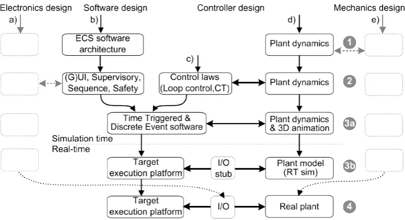
A methodology to create control software for robots has been developed at RaM (Figure 1.2). This Model-Driven Design (MDD) approach shapes the design process such that the resulting software should function the first-time right on the target hardware. This method consists of the following steps:
1. Architecture and dynamic behaviour 2. Model-based control law design
3. Embedded control system implementation 4. Realisation
First, the overall global architecture of the control software is constructed. This architecture should factor in the inclusion of control laws, supervisory and sequence controllers, (graphical) user interfaces (UI), and safety layers. In the second and third step, each part of this high-level architecture is refined using an iterative approach until all requirements are met.
Second, a model of the plant can be used to design and test control law implementations. For example, this could be a loop-controller responsible for a single component. Or, higher level sequence and supervisory controllers which govern the behaviour of one or more components and coordination amongst them. These controllers can be designed and verified using ideal models in isolation at this stage.
Third, the ECS is implemented through integration of the controllers from step 2, safety, error, and maintenance facilities. This can be validated against a plant model, which can be refined to include relevant non-ideal behaviour. The ECS can be implemented on the target execution platform while still connected to the virtual plant (a simulation of the robotic system).
CHAPTER 1. INTRODUCTION 3
Figure 1.3:Software architecture for embedded systems. Source: Broenink and Ni (2012)
1.2 Problem statement
A tool-chain has been developed to support the MDD approach. However, it is often not used in projects at RaM. From an academic perspective, the tool-chain contains unique features which aid designers of ECS. However, there appears to be a case of ’technology-push’ in contrast to ’market-pull’ from the perspective of the end-user. This means there supposedly is a mismatch between what the end-user desires and what the developers assume the end-user needs.
1.3 Research questions
The main research question is:
Does the tool-chain fit the needs of the end-user when designing embedded control software for a robotic system?
To answer this question, the following sub-questions have been devised:
• What features are currently deficient or missing in the tool-chain? • Which features can be added or improved?
• What use-case serves well to demonstrate the improvements to the tool-chain?
1.4 Prior work
The current state of the tool-chain is the result of years of research. In this section, prior work most relevant to the tool-chain and way of working will be discussed.
Broenink and Ni (2012) present a software architecture for embedded systems (Figure 1.3). The architecture separates the continuous time (CT) domain (the plant) from the discrete event (DE) domain. I/O hardware connects these two domains. The DE portion encompasses the ECS. The architecture consists of different layers. Filtering and scaling of the input and output signals is performed in the Measurement & Actuation block. Signal checks and overrides, for example implementing emergency stops, reside in the Safety layer. Complex algorithms, i.e. SLAM or image processing, typically belong to the Supervisory layer. Sequence controllers, often implemented as finite state machines, can use the input from Supervisory controllers to determine the next task. Finally, the Loop controller computes the outputs to the actuators based on sensor input from the plant and setpoints given by the Sequence controller. Typically, the closer a layer is to the hardware, the more strict the computational timing requirements.
locks. This is used to be able to guarantee that processes are executed before their deadlines,
res-ulting in hard real-time software execution(Bezemer and Broenink (2015)). To aid the design of
CSP models, a graphical tool suite called TERRA is available (Bezemer et al. (2012)).
Several approaches of integrating Finite State Machines in the tool-chain have been investig-ated. In the work of Ran et al. (2012), FSMs are transformed (manually) from UML to TERRA CSP. Meijer et al. (2013) looks at StateChart XML (SCXML) to describe state charts. 20-sim and TERRA import plugins were created. While CSP can be generated from SCXML through model-to-model transformation, Trillhose (2016) notes that these approach yield considerable over-head and deems them not practically usable on the RaMstix platform.
Bezemer and Broenink (2014) adds the ability to use hardware ports to TERRA, alllowing actu-ators and sensors to be interfaced with from within TERRA.
The first network channel designed for LUNA results from the work of Kempenaar (2014). Two applications could are able to communicate over a network channel. However, a daemon ap-plication is required on both ends. The apap-plications on either side have to communicate with the daemon residing on the same embedded board through shared memory objects.
Bezemer and Broenink (2015) & van der Werff and Broenink (2016) developed the ROS/LUNA bridge. The Robotic Operating System (ROS)(Quigley et al. (2009)) middleware is popular in the field of robotics. The ROS/LUNA bridge aims to connect to this middleware by the use of a so-called shapeshifter node. This node allows for subscribing to / or publishing dynamically. Normally, topics and message types have to be known at compile time when using the c++ interface. The shapeshifter node uses python to for dynamic behavior.
Kuipers et al. (2016) maps TERRA CSP to hardware using the functional language CλaSH. This
allows hard real-time functionality to be moved from the embedded processor a FPGA.
Addi-tionally, TERRA is extended to support conversion from CSP model to CλaSH.
Lu and Broenink (2017) propose a co-simulation approach where the Functional Mockup In-terface (FMI) standard is leveraged to co-simulate a software controller with modelled physical plant dynamics. A Functional Mock-up Unit is transformed to a CSP model. Additionally, CSP is used to formulate the master algorithm which orchestrates the communication amongst all FMUs.
1.5 Approach
A scenario for a robotic system will be designed. This scenario should be relevant for projects at RaM. For the robotic system, a demonstrator will be used. A demonstrator is a robotic system which is specifically designed to showcase control implementations.
The tool-chain will be analysed based on the designed scenario and its requirements. Within the scope of the scenario, missing or deficient features need to be identified. This results in an overview of desired improvements.
Next, a selection will be made from the set of desired improvements such that if successfully implemented, a realisation of the demonstrator scenario should be viable. Design and imple-mentation of the features will be done.
Finally, an implementation of ECS on a demonstrator according to the scenario will be carried out. Goal of this step is to demonstrate the effectiveness of the improved tool-chain.
1.6 Report outline
5
2 Analysis
In this chapter, a robotic setup (demonstrator) is presented in the first section as a use-case which requires design and implementation of ECS. Next, the use-case is used to conduct an analysis of the tool-chain to uncover missing or deficient features from the perspective of end-users (i.e people at RaM who need to design ECS for a robotic system). Finally, the requirements of this project (which follow from the analysis) will be discussed.
2.1 Demonstrator
2.1.1 Description
In this project, a demonstrator is used to provide a use-case of design and implementation of embedded control software.
The desired setup is illustrated in Figure 2.1. The setup represents a Production Cell modelled after a plastic-injection molding plant (van den Berg (2006)). It mimics a production-line where unprocessed products (shown as cubes) are placed on a conveyor belt (1). The processing step is denoted by (2,3). This is done by pushing the block into a confined space. Once processing is complete, the now completed product (cube) is extracted using a robot arm (4) and placed on an extraction belt (5). Finally, a quality control section is present which consists of a camera module (7) which detects faulty products and a sorting module (8) which removes the detected faulty products.
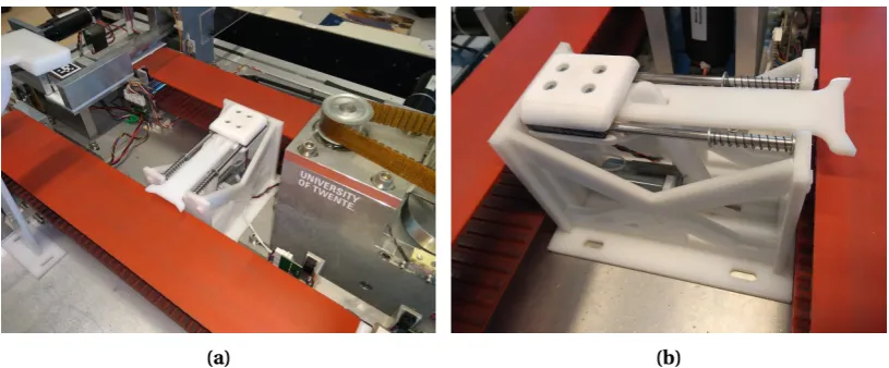
Figure 2.2b illustrates the hardware of the demonstrator. The first six modules are: Feeder belt, Feeder, Molder, Extractor, Extractor belt and the Rotation Robot. Also, limit switches are loc-ated on several modules to aid in calibration. Proximity sensors (for block detection) in the form of distance ranging and light bridges are at hand. The Extractor and Rotator modules are fitted with electronic magnets which can be used to handle the metal blocks. Appendix A lists the exact I/O specifications of the Production Cell. The final two modules (camera and sorter) have been added to the Production Cell in a previous project by Vos (2015). However, recom-mendations have been made to further integrate the sorter and camera module into the setup and improve its performance. As such, a new iteration of design and implementation of these modules must be carried out.
A survey reviewing recent projects at the RaM group provides insight in common character-istics between robotic systems which are present in the lab. Amongst projects that have been reviewed are the Roboship project (Borgerink et al. (2014)), SHERPA (Marconi et al. (2012)), I-botics (I-Botics (2016)), Aeroworks (Aeroworks (2014)), and PIRATE (RaM (2006)). Based on the survey, the Production Cell is deemed a sufficiently complex robotic system, comparable to systems generally found at the RaM group.
2.1.2 Embedded boards
Embedded boards to run the ECS should be divided up into one or more resource constrained (RC) boards for the HRT tasks (loop and sequence controllers) and one or more Resource Rich (RR) boards for the SRT tasks (GUI and supervisory control). RC boards are typically con-strained in power usage and size (e.g. an Arduino or Raspberry Pi). An RR board (e.g. desktop computer) is frequently located not on the robot itself (especially if the robot is small and mo-bile), utilizing a network to communicate with the RC boards. In this project, the RC boards
need to support the LUNA framework. LUNA supports both the commercial QNX1and the free
open-source Linux2operating systems.
Figure 2.1:Schematic overview of the demonstrator. 1: feeder belt, 2: feeder, 3: molder, 4: extraction robot, 5: extraction belt, 6: rotation robot, 7: sorter, 8: camera.
(a) (b)
Figure 2.2:(a) The Production Cell. (b) Layout of the Production Cell.
A number of embedded boards to run HRT tasks already have been compared to the default PC/104 stack in a previous project (Trillhose (2016)). Considered were the RaMstix (a custom ARM based board, developed at the RaM group), Arduino, and Rasperry Pi. It was concluded that the PC/104 stack was the only viable option to run a LUNA based application in a HRT con-text. However, the RaMstix has since been updated with a new Linux distribution and Xenomai 3 support. Also, it is used in a number of other projects and expert knowledge is available. The PC/104 hardware is considered End-of-Life, it runs a commercial operating system (QNX), and has less resources than the RaMstix w.r.t CPU and Memory. The Arduino is not suitable since LUNA does not support that platform. The Raspberry Pi currently has no support for Xenomai 3 and HRT capable I/O drivers.
CHAPTER 2. ANALYSIS 7
Figure 2.3:Software architecture for Production Cell.
2.1.3 Software Architecture
A high-level software architecture is designed given the requirements for the use-case, scen-ario, and available hardware (Figure 2.3). Multiple embedded boards will be used to run the loop and sequence controllers in the hard real-time domain. The controllers will be imple-mented by means of a LUNA based application. Some form of networking is required to allow for communication amongst these boards. ROS running on a Resource-Rich board will serve as the middleware to run supervisory controllers and a user interface. A network connection between the HRT and SRT domain is required.
2.2 MDD approach and tool-chain
Each step in the Way of Working (Figure 1.2) is reviewed to determine to what extend it is sup-ported by the tool-chain.
2.2.1 Architecture and dynamic behaviour
ECS software architecture
The global embedded control software architecture (Figure 2.3) cannot be captured in a model which can be used for formal verification and code generation. However, while formal verific-ation is desired for the HRT layers in the ECS, the complexity of the layers in the SRT domain makes this infeasible and likely not worth the time and effort (depending on the application). Some work is being done for describing architecture in the SRT (ROS) layers based on the 5C principle (Bruyninckx et al. (2013)). Ellery (2017) establishes a method on how to generate ROS nodes from a meta-model. However, this tooling is not mature enough to apply it already.
Plant dynamics
Bond graphs are the preferred method of describing plant dynamics at the RaM group. Bond graphs are port based, describe energy flow, and provide an intuitive way to express dynamics spanning multiple domains (Breedveld (1985)). Robotic systems often span, but are not limited to, the mechanical and electrical domains. Bond graphs consist of directed graphs describing both the dynamic structure and behaviour of the plant.
Figure 2.4:Model combining continuous time domain described using bond-graphs and discrete do-main described using a block diagram. The model depicts a disk mounted to a motor with gearbox, controlled by means of a discrete PID controller.
2.2.2 Model-based control law design
Loop control
Once the plant dynamics have been captured, loop controllers need to be designed and tested. 20-sim supports design and implementation of discrete controllers which can be connected to continuous time (CT) bond graph models.
Sequence control
A sequence controller can be implemented as a finite state machine. For the demonstrator, each of the six main modules would require a state machine to govern the behaviour of the loop controller. In addition, some modules have to communicate with each other to coordinate their actions.
In the ideal case, a model formalism for the state machine would be used which would allow for formal verification, and code generation.
Several projects in the past dealt with the implementation of FSM support in the tool-chain: Ran et al. (2012) (UML to FSM), Meijer et al. (2013) (SCXML), and Trillhose (2016) (UPPAAL). However, none of these approaches allow for either formal verification or code generation. Ad-ditionally, the tools are not considered user friendly.
In this project, the IBM Rhapsody tool is considered as it provides an easy to use graphical user interface based method to design finite state machines. Additionally, code generation is supported.
Supervisory control and Interaction
ROS has built-in networking capabilities in the form of publishers/subscribers, and service calls which resemble remote procedure calls (RPC). These capabilities can be used to connect any number of nodes (applications) within the same network.
User Interface
The User Interface can be designed and tested in isolation during this step. Any interfaces to the rest of the ECS can be mocked (mimic behaviour) until integration with components to be interfaced with is possible.
CHAPTER 2. ANALYSIS 9
There are approaches towards GUI development which are explicitly supported by ROS. Glade
in combination with PyGTK3is a popular choice which is based on Python. Another option is
the QT framework based on C++. This QT provides specific support for ROS, by means of the
ros-<distro>-qt-createandros-<distro>-qt-buildpackages.
The RobotWebTools project provides a WebSockets4 interface through a ROS node. In
par-ticular, the RosBridge Suite in combination withroslibjs5. This WebSockets interface can be interfaced with from any web-compliant application.
2.2.3 Embedded control system implementation
In the ECS implementation step, the isolated components developed in previous steps are in-tegrated and tested.
This means that since the ECS runs on multiple embedded boards, networking facilities must be available in this step.
To verify a correct implementation of the ECS, a simulation environment containing a compet-ent model of the whole plant should be created. The ECS can be interfaced with the simulation for testing and verification.
First, the ECS can be run on any platform in a software in the loop (SITL) topology. Once this step works as intended, the ECS can be implemented on the target hardware. Then, the ECS can still be interfaced with the simulation in a hardware in the loop (HITL) topology.
Loop and sequence control
Figure 2.5:Timing in hard real-time sys-tems.
The loop and sequence controller can be integrated into a single LUNA based application using TERRA. The loop controller can be exported from 20-sim using model-to-model transformation. For FSMs designed in Rhapsody, the generated code from the FMS model can be compiled to a static library, which can be linked and called from the LUNA based application.
The TERRA CSP models can be formally verified. The models can be transformed to a machine-readable CSP model (called CSPm). Assertions in the CSPm models, for example to check whether the model is deadlock free, can be checked using the FDR tool
(Thomas Gibson-Robinson (2014)). However, some constructs in the TERRA CSP models (like buffered channels) are not transformed properly to CSPm notation. This means that models containing these constructs cannot be formally verified.
Loop controllers, and possibly the sequence controllers, must be implemented in the hard real-time (HRT) domain. In this work, hard real-real-time means that the execution of a task within a given time frame is guaranteed (Bezemer (2013)). Note, it is not about performance or fast execution, but about determinism. For example, a loop controller may embody the task of a discrete PID controller (to give some system specific overshoot and settling time properties) designed to execute at a certain frequency. If the algorithm were to be executed at irregular intervals, or at a lower/higher frequency, its performance is likely non-optimal. Jitter refers to the deviation from the desired loop time (Figure 2.5). The range between the upper and lower acceptable loop times is called the acceptable jitter. Generally, the jitter and delay should be at least an order smaller than the bandwidth of the loop controller to ensure a good performance.
3http://www.pygtk.org/articles/pygtk-glade-gui/
Figure 2.6:CSP composition of two processes running at different loop rates.
Over- or underruns occur when the execution time is outside the accepted range. In hard real-time systems, this is considered a failure. Typical examples of HRT systems are vehicle control, air traffic control, and pacemakers. In the ideal case, components in the HRT layer can be formally verified for correctness.
Periodic timers implemented in LUNA are used to execute processes periodically. The current implementation only supports the QNX operating system and should updated to support Linux and Xenomai.
Some schemes seem to be impossible to implement using the currently available CSP con-structs in TERRA. Figure 2.6 illustrates a situation where some process sends values using an asynchronous (buffered) channel to another process running at a higher loop rate. An example would be a supervisory controller sending setpoints to a faster running loop controller. The sequence controller would run at a lower rate to minimise resource consumption. Unbuffered (rendezvous) and buffered channels as created now by TERRA are not suited for this type of communication. The buffered channels, as generated in c++ code by TERRA, block once the buffer is empty by default.
The buffered channels implemented in LUNA already support a non-blocking configuration. However, no TERRA support for this option is available and should be realised.
2.2.4 Supervisory control
At least two supervisory controllers, to deal with block detection and block position estimation, are required.
ROS nodes are suitable to run supervisory controllers. ROS nodes are generic c++ or python applications linked against the ROS libraries. This means that virtually any library (like OpenCV for vision tasks) available for these languages can be used. Additionally, the ROS ecosystem consists of a vast collection of ready-to-use nodes.
Network links
CHAPTER 2. ANALYSIS 11
Connecting LUNA to ROS is possible a number of ways. Depending on the capabilities of the embedded boards, the following topologies are possible:
• Using a bridge between ROS and LUNA.
• Integrate ROS natively on the resource-constrained boards.
In previous work, a ROS/LUNA bridge has been created (Bezemer and Broenink (2015) & van der Werff and Broenink (2016)). A bridge solution is advantageous when the HRT cap-able embedded boards do not have support for ROS directly. A disadvantage of this approach is the use of a custom protocol, which makes support and maintenance difficult compared to us-ing popular open-source third-party libraries. The current implementation of the ROS/LUNA bridge does have a few limitations: A fixed small buffer (∼500 bytes) severely limits the amount of messages that can be sent in a packet. If the buffer is not flushed in time, messages will be lost on the writer (LUNA) side. This can be solved by sending and flushing the contents of the buffer more often, but this requires more resources. Additionally, the ROS node on the other end of the bridge runs at a fixed polling frequency. The same buffer issue exists on this side, causing messages to be lost if the LUNA side sends messages faster than the ROS node can pro-cess. This implementation is possibly adequate for best-effort logging, but inadequate for e.g. communicating setpoints from a ROS node to the LUNA-based application.
The RaMstix does support ROS natively. It is possible to build applications and link them to
theroscpplibrary. That gives an application the ability to connect to the ROS network using
native methods. If the ROS library can be interfaced with LUNA channels directly, no custom protocols and bridges are necessary.
For network channels between LUNA applications, an implementation of HRT network chan-nels is considered. However, for a network channel to have HRT guarantees, a number of
plat-form and protocol requirements have to be met. The sectionReal-time capable operation
sys-temdescribes the platform requirements. Most notable are the required real-time drivers for
the network interface and real-time capable protocols. Table 2.1 depicts an overview of can-didate networking methods. Kempenaar (2014) provides an overview of wired Ethernet based options. It can be concluded that there are currently no options to create functional HRT net-work channels between LUNA applications running on different embedded boards. However, the CAN (Controller Area Network) interface has real-time (RT) driver support and provides a virtual interface. This means that the concept of HRT network channels based on CAN can be tested, albeit solely by running two or more LUNA applications on a single embedded board.
Interface / type RT protocol available? Xenomai Support? RaMstix RT driver support
Ethernet (wired)
Ethercat yes yes No
RTNet
TCP/IP No yes No
UDP Yes (udp only) yes No
PowerLink Yes Experimental No
Ethernet (Wi-Fi) No No No
CAN Yes Yes (rtcan) Virtual only
Table 2.1:Overview various networking methods.
For SRT network channels between LUNA applications, the following options are considered:
Figure 2.7:Network topologies based on various types of middleware.
• Use another library.
Earlier work (Kempenaar (2014)) presented an implementation of a network channel between two RaMstix boards. This implementation requires the use of a separate daemon process to be run on each board to be connected. The LUNA based application communicates with this daemon using shared memory objects. Preliminary tests show that this implementation is not user-friendly, does not have TERRA UI support, shows unstable behaviour (seemingly random crashes), and lacks documentation.
The ROS/LUNA bridge could also be used for LUNA to LUNA communication. However, this means the data exchange goes through the ROS network. This yields a solution which is limited in throughput and responsiveness.
Using native ROS channels for LUNA to LUNA communication would be possible. However, a ROS master node is required for service discovery. Data is sent directly between ROS publishers and subscribers. However, this approach is viable as long as ROS is used as middleware in the SRT layers of the ECS. If this is not the case, the requirement for a ROS master solely for communication between LUNA-based applications adds overhead.
Other third-party libraries have been considered which may be used to create network chan-nels for LUNA to LUNA communication. Several surveys exist in literature discussing net-working libraries in the context of robotics (Shakhimardanov et al. (2011), Lofaro et al. (2015), Niebuhr and Vick (2016)). ZeroMQ is often mentioned for its easy of use, high throughput, low latencies, and wide platform support. Based on these findings, ZeroMQ could be considered for network channels between two or more LUNA based applications.
Figure 2.7 shows the resulting topologies of the LUNA to LUNA SRT network channel candid-ates.
Co-simulation
To verify a correct implementation of the ECS, a (combined or single) model of the entire plant is required. For example, a complete model can be composed from the models used to design the loop controllers.
First, the model can be verified using a Software in the Loop (SITL) topology. Subsequently, the ECS can be implemented on the actual embedded boards. Then, Hardware in the Loop (HITL) Simulation can be carried out. The HITL simulation can only be used to test real-time beha-viour if the simulation can be stepped and communicated equal to or faster than the sample time of the controllers.
CHAPTER 2. ANALYSIS 13
limited. 20-sim only allows export of FMUs (functional mock-up units). Additionally, the in-tegration algorithms in the FMUs restricted to explicit inin-tegration methods (specifically: Euler and Runge Kutta 4).
The Gazebo simulator is considered (Foundation (2014)) in this project. The main reason is its popularity (Ivaldi et al. (2014)) and easy of use. However, Gazebo focusses on animation/visu-alization and supports only coarse-grained interactions. Its modelling capabilities for complex dynamic systems are limited Stojanovic and Dundee (2012). To that end, a co-simulation ap-proach using either 20-sim exported FMU (functional mock-up units) or a direct interface to 20-sim is considered.
Real-time capable operating system
Hard real-time execution of tasks requires operating system support. LUNA has support for the Linux operating system, which runs on the RaMstix. Applications on Linux can contain one or more tasks (also called threads) for execution. However, Linux by itself cannot run HRT tasks (Lelli et al. (2016)). The reason why Linux is not HRT capable by default is reviewed in this section. Furthermore, an overview is provided of options which makes Linux support HRT tasks. Last, the preferred option how to achieve hard real-time behaviour are discussed.
[image:21.595.340.511.365.494.2]Linux is by default not HRT capable because it is designed to favour throughput over determ-inistic execution times. Additionally, some kernel services like system calls and memory alloc-ation do not have deterministic behaviour w.r.t. their execution times.
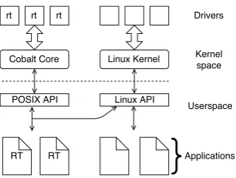
Figure 2.8: Xenomai Cobalt co-kernel ap-proach (Xenomai (2018)).
Solutions exist to make Linux applications run in a hard real-time context. The two most widely
em-ployed options are Preempt_RT6 and Xenomai7(Xu
et al. (2017)). Preempt_RT effectively patches the Linux kernel as where Xenomai changes the archi-tecture of the system by adding a co-kernel (called Cobalt) to the system (Figure 2.8).
At this moment, Xenomai allows for lower latencies during HRT task execution (Huang et al. (2017), Trill-hose (2016)). This is when compared to Preempt_RT on a single-cpu ARM based board (which closely matches the hardware available on the RaMstix). For this reason, Xenomai 3 is chosen as the preferred method to supply the system with HRT capabilities.
Using Xenomai has disadvantages. Special drivers, implementing Xenomai’s Real-Time Driver Model (RTDM), are required to allow HRT tasks to interface with hardware ( Kiszka (2005)). Ad-ditionally, hard real-time applications need to be compiled with explicit support for Xenomai. As development of Preempt_RT continues, it may be a more viable option in the near future since it does not require special drivers and build methods to achieve HRT behaviour.
To understand how Xenomai is able to facilitate HRT tasks, a few concepts are considered. First, how applications interface with Xenomai. Second, how Xenomai ensures it has priority over the Linux kernel. Third, the algorithms used to determine the order of execution of HRT and non-HRT tasks on a system. Last, some constraints have to be kept in mind when creating an non-HRT application.
Code that needs to run in HRT tasks is only allowed to use the POSIX API provided by Xenomai. While Xenomai provides a number of APIs (including an API to support applications which have been created for commercial real-time operating systems like VxWorks), in this project
we focus on the POSIX API alone. The main reason for this is portability. The Linux API is a superset of the POSIX API. This means that code can be shared between applications regardless if it needs to run in a HRT task or not. However, the POSIX API as provided by Xenomai is only a subset of the complete POSIX API. Code in HRT tasks which call functions provided by the Linux API only, cause the task to lose its HRT guarantees.
Figure 2.9:Xenomai interrupt and trap handling yagamy4680 (2014).
To ensure the Xenomai co-kernel is able to prioritize HRT tasks over other tasks, a custom in-terrupt pipeline (called ADEOS8) is used (Figure 2.9). The configuration of this pipeline ensures that any interrupts (e.g. from hardware) and traps (e.g. exceptions due to segmentation faults) are handled by Xenomai first. The Linux kernel does not receive any interrupts (due to a shield) as long as it is not allowed to run by Xenomai.
Figure 2.10: FIFO Scheduling method of HRT and non-HRT tasks when Linux is augmented with Xenomai.
Only a subset of the available types of tasks and scheduling methods are used in this project. For the real-time scheduler (belonging to the Xenomai Cobalt co-kernel), only the in, first-out (FIFO) scheduling method is used. Figure 2.10 depicts how these different types of tasks are scheduled.
The following types of tasks are used; in order of decreasing priority:
• (R)eal-time tasks.
• (W)eakly scheduled tasks. • (L)inux tasks.
The real-time scheduler schedules real-time tasks (which can have a priority level of 1-99, where 99 represents the highest priority task). Higher priority tasks will pre-empt lower-priority tasks if they become ready, meaning that the lower priority task will be suspended and put back in the waiting queue. If a real-time task executes a system call not provided by the Xenomai API, a mode-switch from the primary to the secondary domain happens. This means that the Linux scheduler will be invoked to execute that task while still shadowed in the RT scheduler.
CHAPTER 2. ANALYSIS 15
ing this time, all interrupts to Linux remain disabled, ensuring that execution of the task in the secondary domain is as fast as possible. However, there are no hard real-time guarantees for calls outside the Xenomai API. This will cause the task to lose its HRT properties and thus is to be avoided. Especially because other HRT tasks with the same or lower priority level cannot pre-empt this task, even though it is now scheduled by the Linux scheduler.
Weakly scheduled tasks (which can have a priority level from lowest to highest of 1 to 99) and Linux tasks (which can be scheduled in any way Linux is capable of, transparent to Xenomai) are only given a chance to execute when no real-time tasks are ready to run. Weakly scheduled tasks are special in the sense that they still have access to the Xenomai API (and as such, must originate from applications specifically compiled with Xenomai support), but are scheduled by the Linux scheduler by default (using the FIFO scheduling policy). The main use-case for these tasks is allowing synchronisation between HRT and SRT tasks.
The Linux tasks are scheduled by the Linux scheduler only. Linux tasks are only allowed to run when all HRT and Weakly scheduled tasks have finished. The Linux scheduler can be con-sidered an idle-task to the Xenomai scheduler.
Some considerations are important when creating HRT applications: Mode-switches of HRT tasks should be avoided at all costs. Third-party library functions can only be called from HRT threads if the library itself does not issue system calls not supported by the Xenomai POSIX API. Additionally, the library needs to be compiled with Xenomai support. When real-time threads use too much CPU time, starvation of weakly scheduled and Linux tasks will occur and can result in unexpected behaviour (e.g. unresponsive terminals, dropping network connections). Appendix F describes the steps required to create, build, and verify applications for Xenomai.
Communication (transferring data, i.e. through messages) between HRT and SRT tasks require decoupling mechanisms such that SRT tasks do not cause HRT tasks to lose their guarantees. An example would be for an SRT task to hold a lock (i.e. a mutex) which blocks a HRT task.
The following decoupling mechanisms are considered:
• lock-free queue + timed loop • lock-free queue + semaphore • Message pipes
The (fixed size) queues need to be lock-free to guarantee a constant execution time for the HRT tasks. Next, the properties of a timed loop, a semaphore, and messaging pipes is discussed.
The first option is to have a SRT task check the queue for messages, if there are none, sleep for a specific amount of time. The disadvantage is that this introduces a bounded delay for processing messages. This delay is directly related to the maximum time the task is configured to sleep. Additionally, precise timing is not guaranteed in the SRT domain, so the buffer might overflow. Also, it burns CPU cycles, even when no messages have to be processed. However, it can process batches if the loop keeps processing messages as long as the buffer is not empty. A low loop rate in combination with a large buffer can be efficient. The delay will be more prevalent in that case of course.
The second option is the use of a semaphore. The HRT task can signal a weakly scheduled task (it cannot be a Linux task, since the semaphore will be a Xenomai service) if it adds a new message to the queue. This will make the outgoing delay very small. However, this might not scale as well for large message rates as the SRT tasks can be signalled very often, especially if multiple HRT tasks produce messages.
Figure 2.11:Identified areas (1a: ROS-based channels, 1b: asynchronous channels, 1c: ZeroMQ-based channels, 1d: CAN-based channels, 2: Finite State Machines, 3: Co-simulation, 4: RaMstix platform support) in software architecture (left) and Way of Working (right) for which refinements to the tool-chain are desired.
Xenomai, it is by design not portable. For that reason, this option is not considered in this project.
RaMstix platform support
The software distribution for the RaMstix embedded board, which includes the operating sys-tem, has recently been upgraded. Xenomai 3 support is available and HRT capable applications can be run. However, a Xenomai 3 compatible RT driver is required to access the I/O capabilit-ies of the RaMstix through the FPGA. A real-time driver supporting an older version of Xenomai is available, but should be re-factored to support Xenomai 3.
No RaMstix I/O ports are available in TERRA. This means that custom code in each project is required to interface with the RaMstix ports. It would be convenient if a standard interface is available in TERRA for the following RaMstix I/O ports: encoders, PWM output, digital I/O pins, and analogue I/O pins. These ports could be added to TERRA.
2.3 Conclusion & project requirements
2.3.1 Conclusion
Desired improvements and additions to the demonstrator (the Production Cell) and tool-chain follow from the analysis.
A camera and sorter module need to be designed and implemented on the Production Cell setup. This straightforward mechatronic design process is described in Appendix K.
A number of missing or deficient features of the tool-chain have been identified. Most notable are communication links, finite state machines, co-simulation, and RaMstix platform support. The corresponding areas in the Way of Working and embedded software architecture are illus-trated in Figure 2.11. The requirements for this project are stated the following subsection.
2.3.2 Project requirements
CHAPTER 2. ANALYSIS 17
1) Communication links
1a There must be a ROS-based publisher/subscriber network channel implementation for LUNA.
• The ROS based network channel must be added to TERRA as a port.
1b There must be an implementation of an asynchronous channel.
• The asynchronous channel must be added to TERRA as a channel.
1c There must be a ZeroMQ-based publisher/subscriber network channel implementation for LUNA.
• The ZeroMQ based network channel must be added to TERRA as a port.
1d There could be a CAN-based publisher/subscriber network channel implementation.
2) Finite State Machines
• The Rhapsody OXF framework must be integrated with LUNA. • HRT behaviour of OXF must be analysed.
3) Co-simulation
• A method for co-simulation involving 20-sim and Gazebo should be created.
– A software in the loop (SITL) topology should be possible.
– A hardware in the loop (HITL) topology could be possible.
4) Platform support
3 Tool-chain refinements
From the analysis in chapter 2, it follows that a number of features need to be improved or added to the tool-chain. This chapter discusses each of these features. The communication link implementations are described in the first section. Then, the integration of the Rhapsody object execution framework with LUNA is discussed. Co-simulation methods are presented in section 3. Finally, the improved RaMstix platform support is reviewed.
3.1 Communication links
3.1.1 ROS-based network channel
Analysis & design
The UML diagram of the ROS implementation is shown in Figure 3.1. For the ROS-channels, the decoupling between the HRT and SRT side has been done using a lock-free queue and a timed loop. This queue is then processed by a worker thread (for the timed loop) which is set to a fixed update rate.
Figure 3.1:UML Diagram of ROS Channel implementation in LUNA.
Results
Appendix C lists a number of measurements comparing various network channel implement-ations.
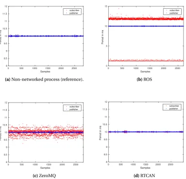
The ROS-based channels are properly decoupled from the HRT domain (Table A.1): no mode-switches were observed during operation. On the sender side, the mean value is exactly 10 000Hz, the standard deviation is 17µs. The largest deviation (jitter) observed is smaller than 0.1%
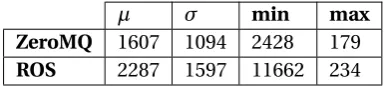
The round-trip time for ROS-based channels is∼2.2ms.
Conclusions
The ROS-based network channel provides a valid way of sending/receiving data to the ROS middleware in the SRT domain.
Further testing under load conditions and larger amount of publishers/subscribers is required to gain more insight in the behaviour of the ROS-based channels.
3.1.2 Asynchronous buffered channels
CHAPTER 3. TOOL-CHAIN REFINEMENTS 19
3.1.3 ZeroMQ-based network channel
Analysis & design
The UML diagram of the ZeroMQ implementation is shown in Figure 3.2. For the ZMQ-channels, the decoupling between the HRT and SRT side has been done using a lock-free queue and a semaphore. Upon writing to this queue, the thread writing a value to the queue also sig-nals a worker thread through a semaphore.
Figure 3.2:UML Diagram of ZeroMQ Channel implementation in LUNA.
The worker threads to send and receive messages are implemented using pthreads (POSIX threads).
Results
Appendix C lists a number of measurements comparing various network channel implement-ations.
The ZeroMQ-based channels are properly decoupled from the HRT domain (Table A.1): no mode-switches were observed during operation. On the sender side, the mean value is exactly 10 000Hz, the standard deviation is 17µs. The largest deviation (jitter) observed is smaller than 0.1%.
The round-trip time for ZeroMQ-based channels is∼1.6ms.
Conclusions
The ZeroMQ-based network channel provides a valid way of sending/receiving data to/from ZeroMQ subscribers/publishers in the SRT domain. Additionally, it can be used for best-effort communication between HRT modules. It needs to be emphasized that these channels are not HRT capable due to the non-RT capable network stack (drivers) on the RaMstix.
Further testing under load conditions and larger amount of publishers/subscribers is required to gain more insight in the behaviour of the ZeroMQ-based channels.
3.1.4 CAN bus
Analysis & design
A proof-of-concept of a HRT capable CAN channel implementation was implemented using two Xenomai applications. One sender at a fixed rate (100Hz) and one receiver. The send and receive operations (thus interfacing with a socket object) happened directly from a HRT tasks.
Results
Conclusion
The CAN bus is the only type of network channel for which a HRT driver is available, albeit a virtual interface. This suggests that a HRT network channel is possible between two or more embedded boards, if a HRT driver becomes available.
3.2 Finite State Machines
An integration of the IBM Rhapsody Object Execution Framework (OXF) with LUNA is now available. A brief high-level overview of the integration is provided in this section. Technical details of the implementation are described in Appendix D.
FSMs can be designed and tested in Rhapsody. Next, a static library can be build using the standard build files generated by Rhapsody. Subsequently, the functionality from this library can used from a c++ block generated by TERRA, like any other third-party library.
In fact, any c++ type class that can be generated using Rhapsody can be exported to LUNA. Algorithms designed using the FlowChart editor have been successfully integrated into LUNA based applications.
Finite State Machines exported from Rhapsody have been tested and were found to suit HRT tasks. No mode switches occurred during execution. Regardless whether asynchronous (events) or synchronous (Triggered Operations) were used, no mode switches were observed. This means that they can be used directly in HRT tasks. As such, the set POSIX functions called during execution from the OXF library and generated FSM is covered by Xenomai POSIX API. This includes the timer implementation of OXF.
3.3 Co-simulation
3.3.1 Design & analysis
For testing and verification of the ECS, a co-simulation approach has been implemented. Ana-lysis showed that the two main topologies would be software-in-the-loop (SITL) and hardware-in-the-loop (HITL). To simulate the dynamics of the plant using the models designed in earlier steps of the WoW, FMUs exported by 20-sim can be used, or 20-sim can be brought in the loop.
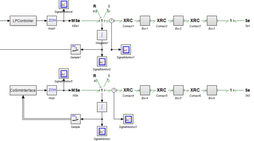
An example of a 20-sim-in-the-loop co-simulation approach is illustrated in Figure 3.3.
A simulation orchestration module is implemented in Gazebo as aWorldPlugin. This provides
the ability to start/stop/step the Gazebo simulation and update the models and world pro-grammatically.
The three main entities which are part of the co-simulation are:
• LUNA-based application. • Gazebo
• FMUs or 20-sim-in-the-loop.
The LUNA-based application is connected to the orchestration module through ROS or ZeroMQ ports. The subscriber port is configured as blocking read, such that the controller goes through an iteration upon receiving input from the orchestrator.
When 20-sim exported FMUs are used, they are instantiated as aModelPluginand connected
to a gazebo model. The FMUs are then executed in the model plug-ins by Gazebo itself.
CHAPTER 3. TOOL-CHAIN REFINEMENTS 21
and the 20-sim co-simulation plug-in DLL is made through ZeroMQ. ZeroMQs REQ/REP sock-ets are used to allow rendezvous like behaviour, meaning the 20-sim simulation will only step upon receiving data. See Appendix H for an example implementation.
The initialisation phase consists of the following steps:
• Instantiate FMUs / connect to 20-sim. • Obtain the initial values from FMU / 20-sim. • Update models with initial values.
• Check connection with Controller (LUNA-based application)
Then, the following step are repeated until the simulation is stopped:
1. Controller execution.
• Send the data to the controller.
• The controller executes once data is received.
• Retrieve data from the controller.
2. 20-sim / FMU model simulation.
• Send data to the FMUs / 20-sim.
• Step the FMUs / 20-sim.
• Retrieve data from the FMU / 20-sim simulation.
3. Update world.
• Update state of models, which dynamics have been simulated using external mod-els, in the world.
4. Step Gazebo simulation.
• Simulate gazebo models. For example, a camera.
• Advance the time by one step.
Figure 3.3:Co-simulation structure. On the left is a LUNA-based application. On the right a 20-sim-in-the-loop instance. Centered the simulation orchestrator, running within Gazebo as a plugin.
3.3.2 Results
Measurement data can be found in Appendix H.
This can be compared with the standard 20-sim XML-RPC interface. A standard call to this interface takes approximately 110ms. This means that the ZeroMQ interface for data-exchange during simulation is 100-500 times faster.
3.3.3 Discussion & conclusion
The simulation structure as presented here is only valid for system compositions which do not contain any cyclic graphs. I.e. all components can be stepped in some sequential order. The assumption on the 20-sim side (CT domain) is that the input does not change between the dis-crete timesteps. Of course, this is valid when a DE model is connected to this port at the correct frequency. This assumption will fail if for example another dynamical model is connected and supposedly interacts with the 20-sim model.
Gazebo is not a requirement for co-simulation. In fact, it is really only suited for visualisation purposes. Main reason for this is that its physics simulation is crude and most available sensors (like camera and LIDAR) are based on strongly simplified models. The orchestrator could be implemented in a separate application not dependent on Gazebo.
The current method is valid for specific type of system composition, as long as there is one CT and DE domain. There could be multiple CT domains, but they should not interact. The assumption currently is made that all DE subsystems run at the same rate.
The co-simulation approach using the 20-sim DLL is preferred in cases where models cannot be simulated accurately using the Euler and Runge Kutta 4 integration methods.
3.4 Platform support
To fully support the RaMstix board, a number of additions have been made to the tool-chain. First, a periodic timer implementation is discussed. Next, the RaMstix FPGA driver is discussed. Finally, RaMstix hardware ports are integrated into LUNA and TERRA.
3.4.1 Periodic Timer on Linux and Xenomai
The periodic timer implementation in LUNA has been improved to support the Linux and Xenomai platforms. The technical details and test results of the implementations are described in Appendix E. Tests show that a timer when running on Xenomai experiences a jitter of approx-imately 0.1% when a 1000Hz period is requested.
3.4.2 RaMstix FPGA Driver
The real-time FPGA driver for the RaMstix has previously been developed for Xenomai 2. How-ever, Xenomai 3 does not provide the same API. The driver is re-factored and now supports Xenomai 3. Appendix F provides background information on how to build applications and drivers for Xenomai 3.
A utility to allow for easy testing of the RaMstix I/O ports has been developed. It supports reading encoder values, setting PWM output values, reading the analogue and digital input pins, and writing to the analogue and digital output pins. Description and usuage instructions can be found in Appendix G.
3.4.3 RaMstix I/O ports in TERRA
23
4 Integration tests: Production Cell 4.0
The new or improved features tool-chain are tested by applying the Way of Working (WoW) towards design of ECS for the demonstrator. After each step in the WoW, the corresponding requirements from Chapter 2 are reviewed.
First, each of the four steps in the WoW and their application is discussed. Finally, a conclusion is provided to determine whether all requirements regarding the new and improved features for the tool-chain are met.
4.1 Architecture and dynamic behaviour
4.1.1 ECS architecture
Figure 4.1:Realised software architecture for Production Cell.
The high-level architecture of the ECS is illustrated in Figure 4.1. The modules, which each tonain a sequence and loop controller, are divided into two sections as they need to be imple-mented on two RaMstix boards.
4.1.2 Plant dynamics
The plant dynamics of the six existing modules (feeder belt, feeder, molder, extraction robot, extraction belt, and rotation robot) have been captured in bond graph models (Figure 4.2a). The parameters for the models were obtained using system identification methods (briefly dis-cussed in Appendix L) and existing documentation. The model for the sorting module can be found in Appendix K.
4.1.3 Discussion
None of the improved functionality created during this project was involved in this step.
4.2 Model-based control law design
4.2.1 Loop controllers
For each module, a loop controller has been designed. All modules (except for the sorting mod-ule), use a second-order motion profile as reference. The profile characteristics (for instance: time to complete the motion) are based on a timing scheme which can be found in Appendix M.
(a)Production Cell module bond-graph model. (b)Top-level controller structure in 20-sim.
Figure 4.2
4.2.2 Sequence controllers
Additionally, FSM models for each module has been designed using IBM Rhapsody. The FSM models are presented in Appendix Q. All common functionality is grouped into base classes. State transitions are implemented using asynchronous events and timers.
4.2.3 Supervisory controllers
Two supervisory controllers have been implemented. One for block identification and one for position estimation of the blocks. Both controllers are implemented as ROS nodes.
Figure 4.3: Block with ArUco marker and human-readable ID.
The block identification controller subscribes to a topic which
is published by theusb_camROS package. Theusb_camnode
publishes a feed from the extraction belt camera. The blocks on the Production Cell are fitted with ArUco markers and a unique ID (to make them easily identifiable for humans), see Figure 4.3. The OpenCV 3 library library is used has support for AruCo markers. Through camera calibration and the known position of the camera on the setup, the location of a block on the belt can be determined. The output from this controller is a list of detected blocks. Each entry contains the ID and position of the block.
A block position estimator is used to determine when the sorting unit should be activated. Since the blocks, when in front of the sorter, are not in view any more of the camera, their positions
need to be estimated. The position estimator subscribes to the output from the block identi-fication controller (block id’s and position), and subscribes the encoder of the extraction belt through ROS topics. The output from this controller is single on/off signal which activates or deactivates the sorting module. The sorter module in the LUNA-based applications subscribes to this signal through a ROS topic.
4.2.4 GUI
The Graphical User Interface is implemented using MeteorJS1. MeteorJS is a framework which
aids in building JavaScript based applications. An advantage of this approach is that common web-development tools can be used, which are widely available. To interface with ROS, the RobotWebTools ROS package is used. This package provides a ROS node which implements a WebSocket interface. This interface is used to connect the MeteorJS application to the ROS framework.
CHAPTER 4. INTEGRATION TESTS: PRODUCTION CELL 4.0 25
Figure 4.4:High-level communication links in the ECS. Strokes with an arrow-head denote unidirec-tional communication.
4.2.5 Discussion
New features were used for design and implementation of the sequence controllers. The IBM Rhapsody tool proved to be useful into designing the state machines. Additionally, its ability to implement the contents of states in sub-classes through inheritance proved to be useful. This is because a lot of functionality is shared among the modules at the higher levels. Now, a change in top-level structure only has to be made at a single location. Also, compiling the generated code into a static library and including it in a LUNA-based application is straight-forward.
No formal verification of the loop and sequence controllers has been carried out. Partly be-cause TERRA cannot generate CSP models for FDR to check from architecture models due to missing support for architecture models and buffered channels (however, this functionality is being worked on). The other reason is that IBM Rhapsody cannot formally verify FSMs. One solution might be to recreate the structure in a tool like UPPAAL and perform the formal veri-fication there. However, this would require manual effort to keep the models synchronised.
4.3 Embedded Control System implementation
4.3.1 Time triggered & discrete event software
In this step, all components of the ECS which have been developed so far in isolation, are in-tegrated. The FSMs and Loop controllers are combined in a LUNA based application, which is responsible for the HRT portion of the ECS. Appendix P discusses the implementation of the LUNA based applications.
The high-level communication links in the ECS are illustrated in Figure 4.4.
The supervisory controllers and GUI are connected through the ROS middleware.
4.3.2 Co-simulation
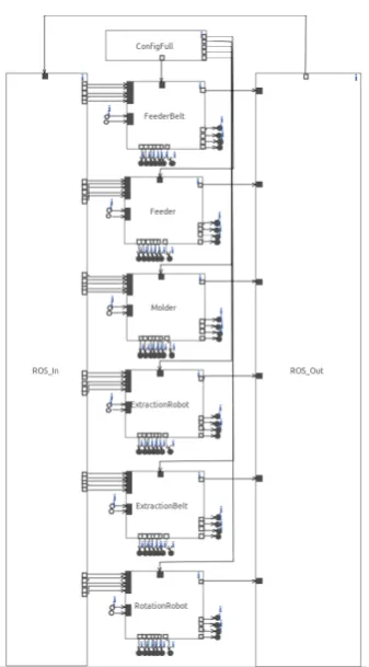
Figure 4.5:ECS CSP structure for simula-tion.
To test the ECS at this step, a simulation environment has been created. Subsequently, the ECS is connected to this environment.
The simulation environment has been created using Gazebo. The dynamics of all the hardware modules have been implemented using FMUs exported by 20-sim. A number of additional custom functionalities have been created for the Gazebo-based simulation, most notable: a light bridge sensor, a magnet model (for the rotation robot and the extraction robot), and a conveyor belt model. The 3D models of the mod-ules have been exported from the original SolidWorks models, and processed using Blender2, and finally im-ported into Gazebo. Figure 4.6 show screen-shots from the actual Gazebo simulation.
The top-level structure of the LUNA application used in simulation is depicted in Figure 4.5. For simula-tion, no timers are used, but the execution of the ECS is synchronised with the simulation steps in Gazebo. This allows for non-realtime simulation (either faster or slower).
Only software in the loop simulation has been conduc-ted. No hardware in the loop simulation has been per-formed. The reason for this is that this functionality only became available at the end of the project.
4.3.3 Discussion
The ROS integration into LUNA works as expected. The ROS-based network channels provide an easy way to monitor data in the HRT modules. Additionally, ROS services are used to trig-ger events on the FSMs in the sequence controllers, allowing the user to start/stop/reset the execution.
[image:34.595.329.498.107.412.2]2https://www.blender.org/
CHAPTER 4. INTEGRATION TESTS: PRODUCTION CELL 4.0 27
Figure 4.7:Device connection diagram.
Decoupling the sequence and loop controller through the asynchronous channels works as expected. Additionally, this lowers the resource usage on the RaMstix embedded boards having the ability to lower the execution frequency of the sequence controllers.
The ZeroMQ-based channels used to communicate the FSM state between the modules per-forms as expected. Especially between the feeder belt, feeder, and molder a tight communica-tion scheme is used to guarantee smooth processing of the blocks.
Creating the FSMs in Rhapsody appears to be a user-friendly method of implementing beha-viour for sequence controllers.
The ability to use co-simulation for testing of the ECS provided short feedback cycles during design. Since any changes to the ECS could locally (on a development computer) be tested in a SITL fashion without having to interface with the actual hardware, iteration times were shortened considerably. The FMUs exported from 20-sim were competent enough for testing the ECS. If more complex dynamics would be involved, which require for example variable step or implicit integration methods, we can use the ’20-sim in the loop’ co-simulation method.
4.4 Realisation
Finally, the ECS has been implemented on the target hardware. The structure is depicted in Figure 4.7.
An annotated illustration of the final setup is illustrated in Figure 4.8.
The interface module (a PCB board), which allows connection the RaMstix to the switching boards of the Production Cell, is documented in Appendix N. The Raspberry Pi has been added to run the ROS Master node. This allows for some decoupling between the RaMstix board and the Resource Rich board (the Intel NUC).
A complete cycle of one block in the system takes∼8s. This performance is more or less equal compared to previous implementations.
The loop controllers run at a frequency of 160Hz. The large amount of threads used by the LUNA-based application seem to cause a bottleneck due to overhead of context switching.
4.4.1 Discussion
Figure 4.8:Illustration of realised setup. 1: Feeder belt, 2: Feeder, 3: Molder, 4: Extraction Robot, 5: Ex-traction belt, 6: Rotation robot, 7: Sorter, 8: Camera module, 9: GUI, 10: Switching board, 11: RaMstix to Switching board interface module, 12: Resource-constrained board (RaMstix), 13: Resource-rich board (Raspberry Pi 3), 14: Resource-rich board (Intel NUC).
The RaMstix FPGA driver and the TERRA port interface has been used and works as expected.
The implementation of the ECS on the Production Cell was nearly first-time right. There were three main issues which required changes in the ECS:
• The blocks when transported by the Rotation Robot and Extraction Robot often fell off. The reason for this is that the arms began moving already when the blocks were not fully attached yet. In the simulation, it was assumed that the blocks attach instantly, while in reality it takes 20-30ms for a block to attach firmly after activation of the electromagnet. In this time frame, the arm already started moving, resulting in a loose grip on the block. This has been solved by adding a small waiting period (∼100ms) before the arm starts moving after the magnet activates.
• In the simulation, the camera output is a snapshot of the current state of the world. In reality, a camera does not record a frame instantly. Both rolling shutter and blurring ef-fects were not taken into account. This resulted in poor performance of the block de-tection algorithm on the actual setup. To mitigate the issue, the extraction belt has been slowed down to a speed where the block marker detection algorithm performed well.
• The positive direction of the Rotation Robot was switched in simulation. Meaning that in reality a positive direction was to the right, while in simulation it was to the left. This was adjusted in the ECS and simulation.
After these issues were fixed, the Production Cell performed as expected. All these problems were a direct result of an either too much simplified (for the camera and magnet) or wrong model (incorrect positive direction for the Rotation Robot). This emphasises the need to verify each sub-model in isolation.
4.5 Discussion
CHAPTER 4. INTEGRATION TESTS: PRODUCTION CELL 4.0 29
5 Conclusions and recommendations
5.1 Conclusions
The goal of this project was to determine whether the tool-chain fits the needs of the end-user when designing embedded control software for robotic systems. A demonstrator enabled a use-case driven analysis of the tool-chain to be conducted. This analysis identified a number of features, which were either missing or deficient in the tool-chain, which would be useful to end-users.
Consequently, three types of communication links have been created: ROS-based network channels for communication with the ROS framework in the SRT domain, ZeroMQ-based net-work channel for linking LUNA applications running on separate resource-constrained embed-ded boards, and a proof-of-concept of a CAN-based HRT capable network channel. Addition-ally, support for the IBM Rhapsody Object Execution Framework (OXF) has been implemented to allow for integration of Finite State Machines. Co-simulation support involving 20-sim and Gazebo is now available as well. Finally, platform support for the RaMstix has been improved.
At last, the improved tool-chain has been put to the test by creating an implementation of embedded control software for the demonstrator. A successful implementation has been achieved, showing that the additions to the tool-chain improved usability from the perspective of the end-user.
5.2 Recommendations
This section discusses a number of recommendations. Practical notes and recommendations are not discussed here and can be found in Appendix O.
For LUNA, research into efficient mapping of the CSP models to a combination of user threads and OS threads would be beneficial. For example, a mapping based on target platform (e.g. take into account the number of CPU’s available) could vastly increase the performance of the ECS. The main reason is that because currently every CSP group is mapped to its own OS thread. For large TERRA CSP models, a lot of OS Threads will be spawned, resulting a large overhead due to context switching.
In TERRA, support for the pri-parallel construct is desired, as it allows for more fine-grained control over process execution order and prevent starvation of high-priority tasks. CSP model generation for checking with FDR and animation support on the architecture level is desired for easier verification of the TERRA CSP models.
Other methods for designing FSMs could be considered. Formal verification of the FSM is cur-rently not possible. Either a method to generate a model from the FSM in Rhapsody which can be formally verified, or research into a FSM design tool which supports code generation and formal verification.
A more structured approach for co-simulation is desired. While the current method works, it is only usably in a limited number of use-cases. The FMI standard provides a structured ap-proach. While support for FMI by e.g. 20-sim is limited, it is expected to improve considerably in the near future.
31
A Production Cell I/O requirements
Hardware # devices I/O default I/O min I/O preferred
Maxon motors (through H-Bridge) 6 3 / 1 2 / 0 2 / 1
By default, to control the motors using a h-bridge two input pins would be required: PWM and direction. However, on the (custom) h-bridges used two additional pins are available: 1 brake/enable signal and one error-feedback. The brake/enable (high/low) pin could be con-nected to a 3.3V source such that it is always enabled.
Maxon encoders (quadrature) 6 0 / 3 0 / 2 0 / 2
The quadrature encoders have three outputs: A, B and I. A and B are used to sense position and are required. The I output, called a zero or index or reference signal, which supplies a single pulse per revolution. This single pulse is used for precise determination of a reference position. This additional output is not required for the Production Cell since end-switches are used for calibration.
IR Bridge 4 0 / 1 0 / 1 0 / 1
Motor endswitch 8 0 / 1 0 / 1 0 / 1
Electronic magnets 2 1 / 1 1 / 0 1 / 1
The input port is used to engage the magnet. The output port is used to verify that there is actually a current flowing. This output can be omitted if we decide not to require feedback on the magnets.
IR proximity sensor 2 0 / 1 0 / 1 0 / 1
Slotted optical switch 1 0 / 1 0 / 1 0 / 1
Camera (USB) 1 - -
-Stop button 1 1 / 0 1 / 0 1 / 0
Total 31 21 / 39 17 / 25 19 / 31