http://www.sciencepublishinggroup.com/j/jeee doi: 10.11648/j.jeee.20180605.11
ISSN: 2329-1613 (Print); ISSN: 2329-1605 (Online)
Assessment of Pilot Pollution Problem for Multi-Cell
Multi-User MIMO
Anahita Araghi
1, *, Mehran Pasebanpoor
21
Department of Electrical and Information Technology, Lund University, Lund, Sweden
2Department of Progress Engineering, Iran University of Science & Technology (IUST), Tehran, Iran
Email address:
*Corresponding author
To cite this article:
Anahita Araghi, Mehran Pasebanpoor. Assessment of Pilot Pollution Problem for Multi-Cell Multi-User MIMO. Journal of Electrical and Electronic Engineering. Vol. 6, No. 5, 2018, pp. 120-128. doi: 10.11648/j.jeee.20180605.11
Received: October 6, 2018; Accepted: October 26, 2018; Published: November 26, 2018
Abstract:
Focused research and standardization work in wireless throughput, subscribers will increase day by day. One can prospect that, millions of users in a mega city will want to transmit and receive data, for instance, 100 megabits per second per user. Massive MIMO (Large Scale Antenna Systems) is a new technology which will be used for resolving the mentioned issue. Spectral efficiency improvements over fourth generation (4G) technology are frequently mentioned. Adding more antennas is always beneficial for increased throughput, reduced radiated power, increase the capacity everywhere in the cell and greater simplicity in signal processing. In these days the main problem is RF interference and noise which can be generated by almost any device that produces an electro-magnetic signal, such as cordless phones to Bluetooth headsets, microwave ovens, repeaters and even smart phones, which is caused call drop and bad quality in the network. In this article, the Signal-to-interference-plus-noise ratio (SINR) and the value of mean capacity in the Non-cooperative cellular wireless have been increased by using infinite number of base station antennas. While employing advanced features, this is illustrated by network densification, Multi-cell Multi-User MIMO and inter cell interference mitigation techniques. The propagation model is not clear for both terminals and base stations which is calculated taking in to consideration path loss, specular reflection, environment models, earth’s elevation, fast fading, log-normal shadowing fading and geometric attenuation. The conjugate transpose of the channel estimation is used for forward and reverse precoding. Numerical results show that, by using unlimited number of antennas in the base station, the inter-cell interference, the effect of uncorrelated noise and fast fading have been vanished, although the inter-cell interference that caused by reuse of the pilot sequence in other cells does not disappear. And also average capacity improves with increment of base station antennas. In this study, MATLAB based simulation tool has been developed to calculate the SIR and also the mean capacity.Keywords:
Pilot Pollution, Multi-cell Multi-user, Multiple-Output and Multiple-Input, MIMO, SIR, SINR, MATLAB1. Introduction
Multiple-output and Multiple-input (MIMO) is a technology which is used multiple antenna at the receiver and transmitter. MIMO has been used in the hot topics of wireless communications for instance, IEEE 802.11n, IEEE 802.11ac, HSPA+, WiMAX, and LTE. Due to their impressive performance to bandwidth efficiency, one of the main mechanisms of future wireless communication systems are MIMO [2]. The MIMO technology is a low-cost alternative to increase throughput, such a system has the potential to
increase the power of processing [1, 3, 15]. For improving the data rate, a new MIMO design for molecular communication is proposed that develops multiple molecular emitters at the transmitter and multiple molecular detectors at the receiver [8]. The profits of MIMO systems have been widely approved and widely considered in recent years, due to the performance gains over single-input-single-output (SISO) systems. One popular application of MIMO techniques is to employ spatial multiplexing to improve the system capacity by sending parallel data streams across multiple transmit antennas [9].
transmission of a MIMO system [4-14]. By reducing or completely removing the Multi-User Interference (MUI), the base station uses the channel status information (CSI) in the sender so that these users can share the same channel. In this study, the Signal-to-interference-plus-noise ratio (SINR) ratio in a multi-purpose MIMO system which is have infinite number of base antennas in a multicellular environment is considered. And also from the data traffic evolution over the last years, high capacity requirement can be estimated for the next generation of mobile. It is cleared that approximately in 2020, a new fifth generation (5G) of mobile networks will be organized [6]. Multi-user Multiple-input Multiple-output (MU-MIMO) method, where several co-channel users connect with various number of antennas in base station can greatly increase the spectral efficiency of the wireless communication systems, and it has been implemented as an opportunity of transmission technique in 3GPP LTE-advanced. However, because the LTE standard allows for up to maximum 8 antenna ports, and also because the optimal transmission technique has infeasible computational complexity, the potential capacity of the Multi-user MIMO cannot be exploited completely in the current version of LTE standard. When the BS is equipped with a very large number of antennas, which is named as massive MIMO system, the spectral efficiency, power efficiency and Signal-to-interference-plus-noise ratio (SINR) can be improved greatly, even with very simple transmitter/receiver. Simulation results illustrates that the data rate of massive MIMO is approximately 24 times more than that of LTE-advanced. In these days, one of the hot topic in the research area of wireless MIMO communications is massive MIMO. For massive MIMO system, because the unlimited number of the antennas in BS, the achievement of the channel state information (CSI) is a main issue, mainly in downlink transmission [10-16].
Literature review
The concept of spatial multiplexing (SM) using Multiple-output and Multiple-input (MIMO) is proposed by Paulraj and Kailath in 1993 [14]. New methods for Multiple-output and Multiple-input (MIMO) technology have been found by Foschini which consist of multiple antennas in a transmitter to increase the link power effectively [13-3]. The MIMO antenna is transmitting independent and separately encoded data signals, known as "streams”, which can be improved the performance of the network.
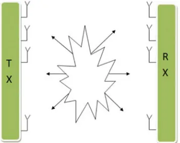
Figure 1. General MIMO system.
MIMO technology is one of the critical features of advanced wireless systems that play an important role in wireless communications. By increasing the bandwidth of wireless networks, users can send date with more speed than those without MIMO. According to Goldsmith, strong wireless security can be created by MIMO signaling features that don’t allow hackers to correctly detect all their signals that are broken and forwarded through multiple antennas along different paths [6].
2. Multiple Antenna Systems
A MIMO system usually uses M antennas in the transmitter and N antennas in the receiver in the same channel receiving direct components for each channel, as well as indirect components designed for other antennas, the time-independent and narrow band channel is assumed. The direct connection between antenna 1 in transmitter and antenna 1 in receiver is h11 and also h12 is the in a direct connection between antenna 1
and antenna 2, etc. The equation (1) shows transmission matrix H with dimensions N × M:
H … …
⋮ ⋮ ⋱
(1)
The equation (2) shows receive vector (Y):
Y=HX + N (2) Which X and N are transmitting vector and noise respectively.
Figure 2. MIMO transmission.
3. Design Multi-user MIMO
3.1. Propagation
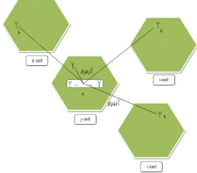
The propagation ratio between a single terminal antenna in one cell and the base station antenna in another cell is explained. The downlink and uplink transmission have the same propagation because of TDD (Time Division Duplex) operation and reciprocity. Figure 4 is shown the complex propagation ratio between N-th base station antennas in the l-cell, and the K-th terminal in the j-cell by hmjkl and βmjkl
which are equal to a complex fast fading factor and shadow fading.
g h ∗ β (3)
n= 1… N, k= 1… K, j= 1… J and l= 1… L
Where N and K are the number of base station antennas and users in each cell respectively.
Figure 4. The Propagation Coefficient.
3.2. Reverse -Link Data Transmission
K users transmit data in any cell. The communication from the user k in j-cell to other cells, which is caused the interference issue, is shown in Figure 5.
Figure 5. Reverse-link interference.
3.3. Received Signal
The received signal (x) is an N-by-1 vector containing transmission from all the users in the L-cell.
x ρr ∑ G a ω! (4) Where (a) is the message sending symbol which is shown K-by-1 vector from the users in l–cell, ω! is a receiver noise vector with zero components and also uncorrelated with the matrices belong to propagation, ρr is a measure of signal to noise ratio.
The base station processes is its received signal times to the conjugate transpose of the channel estimate, yields [8]:
y G#$x % ρ
&∑ G V ($% ρ)∑ G al+ ω! ( (5)
where the sign” †" means "conjugate transpose."
Figure 6. Forward-link interference.
3.4. Onward-Link Data Transmission
Each BS transmit a vector of message symbols through a pre-encoding matrix that matches the conjugate transfer of its estimate for the forward propagation matrix. In Figure 6 is shown the transition from the base station in I-cell to its k-th terminal interfere by transmission from base stations in other cells to their k-th terminals.
3.5. Pre-coding Matrix
The BS in the j-th cell transmits an N × 1 vector, ,-..∗/. , the ‘*' means" complex conjugate," ,-..∗ 0,-..123, and /.is message-bearing signals vector.
3.6. Forward Signal
All the L base stations transmit the K×1 vector that is received by K terminals in the l-th cell. The following function to calculate the forward signal should be used:
4̅6 78 ∑ ,:. .61,-..∗/. 9!6 [12] (6)
where 9!6 and 78 are uncorrelated noise and the forward SINR respectively, “T” denotes ”unconjugated transpose”.
4. Simulated vs Analytical Results
4.1. Signal-to-Interference Ratio for the Unlimited Number of Base Stations Reverse-Link
According to the above explanation, the ingredients of =. contain sums of inner products between N-component random vectors.
=. ,-..$ > 44̅. % 7?∑:6 ,.6 <.($ > % 7@∑:6 G.6 /A+ 9!.( (8)
According to the N increasing without any limitation, the noise effects disappear, and the inner products of the vectors are less dependent on the speed. For large N, only products of the same values remain, which is the matrixes that appear in both of the remaining expressions (9),
B,.6 $ ,.6 CD.6
3EFG 3EF
B CD.6+ (9)
Where Hjl is the N-by-K matrix of fast fading coefficients
between the K terminals of the l-cell, and the N antennas of the j-th base station, [Hjl]nk = hmjkl;, and Djl is a K-by-K
diagonal matrix whose diagonal elements contain the vector
%H̅.6(.I6 H.I6, K 1, … , M. As N is grown without bound,
BO.6$ O.6+ → QRSF F (10)
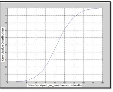
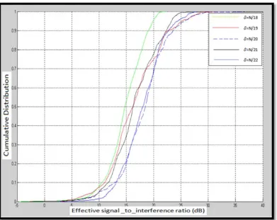
Where IK is the K×K identity matrix. The cumulative distribution (cdf) of the reverse effective the SIR (dB) is shown in Figure 7 the decay exponent is assumed γ = 3.8, and the shadow-fading standard deviation is σshadow = 8.9 dB.
The radius of cell is rc = 1000 meters, and the cell-hole radius
is rh = 100 meters.
Figure 7. Cumulative distribution (cdf) of the forward effective.
4.2. Forward-Link
The forward signal is calculated by the following formula,
4̅6 78∑ ,:. .61% 7?∑ ,:6 .6; <.(∗/. 9!6 (11)
The k-th terminal in the l-cell takes the following:
B TUTV4I6→ H6I6WI6 ∑ H6X. .I6WI. (12)
Signal-to-interference ratio is,
YQZ@I ∑ DF[FD
E[F
F\E (13)
identical expressions, so they have the same curve.
4.3. Signal-to-Noise Ratio for Limited Number of Base Stations
Matched filter precoder
In telecommunication, a matched filter is achieved by correlating a known signal with an unknown signal. This equivalent to multiplying the received signal with a conjugate-transpose of the channel estimate. The matched filter is the linear filter that maximized the output signal to interference ratio. The filter has been expressed as the impulse response of convolution systems. The signal to
interference plus noise ratio (SINR) is,
YQ]Z ^1E[[^
_∑[;\[ ^1E[;^ `a_∑F \E∑b[c^1EF [^ `aBd‖f[‖ (14)
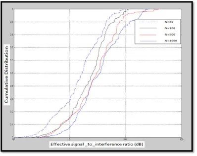
Figure 8 is shown a comparison of a different number of antennas in the MF precoding. Assume that each base station K = 10 serves the terminal. The cell diameter is 1000 m, and approaching the base station is not allowed by any terminal and then 100 meters, with the standard deviation σshadow = 8
dB and 7? 78 10 hi,
Figure 8. Cumulative distribution (cdf) for the MF pre-coder.
5. Zero Forcing Pre-coder
The signal processing of the space by which the multi-antenna transmitter can disable multi-player interference signals in wireless communications. ZF-precoding can achieve almost the capacity of the system when there is a lot of users. The Signal-to-interference-plus-noise ratio (SINR) is,
YQ]Z ^1E[[^
_∑[;\[ ^1E[;^ `a_∑F \E∑b[c^1EF [^ `aBd‖f[‖ (15)
As shown in Figure 9 there is a comparison between a different number of antennas in the ZF precoding; assuming that each base station serves K=10 terminals. The diameter of cell is 1000 m, and being close then 100 meters to the base station is not allowed, with the standard deviation σshadow = 8
dB and 7? 78 10 hi,
6. Regularized Zero Forcing Pre-Coder
Regularized zero-forcing precoding is enhanced processing to consider the impact of background noise. In the regularized zero forcing the conjugate-transpose of the channel estimate convert to the pseudo inverse G#$→ G#∗0G#$G#∗ Iδ2l .
The SINR can be described as formula (16),
SINR ^pqrr^
_∑r;\r ^pqr;^ `a_∑s \q∑rct ^pqs r^ `aud‖vr‖ (16)
Figure 9. Cumulative distribution for the ZF pre-coder.
Figure 11. Cumulative distribution for the regularized ZF pre-coder.
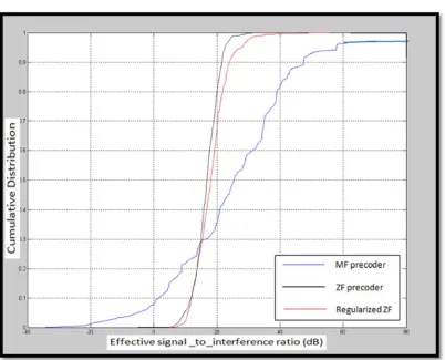
Between the different number of antennas in the regularized zero forcing, in each base station, K = 10 serves the terminal. The diameter of the cell is 1000 meters, and no terminal is allowed to approach the base station and then 100 meters, with the standard deviation σshadow = 8 dB and ρ& ρw
10 dB, which is shown in Figure 10 by comparing the three following methods, the number of users is K=25, and the number of base station antennas is N=1000, From the Figure 12 is recognized that the distribution of the SIR is more concentrated around its mean for zero forcing (ZF) precoding in compression with matched filter (MF) pre-coding.
7. MIMO Channel Capacity
The channel capacity is the amount of information that can be sent and received with the probability of undesirable error. The mean capacity is used as a measure for the spectral efficiency of the MIMO channel. The capacity of a random MIMO channel is,
C E|log+|1 SIR~~ (17)
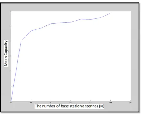
Figure 13. The Mean capacity for a different number of base station antennas.
The Figure 13 is shown the mean capacity for a different number of antennas, and recognize that by increasing the number of base station antennas the mean capacity increases.
8. Conclusion
The main goal of this paper was to increase the Signal-to-interference-plus-noise ratio (SINR) in the Non-cooperative cellular wireless with unlimited number of base station antennas. This system has the potential to deliver high throughputs on both the forward and the reverse link in fast-changing propagation environments. By using the unlimited
References
[1] Caire, Giuseppe, and Shlomo Shamai. "On the achievable throughput of a multiantenna Gaussian broadcast channel." IEEE Transactions on Information Theory 49, no. 7 (2003): 1691-1706.
[2] Dahlman, Erik, Stefan Parkvall, Johan Skold, and Per Beming. 3G evolution: HSPA and LTE for mobile broadband. Academic press, 2010.
[3] Foschini, Gerard J. "Layered space‐time architecture for
wireless communication in a fading environment when using multi‐element antennas." Bell labs technical journal 1, no. 2
(1996): 41-59.
[4] Gesbert, David, Marios Kountouris, Robert W. Heath, Chan-Byoung Chae, and T. Salzer. "From single user to multiuser communications: Shifting the MIMO paradigm." IEEE signal processing magazine 24, no. 5 (2007): 36-46.
[5] Golden, G. D., C. J. Foschini, Reinaldo A. Valenzuela, and P. W. Wolniansky. "Detection algorithm and initial laboratory results using V-BLAST space-time communication architecture." Electronics letters 35, no. 1 (1999): 14-16 [6] Goldsmith, Andrea, Syed Ali Jafar, Nihar Jindal, and Sriram
Vishwanath. "Capacity limits of MIMO channels." IEEE Journal on selected areas in Communications 21, no. 5 (2003): 684-702.
[7] Jungnickel, Volker, Konstantinos Manolakis, Wolfgang Zirwas, Berthold Panzner, Volker Braun, Moritz Lossow, Mikael Sternad, Rikke Apelfrojd, and Tommy Svensson. "The role of small cells, coordinated multipoint, and massive MIMO in 5G." IEEE Communications Magazine 52, no. 5 (2014): 44-51.
[8] Koo, Bon-Hong, Changmin Lee, H. Birkan Yilmaz, Nariman
Farsad, Andrew Eckford, and Chan-Byoung Chae. "Molecular MIMO: From theory to prototype." IEEE Journal on Selected Areas in Communications 34, no. 3 (2016): 600-614.
[9] Li, Ang, and Christos Masouros. "Exploiting constructive mutual coupling in P2P MIMO by analog-digital phase alignment." IEEE Transactions on Wireless Communications16, no. 3 (2017): 1948-1962.
[10] Ngo, Hien Quoc, Erik G. Larsson, and Thomas L. Marzetta. "The multicell multiuser MIMO uplink with very large antenna arrays and a finite-dimensional channel." IEEE Transactions on Communications 61, no. 6 (2013): 2350-2361. [11] Paulraj; Arogyaswami J. (Palo Alto, CA), Kailath; Thomas
(Stanford, CA); United States Patent; No. 07/839,624; 1992. [12] Marzetta, Thomas L. "Noncooperative cellular wireless with
unlimited numbers of base station antennas." IEEE Transactions on Wireless Communications 9, no. 11 (2010): 3590-3600.
[13] Raleigh, Gregory G., and John M. Cioffi. "Spatio-temporal coding for wireless communication." IEEE Transactions on communications 46, no. 3 (1998): 357-366.
[14] Vishwanath, Sriram, Nihar Jindal, and Andrea Goldsmith. "Duality, achievable rates, and sum-rate capacity of Gaussian MIMO broadcast channels." IEEE Transactions on Information Theory 49, no. 10 (2003): 2658-2668.
[15] Viswanath, Pramod, and David N. C. Tse. "Sum capacity of the vector Gaussian broadcast channel and uplink-downlink duality." IEEE Transactions on Information Theory 49, no. 8 (2003): 1912-1921.