R E S E A R C H
Open Access
Simple calibration method for dual-camera
structured light system
Chao Chen
1, Nan Gao
1and Zonghua Zhang
1,2*Abstract
A dual-camera structured light system consisting of two cameras and a projector has been widely researched in three-dimensional (3D) profilometry. A vital step in these systems is 3D calibration. Existing calibration methods are time-consuming and complicated because each camera-projector pair is calibrated separately. In this paper, an improved calibration method is proposed to decrease the calibration effort by simplifying the extrinsic calibration of one projector pair. It needs only two texture images to acquire the extrinsic parameters of the right camera-projector pair instead of 25 images (a texture image, 12 vertical, and 12 horizontal sinusoidal fringe patterns) and more complicated computations. A variant iterative closest point (ICP) algorithm was studied to match 3D cloud data sets for each camera-projector, and to reject outliers and invisible data automatically at each iterative step by using the proposed five criteria. Experimental results demonstrate that the proposed method is simple to operate and reaches the higher measurement accuracy of the shape data compared with the existing state of the art method.
Keywords:Calibration, Structured light system, Dual-camera, 3D shape measurement
Introduction
Three-dimensional (3D) shape measurement is an active topic in various applications such as reverse engineering, industrial inspection, augmented reality, and cultural heri-tage recording. Existing 3D measurement techniques in-clude stereo vision [1,2], laser scanning [3], interferometry [4] and structured light method. Among them, structured light is a very popular 3D shape measurement technique because of the advantages of full-field acquisition, fast data processing, low cost, and high resolution [5,6].
The simplest structured light system based on fringe projection [7] is usually composed of a camera and a pro-jector. The projector projects a series of fringe pattern im-ages onto the measured object surface. From another viewpoint, the fringe patterns are deformed with regard to the object surface and captured by a camera. The 3D shape of the measured object is obtained by using a tri-angulation technique. However, the measuring range is limited to the intersection of the camera-projector fields of view. Points not projected by the projector and/or ob-served by the camera cannot be measured. Moreover, the
camera resolution has its limits. On the contrary, a dual-camera structured light system [8] consisting of two cameras and a projector can increase the sensing range and its spatial resolution using each camera-projector pair to measure the partial area of an object.
Before performing the measurements, the dual-camera structured light system must be 3D calibrated, which builds the relationship between the phase map and shape data. System calibration can be divided into each camera-projector pair calibration. Next, the 3D data obtained from different viewpoints must be transformed into the same coordinate system. Calibration is very im-portant because it determines the optical and geometrical parameters of the projector and cameras. The existing calibration methods can be broadly classified into the following four categories [9]: geometric triangulation, polynomial method, inverse camera, and pseudo-camera methods.
Triangulation is formed by the imaging center of the camera, projection center of the projector, and the mea-sured object surface. Triangulation methods [10–12] at-tempt to establish the mathematical description of height using phase and the parameters of the system. These sys-tematic parameters include the distance between the im-aging center of the camera and projection center of the
* Correspondence:[email protected]
1School of Mechanical Engineering, Hebei University of Technology, Tianjin
300130, China
2Centre for Precision Technologies, University of Huddersfield, Huddersfield
HD1 3DH, UK
projector, distance between imaging center and a refer-ence plane, angle between optical axis of the projector and the camera, and period of the fringes. These methods are simpler than other calibration methods. However, it is dif-ficult to achieve parallelism between the line of optical centers and the reference plane. Moreover, the projection angle deflection and/or the projection lens distortion af-fects the measured results.
Polynomial calibration methods [13–16] build the rela-tionship of phase and depth by fitting a polynomial through N pairs of known phases and depths for every pixel. Usually, a plate with discrete markers with known separations is positioned successively at different posi-tions from the camera. A marked point on the first cali-bration plate is used as the origin of the world reference system; then the following calibration plates are chosen parallel to the first one. In this method, their displace-ments with respect to the first plane must be known. To obtain high accuracy, more plate positions are used to cover the measurement volumes and the order of the polynomial should be more than five, which means that there are too many coefficients to calculate. The main drawback of this calibration method comes from its practical limitations, such as its plate position restric-tion, the difficulty of calibrating a large measurement volume, and the long running time of processing and capturing the fringe pattern image data.
The goal of the inverse camera method [17,18] is to ob-tain the intrinsic and extrinsic parameters for the camera and projector of a 3D structured light system. Both cap-tured and projected images are generally described by a standard pinhole camera model with intrinsic parameters and extrinsic parameters from a world coordinate system to a camera or projector coordinate system. The key point of this calibration method is to consider the projector as an inverse camera (mapping intensities of a 2D image into 3D rays), so that the calibration of the projector is the same as that of a camera. Usually, this calibration method consists of the following five steps: (1) calibrating the in-trinsic parameters of the camera, usually using Zhang’s method [19]; (2) recovering the calibration plane in the camera coordinate system; (3) projecting a checkerboard image on a calibration board and detecting the corners of the captured checkerboard image; (4) applying ray-plane intersection to recover the 3D position of each projected corner; and (5) calibrating the projector using the corre-spondences between the 2D points of the projected image and the 3D projected points. The advantages of this method are that it is simple and fast. However, the disad-vantage is the coupling of calibration errors between the camera and projector. The projector calibration results hence depend on the camera calibration results.
To overcome the error coupling, a pseudo-camera method [20–23] was proposed that treats the projector as
the pseudo camera of a digital micro-mirror device (DMD) image. This method needs to establish the corres-pondence between camera pixels and projector pixels using the absolute phase. The advantage of this method is that the camera and projector are calibrated simultan-eously, so the coupling of calibration errors is avoided. The accuracy of the correspondence is one of the key fac-tors that influences the calibration accuracy. In Zhang and Yau’s method [23], a checkerboard is used to calibrate the dual-camera structured light system. However, the corner detection of a checkerboard is sensitive to illumination condition, leading to low accuracy and reliability.
To keep balance between calibration accuracy and time complexity, an improved calibration method is proposed to decrease the complexity of the calibration procedure by simplifying the extrinsic calibration of the structured light system. A white plate with a matrix of hollow black ring markers is used to calibrate the dual-camera structured light system. The system calibration process can be di-vided into three steps. 1) Calibrating the right camera and the structured light system with the left camera by estab-lishing corresponding point pairs between projector pixel coordinate and left camera pixel coordinate of discrete markers on a plate surface. The corresponding projector pixel coordinate of each marker is determined by measur-ing the absolute phase from projected vertical and hori-zontal sinusoidal fringe patterns on the plate surface. 2) Computing the transformation between left camera and right camera using intrinsic parameters of two cameras, the center of each marker coordinates in two camera im-ages and world coordinates of the center of each marker. 3) Calculating extrinsic parameters of the structured light system with the right camera using the aforementioned obtained parameters. 3D cloud data sets for the two projector-camera pairs obtained by the calibrated system are matched based on the variant ICP (iterative closest point) algorithm [24]. We simplified the system calibra-tion and achieved the high measurement accuracy by using the variant ICP algorithm. The rest of this paper is organized as follows. The principle and details of the proposed calibration method are described in Section
“Theories”. Experimental results are presented in Section
“Experiments and Results”. Section“Discussions”presents the conclusion and remarks about future work.
Theories
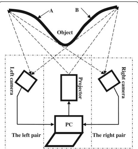
right camera and the left camera cannot observe areas A and B, respectively, because of the crossed optical axes of the projector and the camera. Therefore, a structured light system with a single projector and dual cameras has been developed to measure object surfaces.
This system contains two subsystems: one with the left camera and another with the right camera, called the left pair and right pair, respectively. Figure 1 illustrates how the system with the right camera cannot obtain area A of the object and the system with the left camera cannot ob-tain area B of the object. A projector projects the gener-ated fringe pattern images onto the measured object’s surface. The fringe patterns are deformed with respect to the object surface and captured by two CCD cameras from different views. The absolute phase of each pixel can be calculated from the captured fringe patterns. Two point cloud images of the measured objects are obtained from the absolute phase data after the system is calibrated. The two point cloud images from the different views can then be transformed into the same coordinate system.
Processing procedure of the proposed system calibration method
To calibrate the proposed system, the following three steps are applied.
1) Calibrating the intrinsic parameters of the proposed system. This step needs to calibrate the intrinsic parameters of the two cameras and the projector. The projector is calibrated by establishing the
corresponding point pairs between the projector pixel coordinates and the left camera pixel coordinates of the discrete markers on a plate surface. The same calibration plate is used to calibrate both cameras. 2) Computing the relationship between the two
cameras using the intrinsic parameters of the two cameras, center of each marker coordinates in two camera images, and world coordinates of the center of each marker. The transformation between the left camera and the projector is computed by establishing the relationships between the world coordinate system and the projector coordinate system as well as between the same world coordinate system and the left camera coordinate system.
3) Calculating the relationship between the right camera and projector using the obtained parameters. Three-dimensional cloud data sets for the two camera-projector pairs obtained by the calibrated system are matched based on the variant ICP algorithm.
Intrinsic parameter calibration
The intrinsic parameters of the projector and the two cameras must be calibrated before calculating the extrinsic parameters of the system. The intrinsic parameter calibra-tion method [20] has been applied because the coupling of calibration errors can be avoided. A projector is treated as a pseudo camera to be calibrated. To calibrate the pro-jector, a vital step is to establish the correspondence be-tween the projector pixels and camera pixels and convert a CCD image to its corresponding DMD image.
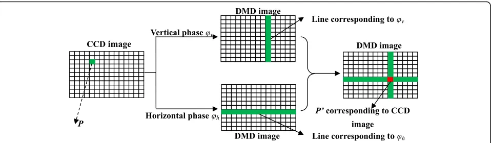
A calibration plate with discrete markers on the sur-face is placed randomly in the measuring volume. At each position, 12 vertical and 12 horizontal sinusoidal fringe patterns along with white illumination are pro-jected onto the plate surface. A CCD camera captures the fringe pattern images and a texture image under white illumination. After an absolute phase map is ob-tained by a standard four-step phase-shifting algorithm in conjunction with the optimum three fringe selection method [25], a unique point-to-line mapping between the CCD and DMD pixels is established. Assumeφvand
φhdenote the vertical and horizontal absolute phases of
pixel Pon the CCD image, as illustrated in Fig.2. If the vertical fringe patterns are applied, the line that corre-sponds to φv is a vertical line. If horizontal fringe
pat-terns are applied, the line that corresponds to φh is a
horizontal line. If both of them are applied, the intersec-tion of the lines on the DMD image is the pixel P′ cor-responding to the point on the CCD image. This one-to-one mapping between a CCD image and DMD image can be determined using above method.
Figure3illustrates how the circle centers of the DMD image are generated. The subpixel coordinates of each circle center on the calibration plate are accurately B
The left pair The right pair PC
A
Object
Pr
ojector
Rig
ht camera
Left camera
positioned according an ellipse fitting algorithm [26, 27] after extracting the inner and outer edges of each circle from the captured texture image. The absolute phase of the extracted circle center in the CCD image can be calcu-lated by linear interpolation along the vertical and hori-zontal directions, denoted asφmandφn, respectively. The
optimum three-fringe number selection method is used to obtain the absolute phase dataφmandφn, whose range is
related to the captured fringe number. The pixel coordi-nates of the corresponding point (m, n) in the DMD image can be computed as follows:
m¼Mφm
2πT þ
M
2 ð1Þ
n¼Nφn
2πTþ
N
2 ð2Þ
where M and N are the width and height of the
pro-jected fringe patterns. In addition, T is the projected
fringe numbers for phase calculation. All pixel coordi-nates of the corresponding points of all circle centers can be estimated for all plate positions. Then, the DMD pixel coordinates of the circle centers and the corre-sponding world coordinates are known, and the intrinsic parameters of the projector are determined using the
MATLAB Camera Calibration Toolbox [28]. In addition,
nine texture images of the calibration plates are used to extract circle centers to calibrate the intrinsic
parame-ters of the two cameras using Heikkila’s calibration
method [29].
Proposed system calibration method
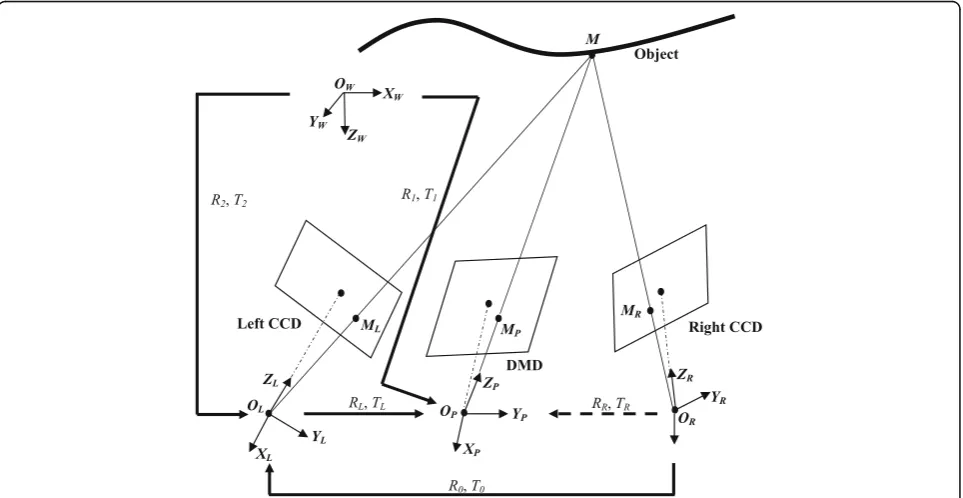
Separately calibrating each camera-projector pair is usu-ally time-consuming and complicated. Therefore, a novel calibration method is proposed to simplify the extrinsic calibration process of the right camera-projector pair. Figure 4 shows the coordinate system of the dual-camera structured light system. The world coordin-ate system (OW; XW, YW, ZW) is established withxandy
axes on the plane and the z axis perpendicular to the
plane and pointing toward the system. The projector co-ordinate system (OP; XP, YP, ZP), left camera coordinate
system (OL; XL, YL, ZL), and right camera coordinate
sys-tem (OR; XR, YR, ZR) are built withxandyaxes parallel to
image plane and the z axes perpendicular to the image plane and pointing forward from the optical center. The dot-dashed lines denote the left camera axis, the projector axis, and the right camera axis, respectively.
Assume a spatial point M is located in the left camera coordinate systemXl= (xl,yl,zl)T, right camera coordinate
system Xr= (xr, yr, zr)T, and projector coordinate system Xp= (xp,yp,zp)T. Here, []Tdenotes transposition. The
rela-tionship betweenXl,Xp,andXris described as follows:
Xp¼RLXlþTL ð3Þ
Xl¼R0XrþT0 ð4Þ
whereRLrepresents the 3 × 3 rotation matrix between the
left camera coordinate system and projector coordinate
system, and TLrepresents a 3 × 1 translation vector.
Fur-ther, R0represents the 3 × 3 rotation matrix between the
left camera coordinate system and right camera
coordin-ate system, andT0represents the 3 × 1 translation vector.
According to Eqs. (3) and (4),RRandTRbetween the right camera coordinate system and the projector coordinate system can be derived from the following equation:
Xp¼RRXrþTR ð5Þ
where
RR = RLR0
TR ¼ RLT0 þ TL
The system calibration procedure has three steps: (1) computing extrinsic parameters (RL,TL) of the left pair;
(2) computing the relationship (R0,T0) between the left
known from a previous calibration process, and hence ex-trinsic parameters (RR,TR) of the right pair is determined.
Calibration of the left pair
The extrinsic parameters of the left pair are calibrated using a unique world coordinate system for the two
cameras and the projector. The intrinsic parameters of the projector and left camera have already been cali-brated using a calibration plate with discrete markers on the surface, as described in Section 2B. The extrinsic pa-rameters are computed using the same coordinate pos-ition of the calibration plate to guarantee they are in the same world coordinate system.
Fig. 4Coordinate system of the dual-camera structured light system
Horizontal fringe
Absolute phase
Absolute phase Center position of markers
Pixel position in the DMD
Texture image
Vertical fringe
The left pair is calibrated by estimating the relation-ship between the projector coordinate system and world coordinate system as well as between the left camera co-ordinate system and the same world coco-ordinate system. Here, XM= (xw,yw, zw)T denotes the 3D coordinates for
pointM in the world coordinate system. These relation-ships can be described as:
Xp¼R1XwþT1 ð6Þ
Xl¼R2XwþT2 ð7Þ
where R1 represents the 3 × 3 rotation matrix between
the world coordinate system and the projector
coordin-ate system, and T1represents the 3 × 1 translation
vec-tor. In addition, R2represents the 3 × 3 rotation matrix
between the same world coordinate system and the left
camera coordinate system, and T2 represents the 3 × 1
translation vector. The plate positioned with different poses is captured by the two cameras. A total of nine images are used to obtain intrinsic parameters of the dual-camera structured light system. The extrinsic pa-rameters can be obtained by the same procedure as those for the intrinsic parameters of the two cameras es-timation. The only difference is that only one calibration image is needed to obtain the extrinsic parameters. We choose the plate image positioned with nearly
perpen-dicular to the DMD imaging plane to calculate R1, T1,
R2, and T2. The extrinsic parameters of the left pair,
de-noted by (RL,TL), can be deduced from Eqs. (6) and (7)
Xp¼RLXwþTL ð8Þ
where
RL¼R1R−21 TL¼T1−R1R−21T2
Calibration of the relationship between the left camera and the right camera
To obtain the relationship between the left camera and right camera, two images of the calibration plate are used. The circle centers of the two images are extracted. When the intrinsic parameters of both cameras, the pixel coordi-nates of all circle centers in both camera images, and the world coordinates of all circle centers are known, the rela-tionship (R0,T0) between the left camera and right camera
can be determined using the above method.
Calibration of the right pair
After obtainingRL,TL,R0, andT0in a previous calibration
process, RR and TR can be calculated using Eq. (5).
Three-dimensional cloud data sets for the two pairs are obtained using the calibrated intrinsic and extrinsic pa-rameters of the system [20]. Assuming the intrinsic
parameters of the system are unchanged, this calibration method can simplify the extrinsic calibration of the right pair. It needs only two texture images instead of 25 images (a texture image, 12 vertical, and 12 horizontal sinusoidal fringe patterns) and more complicated computations.
Data registration
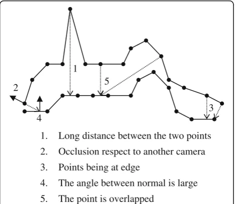
Ideally, each camera-projector pair should be in the same coordinate system for the same point. The match should then be automatic because the system is calibrated in the unique coordinate system. However, the real measured re-sults are not in the same coordinate system and are not matched well because of calibration error and/or measure-ment error. Therefore, it is necessary to register 3D data sets for the two pairs. Because the initial registration of the two data sets from two pairs is already known, regis-tration of the two data sets needs only to refine the match. We improve the registration by minimizing the sum of the square of the distances between matching points using a variant of the ICP algorithm. We introduce a method that uses multiple attributes of the sample points to get the true corresponding points. Figure5shows all incorrect cases that can occur during the iteration procedure. Each point denotes iteration point that may lead to the wrong alignment. It is located in three-dimensional spatial coordinate system. However, to make description more comprehensible, we express all incorrect cases in two-dimensional coordinate system.The following criteria must be satisfied, wherep1,iis in one data set andp2,iis in
the other data set, respectively.
1. Pointp1,iand pointp2,ishould be in exactly the
same position, i.e., the distance between the two
2 5
4
3 1
1. Long distance between the two points
2. Occlusion respect to another camera 3. Points being at edge
4. The angle between normal is large
points should be zero, in theory. In practice, their positions will differ somewhat because of many kinds of errors. We use a threshold operation for selecting candidate points in the two range images. The threshold value is twice the scanner’s resolution. Two points that are far away must be discarded from the list of candidate points, as shown in Fig.5(1). 2. Pointp1,iand pointp2,ishould be visible from each
other. Points have to be not self-occlusive or occlusive from another view, as shown in Fig.5(2).
3. Pointp1,iand pointp2,ishould not be at the edge. Boundary points are those points that lie on the edge of a triangle and these points will pull the mesh in the wrong direction, as shown in Fig.5(3). 4. Pointp1,iand pointp2,ishould have the same normal, in
theory. In practice, it is also impossible. Only those point pairs where the angle between their normal is less than 45 degrees are acceptable, as shown in Fig.5(4). 5. Whenp1,iis a point in the overlapping region of the
view, there should be one and only one
corresponding pointp2,iin another view, as shown
in Fig.5(5).
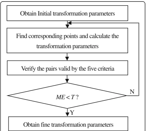
The registration procedure is described in an overall flowchart in Fig.6, whereTis a precision component of the criteria. ME denotes the mean square error of the corresponding point pairs in the two data sets.
There are two main steps of the variant ICP. The first finds the closest points using point-to-point Euclidean distance between two data sets. The second computes the transformation between two data sets. In addition, an initial rotation matrix RR and translation vector TR
are given before performing the registration.
Experiments and results Experimental system
The developed measurement system is composed of two CCD cameras and a projector, as illustrated in Fig. 7. The projector (CP270, BenQ) has a one-chip digital DMD. Its native resolution is 1024 × 768 pixels (XGA). The red, green, and blue colors are produced by rapidly spinning a color filter wheel in the projector and syn-chronously modifying the state of the DMD. The two cameras (ECO655CVGE, SVS-VISTEK, Germany) have a resolution of 2448 × 2050 pixels.
System calibration results
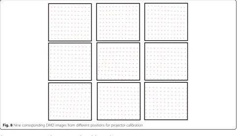
A white plate with 9 × 12 discrete black hollow ring markers was used to calibrate the dual-camera struc-tured light system, as shown in Fig. 3. The calibration plate was randomly placed at nine different orientations in front of the system. At each orientation, vertical and horizontal sinusoidal fringe patterns along with white il-lumination were projected onto the plate surface. Two CCD cameras synchronously captured the fringe pattern images and the texture images under white illumination. The center position of all markers was determined using the ellipse fitting algorithm. The absolute phase of each marker center was calculated from the captured fringe pattern images using the four-step phase-shifting algo-rithm and the optimum three-fringe number selection method. The corresponding point of each marker in the DMD pixel coordinate system was obtained using Eqs. (1) and (2). The nine corresponding DMD images gener-ated by the procedures described in Section “ Theo-ries”(B) are shown in Fig. 8. In addition, a set of calibration images for each camera, the intrinsic parame-ters of both cameras, and the projector were calibrated using the traditional camera calibration method and MATLAB toolbox, as listed in Table 1. fu and fvare the
effective focal lengths of the camera alonguandv direc-tion; u0 and v0 are the principal point along u and v
Y
ME< T ?
Obtain Initial transformation parameters
Find corresponding points and calculate the
transformation parameters
Verify the pairs valid by the five criteria
Obtain fine transformation parameters
N
Fig. 6Skeleton of the variant ICP algorithm
Object
Right camera Left camera
Projector
direction on image coordinate system;k1and k2are the
radial distortion coefficients; p1 and p2 are tangential
distortion coefficients. By selecting images in the same calibration position, the extrinsic parameters could be also calibrated.
The extrinsic parameters of the left pair are
RL¼
−0:5443 0:0251 2:5864
0:1197 −0:9872 −0:1056
0:3224 0:1559 −0:9337
2 4
3 5;
TL¼½−1792:5 209:1 1228T:
In addition, the relationship between the two cameras is
R0¼
0:7781 −0:0042 0:6281
−0:0021 0:9999 0:0092
−0:6282 −0:0086 0:7781
2 4
3 5;
T0¼½−447:0339 −7:0347 184:0076T:
Finally, the extrinsic parameters of the right pair are
RR¼
−2:0484 0:0053 1:6708
0:1616 −0:9868 −0:0161
0:8370 0:1626 −0:5225
2 4
3 5;
TR¼½1073:5 143:1 911T:
Calibration evaluation
To verify the measurement accuracy of the calibrated system, the traditional method [30, 31] is used as com-parison to measure a ‘step artifact’with a set of known variable geometric steps because it is a type of represen-tative of the binocular vision system for 3D reconstruc-tion. All the matched points on one step surface are fitted into a plane. The calculated distance between the neighboring steps is the average value of the distance of all the obtained points on the other step surface to the fitted plane. The actual and measured distance values between the neighboring step and the absolute error are calculated. A comparison experiment between the trad-itional method and the proposed method has been car-ried out, as listed in Table 2. The results show that the accuracy of the proposed calibration method is higher than that of the traditional method. Outliers and Fig. 8Nine corresponding DMD images from different positions for projector calibration
Table 1Calibration results of the intrinsic parametersa
Parameters Value
Left camera Right camera Projector
u0 1226.4696 1282.8621 523.8770
v0 1003.0006 1019.9319 −66.1422
fu 8489.9318 8461.5185 2016.5832
fv 8494.6968 8466.4860 2040.0327
k1 0.0613 0.0839 0.0532
k2 0.05876 0.0352 0.0702
p1 −0.0028 0.0049 −0.0256
p2 −0.0042 0.0009 0.0013
a
invisible data automatically are rejected to improve the measurement accuracy by using five proposed criteria at each iterative step because the measurement accuracy is related to alignment accuracy. Furthermore, the number of the captured images is less than that of the traditional method because the proposed method needs only two texture images to obtain the extrinsic calibration of one camera-projector pair instead of 25 images (a texture image, 12 vertical, and 12 horizontal sinusoidal fringe patterns). The maximum value of the absolute error is 0.041 mm. The experimental results show the proposed calibration method has high accuracy.
Measurement results
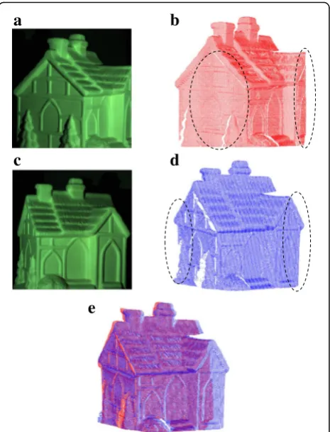
A model house with a freeform surface was measured by the calibrated system. Twelve sinusoidal vertical fringe patterns with the optimum numbers of 100, 99, and 90 were projected onto the house’s surface to calculate the absolute phase. Figure 9aand cshow the texture image obtained by the left camera and right cameras, respect-ively. Three-dimensional cloud data of the model house were obtained using the improved calibration method, as shown in Fig. 9bandd. The profile of the house was not well measured by either camera because of camera occlusions, as illustrated in the region marked by a black ellipse. Figure 9e shows the 3D cloud data after using the proposed calibration method. The geometry mea-sured by the left and right cameras can be compensated mutually to obtain a satisfactory result.
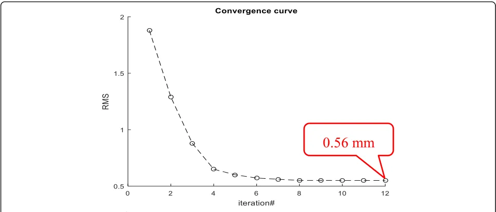
To demonstrate the convergence of the variant ICP al-gorithm, the root mean squared (RMS) at each iteration step is presented. Figure 10 shows the convergence of the variant ICP algorithm on the model house. It is clear that the ICP algorithm is converged monotonically. The final registration error is 0.56 mm.
Discussions
There are three advantages of the proposed calibration method for dual-camera structured light systems: (1) Simultaneity: Both camera images and the projector image, including the vertical fringe images, horizontal fringe images, and texture images, can be obtained for each calibration plate position. Therefore, the intrinsic
and extrinsic parameters of the system can be calibrated simultaneously. (2) Simplification: The proposed tion method can decrease the complexity of the calibra-tion procedures by simplifying the extrinsic calibracalibra-tion of the right pair and the calibration results provide an initial estimate for ICP algorithm. (3) High accuracy: The camera calibration does not influence the projector calibration, and there is no coupling error issue because the camera and the projector are calibrated simultan-eously. Moreover, a modified ICP algorithm was used to compute rigid transformation and correspondence, and to reject outliers and invisible data automatically at each iterative step by using the proposed five criteria.
The measurement accuracy is dependent on the accuracy of matching 3D cloud data sets for each camera-projector in this paper. We have achieved an al-most perfect alignment, however, the variant ICP algo-rithm may converge to an incorrect alignment result in some cases such as an object lacking distinguishing structural feature or under significant camera view changes. In future research, a globally optimal ICP algo-rithm should be developed to avoid the registration Table 2Comparison results of measurement distance between
planes (unit: mm)
Step distance
Traditional method Proposed method
Measured distance
Absolute error
Measured distance
Absolute error
18.212 18.244 0.032 18.237 0.025
13.258 13.211 0.047 13.217 0.041
18.422 18.388 0.034 18.389 0.033
17.603 17.633 0.030 17.629 0.026
a
b
c
e
d
trapping into the local minimum and enhance the meas-urement accuracy of proposed system.
Conclusions
A dual camera-one projector structured light system has been developed to avoid the camera occlusions of a single-camera system. A method to simplify the calibra-tion for dual-camera structured illuminacalibra-tion profiling system is proposed to decrease the number of captured images. For the method, the left camera-projector pair is firstly calibrated. Then, the parameters of both cameras are determined. Subsequently, the relationship between the projector and the right camera is calculated accord-ing to the results from the previous steps. Finally, 3D re-sults from both views are merged by the variant ICP (Iterative Closest Point) algorithm to enlarge the meas-uring range after giving it an initial estimate obtained by the extrinsic parameter calibration results. Five criteria have been proposed to reject outliers and invisible data automatically at each iterative step. Experiments show the performance of the proposed calibration method.
Abbreviations
3D:Three-dimensional; DMD: Digital micro-mirror device; ICP: iterative closest point
Acknowledgements Not applicable.
Funding
The authors would like to thank National Key R&D Program of China (2017YFF0106404); National Natural Science Foundation of China (51675160); Talents Project Training Funds in Hebei Province (A201500503); Innovative and Entrepreneurial Talent Project Supported by Jiangsu Province (2016A377); Joint Doctoral Training Foundation of HEBUT(2017GN0002); European Horizon 2020 through the Marie Sklodowska-Curie Individual Fellowship Scheme (707466-3DRM); the UK’s Engineering and Physical Sciences Research Council (EPSRC) funding of Future Advanced Metrology Hub (EP/P006930/1).
Availability of data and materials Detail data has been provided in this paper.
Authors’contributions
CC and NG conceived and designed the experiment. CC performed the experiments and analyzed the data under the guidance of NG and ZZ. CC and ZZ wrote the paper. All authors read and approved the final manuscript.
Authors’information
Chao Chen is a PhD Candidate in the School of Mechanical Engineering, Hebei University of Technology, China. His current research focuses on three-dimensional optical measurement and machine vision. E-mail Address: [email protected]
Nan Gao is an assistant professor in the School of Mechanical Engineering, Hebei University of Technology, China. His current research directions are optical measurement and spectrum detection. E-mail Address: [email protected] Zonghua Zhang is a full Professor in the School of Mechanical Engineering, Hebei University of Technology, China and a visiting Professor in University of Huddersfield, UK. His research interests include three-dimensional measurement, fringe analysis and computer vision. He has published more than 130 papers, 4 book chapters, 17 patents. E-mail Address: [email protected], [email protected]
Competing interests
The authors declare that they have no competing interests.
Publisher’s Note
Springer Nature remains neutral with regard to jurisdictional claims in published maps and institutional affiliations.
Received: 17 August 2018 Accepted: 18 October 2018
References
1. Ren, Z., Cai, L.: Three-dimensional structure measurement of diamond crowns based on stereo vision. Appl. Opt.48(31), 5917–5932 (2009) 2. Wang, J., Wang, X.J., Liu, F., Gong, Y., Wang, H., Qin, Z.: Modeling of
binocular stereo vision for remote coordinate measurement and fast calibration. Opt. Lasers Eng.54(1), 269–274 (2009)
3. Son, S., Park, H., Lee, K.H.: Automated laser scanning system for reverse engineering and inspection. Int. J. Mach. Tools Manuf.42(8), 889–897 (2002) 4. Briard, P., Saengkaew, S., Wu, X., Meunier-Guttin-Cluzel, S., Chen, L., Cen, K.,
5. Zuo, C., Chen, Q., Gu, G., Feng, S., Feng, F., Li, R., Shen, G.: High-speed three-dimensional shape measurement for dynamic scenes using bi-frequency tripolar pulse-width-modulation fringe projection. Opt. Lasers Eng.51(8), 953–960 (2013)
6. Zuo, C., Huang, L., Zhang, M., Chen, Q., Asundi, A.: Temporal phase unwrapping algorithms for fringe projection profilometry: a comparative review. Opt. Lasers Eng.85, 84–103 (2016)
7. Liu, X.L., Cai, Z.W., Yin, Y.K., Jiang, H., He, D., He, W.Q., Zhang, Z.H., Peng, X.: Calibration of fringe projection profilometry using an inaccurate 2D reference target. Opt. Lasers Eng.89, 131–137 (2016)
8. Zhang, S., Yau, S.T.: Absolute phase-assisted three-dimensional data registration for a dual-camera structured light system. Appl. Opt.47(17), 3134–3142 (2008)
9. Chen, R., Xu, J., Chen, H.P., Su, J.H., Zhang, Z.H., Chen, K.: 2016 accurate calibration method for camera and projector in fringe patterns measurement system. Appl. Opt.55(16), 4293–4300 (2016) 10. Jia, X., Zeng, D.: Model and error analysis for coded structured light
measurement system. Opt. Eng.49(12), 1127–1134 (2010)
11. Zhang, Z.H., Zhang, D., Peng, X.: Performance analysis of a 3D full-field sensor based on fringe projection. Opt. Lasers Eng.42(3), 341–353 (2004) 12. Xu, J., Douet, J., Zhao, J., Song, L., Chen, K.: A simple calibration method for
structured light-based 3D profile measurement. Opt. Laser Technol.48(2), 187–193 (2013)
13. Leandry, I., Breque, C., Valle, V.: Calibration of a structured-light projection system: development to large dimension objects. Opt. Lasers Eng.50(3), 373–379 (2012)
14. Anchini, R., Leo, G.D., Liguori, C., Paolollo, A.: A new calibration procedure for 3-D shape measurement system based on phase-shifting projected fringe profilometry. IEEE Trans. Instrum. Meas.58(5), 1291–1298 (2009) 15. Zhang, Z.H., Ma, H.Y., Guo, T., Zhang, S.X., Chen, J.P.: Simple, flexible
calibration of phase calculation-based three-dimensional imaging system. Opt. Lett.36(7), 1257–1259 (2011)
16. Zhang, Z.H., Huang, S.J., Meng, S.S., Gao, F., Jiang, X.Q.: A simple, flexible and automatic 3D calibration method for a phase calculation-based fringe projection imaging system. Opt. Express.21(10), 12218–12227 (2013) 17. Gao, W., Wang, L., Hu, Z.: Flexible method for structured light system
calibration. Opt. Eng.47(8), 767–781 (2008)
18. Zhang, S., Huang, P.S.: Novel method for structured light system calibration. Opt. Eng.45(8), 083601 (2006)
19. Zhang, Z.Y.: A flexible new technique for camera calibration. IEEE Trans. Pattern Anal.22(11), 1330–1334 (2000)
20. Li, Z.W., Shi, Y.S., Wang, C.J., Wang, Y.Y.: Accurate calibration method for structured light system. Opt. Eng.47(5), 053604 (2008)
21. Chen, X., Xi, J., Jin, Y., Sun, J.: Accurate calibration for camera projector measurement system based on structured light projection. Opt. Lasers Eng. 47(3–4), 310–319 (2009)
22. Chen, R., Xu, J., Zhang, S., Chen, H.P., Guan, Y., Chen, K.: A self-recalibration method based on scale-invariant registration for structured light measurement systems. Opt. Lasers Eng.88, 75–81 (2017) 23. Zhang, S., Yau, S.T.: Three-dimensional shape measurement using a
structured light system with dual cameras. Opt. Eng.47(1), 013604 (2008) 24. Besl, P.J., Mckay, N.D.: A method for registration of 3D shapes. IEEE Trans.
Pattern Anal. Mach. Intell.14(2), 239–256 (1992)
25. Zhang, Z.Y., Tower, C.E., Tower, D.P.: Efficient color fringe projection system for 3-D shape and color using optimum 3-frequency interferometry. Opt. Express.14(14), 64444–64455 (2006)
26. Fitzgibbon, A., Pilu, M., Fisher, R.B.: Direct least square fitting of ellipses. IEEE T. Pattern Anal.21(5), 476–480 (1999)
27. He, D., Liu, X.L., Peng, X., Ding, Y.B., Gao, B.Z.: Eccentricity error identification and compensation for high-accuracy 3D optical measurement. Meas. Sci. Technol.24(7), 075402 (2013)
28. Bouguet, J. Y.: Camera Calibration Toolbox for Matlab.http://www.vision. caltech.edu/bouguetj/calib_doc/
29. Heikkila, J.: Geometric camera calibration using circular control points. IEEE Trans. Pattern Anal. Mach. Intell.22(10), 1066–1077 (2008)
30. Wu, Q., Zhang, B., Huang, L., Wu, Z., Zeng, Z.: Flexible 3D reconstruction method based on phase-matching in multi-sensor system. Opt. Express. 24(7), 7299–7318 (2016)