Vertical Parking - A Case Study of Mahila Baug,
Bhavnagar, Gujarat
Prof. Abhi Mitra Prof. Vijay Parmar
Assistant Professor Assistant Professor
Department of Civil Engineering Department of Civil Engineering Gyanmanjari inst. of Technology, Bhavnagar Gyanmanjari inst. of Technology, Bhavnagar
Prof. Heemika Upadhyay Keval Vaghela
Assistant Professor UG Student
Department of Civil Engineering Department of Civil Engineering Gyanmanjari inst. of Technology, Bhavnagar Gyanmanjari inst. of Technology, Bhavnagar
Harshit Gohel UG Student
Department of Civil Engineering Gyanmanjari inst. of Technology, Bhavnagar
Abstract
We know that with the increase in the population density, this would certainly tend to increase the amount of vehicular population density as well. We are presently taking into notion the facts in respect to the country, INDIA which is by far know to be having known quite a lot in terms of population exploding off decade by decade which is quite a matter of concern as it relates to not only economic stability but also to the social integrity considering the sustainability standards in terms of living a healthy and satisfied life. Due to certain increase in the overall population it tends to increase the vehicular population as discussed above but then the important concern over here is in relation to the management of such a large number. Therefore, proposition of a well-structured car management system is a must in order to manage the large number of cars in as efficient ways as possible. Pertaining to this we propose here a case study upon one of the cities named Bhavnagar in the state of Gujarat, India imitating a way by providing a multi-faceted civil engineering structure which may further prove to be a milestone in terms of parking management systems. The case study is based upon a place named ‘Mahila Baug’ located in the heart of the city in one of the most populated areas considering day to day presence of public. As Bhavnagar as a city is not that well developed in terms of engineering application, the ter m ‘parking management’ is far beyond scope. The area proposed here is densely populated in terms of vehicular density as well and not a lot of well managed space is available to manage the same. We propose a structure which not only will improve the scope of enabling engineering application in the city but will also promise to prove as one of the most efficient systems when it comes to either construction of the structure or water management and energy efficiency or parking management. The overall dimensions of the area are 165.71X 99.42X171.34X98.74 M which is more than sufficient for building the structure and accommodating with all the following modernized engineering application that we tend to propose.
Keywords:Parking management, engineering applications, energy efficiency
I. INTRODUCTION
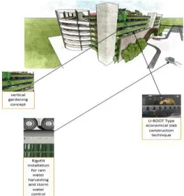
The structure is a G+5 building comprising of parking slots throughout the structure with a proposed restaurant on the top for commercial purposes. Moreover, the building consists of some diversified applications in terms of controlling carbon dioxide emissions, water management systems and also energy efficiency some of which in form of distinctive images are shown below: -
Fig. 1.2: Front View of the Structure (Proposed)
Table - 1.1
Important Specification of the structure Important Specifications for the Structure (Proposed)
Overall Area dimensions 165X99.42X171.34X98.74 M
Ground Floor vehicle
accommodation 478 Two Wheelers
Floor 1 to 5 vehicle accommodation 104 Four Wheelers Per Floor Area of Implementation (suggested) Mahila Baug, Bhavnagar, Gujarat
No. Of Floors G+5 Floors
Other Specifications
1) Restaurant type implementation at the top floor. 2) Vertical gardening concept.
3) Rain water harvesting System using Rigofill technology.
4) Usage of piezoelectric crystals in the pathway for electricity storage and overall compensation. 5) U-boot Concept of slab construction.
II. THE CONCEPT OF VERTICAL GARDENING
The concept renders to presentation of gardens or sticking grass layers at the front part of the building adding to aesthetics and architectural view points of the structure. The structure would be present in a place where the levels of pollution tends to be quite high due to the place being densely populated out of vehicle movement, coupling the structure along with greenery will certainly tend to help upon controlling carbon dioxide getting emitted in the environment near by the structure as absorption of carbon dioxide gas comes up as the very property for green plants and trees. Here maintaining the greenery may become a bit of a problem as it requires quite a lot of maintenance and also a lot of water to keep itself activated for performing all the desired activities. Now this problem over here is taken care of by the concept rain water harvesting and storm water storage in the form of Rigofill installation the advantages of which are unmatched and qualifies really well upon helping the gardens keeping themselves greener (the concept would be explained further on!). Also presence of greenery would also further help control the temperature levels as the gas responsible for causing the temperature rise majorly which is carbon dioxide tends to get absorbed by them.
Fig. 1.4: Presentation of Grass Bands for Horizontal Gardening Purposes (Proposed)
Fig. 1.5: Hot air to Cool air conversion
III. THE CONCEPT OF RIGOFILL INSTALLATION
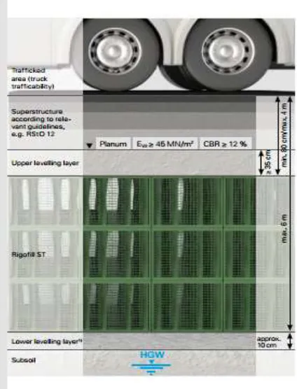
Fig. 1.6: Connection representation for Rigofill
The specialty of such connections as can be seen is that it does not occupy a lot of area as such providing most of the area for water storage purpose applications apart from that if we need to talk about the durability then the structure is made out of high quality polymers which proves to very durable in the long run. The structure is capable of resisting higher amounts of load proving to have presented commendable bearing strength. The structure can easily withstand heavier loads, in respect to the application in this case study the application will mostly happen in the sub soil beneath the pathway/roadway which would entertain a lot of vehicular movement which needs to be well resisted in terms of sustainability of the overall combination of system proposed.
Fig. 1.7: Bearing of load by Rigofill
Taking upon the analysis of overall performance it is of high caliber as a full stack of Rigofill could easily fill up 400 plus liters of water at a go at places with high level of ground water level it is 200 plus liters the overall storage volume accounts to be about 96% of the total space available in the columns. Storage of such high amount of water could be helpful in a lot of ways addressing to some would be like
1) Maintenance of horizontal gardens.
2) Could be used for washing and cleaning purposes of the parking space. 3) Could be put up for use for urinal purposes.
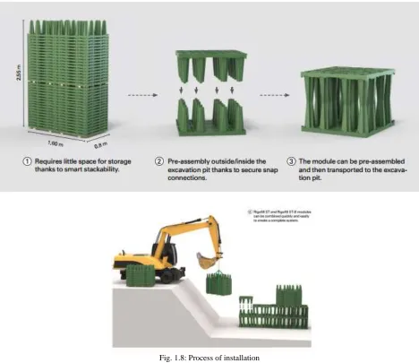
assembly taking up the least time also the space required is quite less as compared to drainage pits proving to be on a lot more on the advantage side. The transportation again is very easy as the parts are fairly light weight and easy to transfer from one place to another.
Fig. 1.8: Process of installation
The Rigofill are designed in a way where it is very much visible that quality is given the top most priority in terms of build quality also providing adequate space when it comes to future quality inspection and assessment the design is in a way providing adequate spaces for movement after the installation of the structure making it 100% inspect able.
IV. THE U-BOOT CONCEPT OF SLAB MAKING
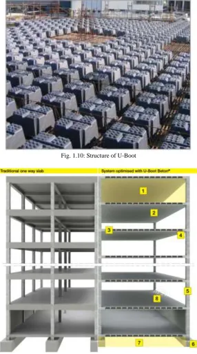
Nature has given us a lot of things which we cannot get really tend to forget therefore it becomes our duty to give back at least something back to the nature. The U-Boots are recycled material made out of polypropylene that have proven to be of great help in reducing the overall number of columns and beams making the construction of the structure very economical in nature. The use U-Boot technology renders to least use of concrete while casting of slab, takes up most of the load and requires the least amount transfer therefore limiting the number of beams and columns and also reducing the overall load transfer to the foundation decreasing the rate failure by a bigger margin. The shape of U-Boots is in form of empty boxes which are sandwiched between two layers of reinforcement and some amount of concrete in order to act as a bond between all the elements contributing to the making of slab. As the load transfer to the foundation is quite less over here the overall depth of foundation could easily be reduced saving up a lot upon excavation and foundation setting up cost also the fact that the usage of column is least the structure leads to possess more space for architectural experimentation. Over here as there is not a lot of scope for architectural aesthetics within the structure the least number of columns could prove to be of use in accommodating greater number of vehicles in the building.
Fig. 1.11: Advantage analysis (traditional & U-Boot system)
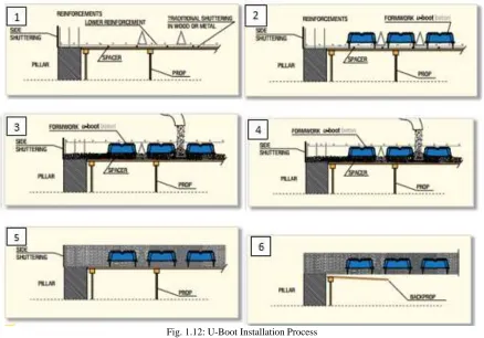
Coming again on the point of installation into the slabs is again fairly easy process as it does not require any special skills to place the U-Boot within the slabs. Firstly, the initial grid of reinforcement and wooden formwork is made up as of traditional technique of slab casting after which U-Boots which are available in varying sizes and could be installed as per requirement after which concrete is poured and left aside for its journey of curing phase. After which the final look of the slab tends to remain pretty much traditional but then the characteristics are far different as explained above the following pictures would provide a better view upon the above written process in a much clear way.
Fig. 1.12: U-Boot Installation Process
V. THE USAGE OF PIEZOELECTRIC CRYSTALS BLOCKS IN PATHWAYS
VI. THE RESTAURANT
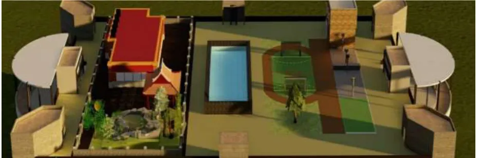
The top portion of the structure remains to be empty which could therefore be used for commercialized purposes in form of building a restaurant combined with swimming pool for relaxation purposes. The above stated idea could help in generating economical alliances and also prove to be a meaningful utilization of the space available.
Fig. 1.10: Proposed restaurant structure for utilization of free space available at the top (Proposed)
VII. CONCLUSION
The construction of this building turns out to be on the very balanced side as RCC part compensates with a cheaper rate of construction limiting the number of beams & columns and reducing the depth of foundation via using U-Boot system. Again installation of Rigofill may prove out to be a bit on the costlier side but then the maintenance and quality control costs are quite low and also the performance is very efficient and saves a lot of money when it comes to investing alliances upon obtaining water. Moreover, easy to transport and installation techniques adds a lot towards the brighter side of the above listed whole process, making of a restaurant in combination would help reach out breakeven points quite early in business helping the owner with further advancements of the structure. All in all, the whole process described in the form of case stud could be well implemented in terms of practicality as all the important techniques are reachable and implementable in real time making it worth taking a go at building a structure like this!
REFERENCES
[1] Sharma Piyush, Vertical Gardens- An Innovative Element OF Green Building Technology. Available.
http://iec.edu.in/wp-content/uploads/2016/01/7_Piyush-Sharma_VERTICAL-GARDENS-pp.42-48.pdf
[2] U-boot beton, daliform group. Available http:// www.daliform.com
[3] Rigofill ST and Rigofill ST-B, Fränkische Rohrwerke. Available