Article
Grid Synchronization of Seven-Phase Wind Electric
Generator Using d-q PLL
Kalaivani Chandramohan 1, Sanjeevikumar Padmanaban 2,*, Rajambal Kalyanasundaram 1, Mahajan Sagar Bhaskar 2 and Lucian Mihet-Popa 3
1 Department of Electrical and Electronics Engineering, Pondicherry Engineering College, Kalapet, Puducherry, India; [email protected] (K.C.); [email protected] (R.K.)
2 Department of Electrical and Electronics Engineering, University of Johannesburg, Auckland Park, South Africa; [email protected]
3 Faculty of Engineering, Østfold University College, Kobberslagerstredet 5, 1671 Kråkeroy; Building: S 316, Norway; [email protected]
* Correspondence: [email protected]; Tel.: +27-79-219-9845
Abstract: The evolving multiphase induction generators (MPIG) with more than three phases are receiving prominence in high power generation systems. This paper aims at the development of a comprehensive model of the wind turbine driven seven-phase induction generator (7PIG) along with necessary the power electronic converters and controller for grid interface. The dynamic model of the system is developed in Maltlab/Simulink. Synchronous reference frame phase-locked loop (SRFPLL) system is incorporated for grid synchronization. The modeling aspects are detailed and the system response is observed for various wind velocities. The effectiveness of seven phase induction generator is demonstrated with the fault tolerant capability and high output power with reduced phase current when compared to conventional 3-phase wind generation scheme. The response of the PLL is analyzed and the results are presented.
Keywords: multi-phase; synchronous frame; induction generator; PWM inverter; seven phase rectifier; PLL; grid
1. Introduction
Electric power generation by exploring the use of renewable energy source is viable solution for reducing the dependency of fast depleting fossil fuels and to fit into the environmental conditions. Among all existing non-conventional sources wind has latent qualities that can be utilized to meet the heaping energy demand [1]. Self-excited induction generators (SEIGs) are usually deployed for wind energy conversion system in standalone applications with its inherent characteristics as mentioned in [2-3]. Later they also operated in grid connected mode for distributed power generation in hybrid micro grids [4]. However they are suitable for low and medium power applications [3]. MPIG with more than three phases is a potential contender which combines the advantages of MPIG with SEIG technologies yielding an efficient, reliable and fault tolerant machine which finds diverse application. [5-8]. Multiphase systems can be employed for different applications, such as offshore energy harvesting, electrical vehicles, electric ship propulsion and aircrafts. The earlier proposed research works brief the supremacy of multiphase machines to obtain a better reliable performance [9-14].
As a consequence, MPIG research has evoked interest among researchers in the recent past which has culminated in to gradual but steady progress in this field. However, available literature suggests finite modeling approaches implemented for MPIG analysis.
The d-q model of six phase induction generator with dual stator and single rotor is presented [15]. The performance of six phase dual stator induction generator is investigated [16]. Dynamic analysis of six phase induction generator for standalone wind power generation [17], steady state performance analysis of the machine and its experimental validation [18-19] has been carried out.
The grid integration of wind electric generator (WEG) is a critical aspect in the planning of wind power generation system. The variation in production and higher intermittency of wind generation makes it difficult for grid integration. Hence it is necessary to provide appropriate synchronization techniques such that the system maintains constant frequency and voltage to ensure stable and reliable operation of grid [20]. A good synchronization method must detect the frequency and phase angle variations proficiently in order to reduce the harmonics and disturbances for safe operation of the grid. Further simple implementation and cost decides the reliability of synchronization scheme [21]. The power transfer between Distributed generation and grid is enhanced by good synchronization method. Earlier known zero crossing detectors have adverse power quality issues during weak grid. Nowadays PLL is one of the generally used techniques and it controls Distributed power generation system and other applications. Several types of PLL are analyzed in [22-23]. This paper aspires at developing a PLL based grid connected seven phase WEG where PLL enables the frequency and voltage synthesis.
A d-q model of seven phase induction generator (7PIG) with stator windings phase shifted by 51.420 is developed. Simulation is carried out to study the performance under varying wind velocities. The voltage build up process is shown. The generator voltage, current and power output is presented under varying load conditions. The reliability of the machine under fault condition is examined with one or two phases open. The results are compared with the three phase generator. The power electronic interface namely the seven phase rectifier, boost converter and three phase NPC inverter are simulated for varying modulation indices and results are explored. The SRF PLL is designed to track phase angle and frequency. The response of PLL is analyzed various grid conditions like unbalanced grid voltages, voltage sag, line to line (LL) fault and line to line ground fault (LLG)and the results are explored.
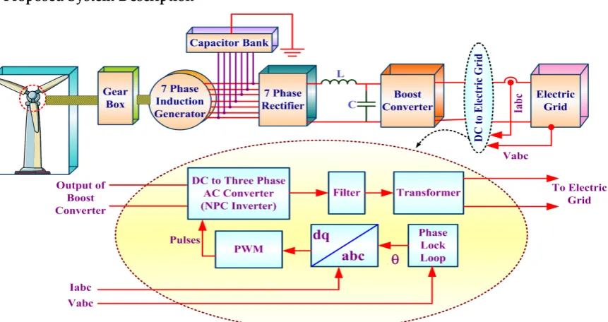
2. Proposed System Description
Figure 1. Seven Phase Grid connected Wind electric Generator
3. Modeling of System Components
The mathematical modeling of the seven phase wind generator components namely wind turbine, seven phase induction generator, seven phase rectifier and three phase inverter and PLL are discussed in the following sections.
3.1. Wind Turbine
The following equation defines the power output of the wind turbine 3
0.5 ( ) tur ACp Vw
ρ = ρ λ (1)
1 16.5 1
116
0.4
5
0.5?
Pe
C
β
λλ
−
−
−
=
(2)tur w
R
V
ω
λ
=
(3)(
)
1
3
1
1
0.035
0.089
(
1)
λ
λ
β
=
−
+
+
(4) Where, turρ : Air density (kg/m3); Vw- wind velocity (m/s); R - Radius of the wind turbine rotor (m) ; A - Area
swept out by the turbine blades (m2) ; Cp: power coefficient defined by equation (2); λ - Tip speed ratio given by equation (3)
ω
tur: angular rotor speed of the turbine(rad/sec);β
: The blade pitch angle (deg.)3.2. 7PIG Model
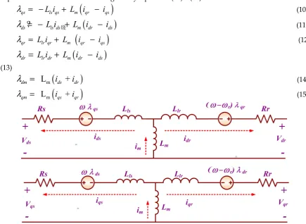
A 7ɸIG has seven stator windings sinusoidally distributed with phase displacement of 51.4º (3600/7) and the rotor is short circuited for squirrel cage induction machine. The7ɸ induction machine operating as generator is represented as a two phase equivalent circuit. The ds-qs represent stator direct and quadrature axes and dr-qr represents rotor direct and quadrature axes. The transformation of seven phase stationary reference frame variables to two phase stationary reference frame is given by equation (5). Assumptions made in modeling 7ɸIG are same as given in [7] and [26]. The modeling 7ɸIG is carried out using d-q equivalent circuit shown if Figure 2 [24-26].
1
cos
cos 2
cos 3
.
cos
0
sin
sin 2
sin 3
.
sin
1
cos 2
cos 4
cos 6
. cos 2
.
0
sin 2
sin 4
sin 6
. sin 2
.
.
.
.
.
.
.
.
1
1
1
1
1
.
2
2
2
2
2
s a q s b d s c x s d y s n o
n
V
V
n
V
V
n
V
V
X
n
V
V
V
V
α
α
α
α
α
α
α
α
α
α
α
α
α
α
α
α
=
(5)Where α=2π/n; n=no of phases; s, r represent stator and rotor quantities; d-q represents direct and quadrature axis.
Equations (5) and (6) defines the stator side voltages
qs s qs ds qs
V = −R i +
ωλ
+ pλ
(6)ds s ds qs ds
(
)
qr r qr r dr qr
V
=
R i
+
ω ω λ
−
+
p
λ
(8)(
)
dr r dr r qr dr
V
=
R i
−
ω ω λ
−
+
p
λ
(9) The voltage equations for dynamic performance analysis under balanced condition are represented in stationary reference frame (ω =0). The rotor side voltages Vqr and Vdr are zero for squirrel cage induction generators. The rotor side quantities are referred to stator. The flux linkage expression as function of current is given by equations (10) – (15).(
)
ls qs m
qs
L i
L i
qri
qsλ
= −
+
−
(10)(
)
牋
?
ds
L i
ls dsL i
m dri
dsλ
= −
+
−
(11)(
)
qr
L i
lr qrL
mi
qri
qsλ
=
+
−
(12)(
)
dr
L i
lrdrL i
m dri
dsλ
=
+
−
(13)
(
)
m
L
+
dm
i
dsi
drλ
=
(14)(
)
m
L
+
qm
i
qsi
qrλ
=
(15)Figure 2. d-q-axis equivalent circuit of 7ɸIG
The leakage inductance of stator and rotor are assumed constant. The degree of magnetic saturation decides magnetizing inductance Lm and it is a non-linear function of magnetizing current which is given by the following equation
(
)
(
)
m
2 2
I
=
i
qr+
i
qs+
i
dr+
i
ds (16)The non-linear piecewise relationship between the magnetizing inductance and current (Lm,im) is given by
(
)
(
)
(
)
(
)
m 0.012726,0 25.9441.94597 / 117.6 , 25.944 51.512
L 1.79031/ 61.2 ,52.512 73.8
1.41566 / 46.296 ,73.8 85.872 2.67838 / 31.608 , 85.872
m m m m m m m m m i i i i i i i i i
≤ <
+ ≤ <
= + ≤ <
+ ≤ <
+ ≥
(17)
The developed electromagnetic torque of the 7ɸIG is defined by
(
)
7
2
2
g m qs d r ds qr
P
T
L
i i
i i
= −
−
(18)Negative (-ve) Sign indicates generation action.
r lr m
s ls m
L
=
L
+
L
(20)3.3. Modeling of shunt capacitor and load
The modeling equations of voltage and current of the excitation capacitor and load in d-q axis is given by equations (21) - (26)
1
qs cqs ds
V
i
V
C
ω
ρ
−
=
(21)1
ds cds qs
V
i
V
C
ω
ρ
+
=
(22)cqs qs Rqs
i = i − i (23)
cd s ds Rds
i
=
i
−
i
(24)qs Rqs
V
i
R
=
(25)s Rds d
V
i
R
=
(26)The 7ɸ voltages are transformed to 2ɸ using equation (27).
cos
sin
cos(
)
sin(
)
cos(
2 )
sin(
2 )
cos(
3 )
sin(
3 )
cos(
4 )
sin(
4 )
cos(
5 )
sin(
5 )
cos(
6 )
sin(
6 )
a qs e ds e
b qs e ds e
c qs e ds e
d qs e ds e
e qs e ds e
f qs e ds e
g qs e ds e
V
V
V
V
V
V
V
V
V
V
V
V
V
V
V
V
V
V
V
V
V
θ
θ
θ α
θ α
θ
α
θ
α
θ
α
θ
α
θ
α
θ
α
θ
α
θ
α
θ
α
θ
α
=
+
=
−
+
−
=
−
+
−
=
−
+
−
=
−
+
−
=
−
+
−
=
−
+
−
(27)4. Dc Link Converter
The power electronics based interface system namely the DC link converter involves a seven phase rectifier, three phase inverter and a dc-dc boost converter. The uncontrolled seven phase rectifier converts the seven phase ac output of the generator to dc and is boosted by boost converter.
4.1. Seven phase Diode bridge rectifier
A variable magnitude, variable frequency voltage at the seven phase induction generator terminal is converted to DC using a seven-phase diode bridge rectifier [30].The voltage Vrec at the output is given by equation (28) in terms of the peak phase voltage Vds of the generator. The LC filter reduces output voltage ripple of the seven phase rectifier.
/2
3 /14
1
1.949
sin(
/14) ( )
(2 /14)
rec ds
V
πV
t
d t
π
ω π
ω
π
=
+
(28)1.932
rec ds
V
=
V
(29)
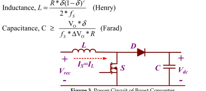
4.2. DC-DC Boost Converter
A DC-DC boost converter steps up the input voltage depending upon duty ratio, inductor and capacitor values [25]. The output voltage of the boost converter is given by
1
rec dcV
V
δ
=
Where,
Vrec - Input voltage from the seven phase rectifier and δ-Duty cycle of the switch. The inductance and capacitance are designed using the following equations (31) and (32).
2
* (1
)
Inductance,
(Henry)
2*
SR
L
f
δ
−
δ
=
(31)O
O
V *
Capacitance, C
(Farad)
* V *
S
f
R
δ
≥
Δ
(32)Figure 3. Power Circuit of Boost Converter.
4.3. Three Level Neutral Point Clamped Inverter
The DC input is given to this inverter from the DC/DC converter and three phase three level output obtained is given to the grid through a step-up transformer. The modulation index of the reference signal is varied to control the output voltage of the inverter and is given by relation by
a
Modulation Index, m
2
m dc
V
V
=
(33)Where,
Vm - Peak value of the Phase voltage (V)
Vdc - Input DC voltage / Output of the Boost converter
5. Grid Interface using PLL
Figure 4. Basic Phase Locked Loop (PLL) Structure.
The effective power transfer between grid and the source can be realized by the efficient synchronization technique. The most familiar method is tracking of phase angle using PLL which synchronizes voltage and frequency of given reference and output signal .A phase detector, loop filter and voltage controlled oscillator (VCO) together makes a basic PLL system wherein phase detector generates an error signal by comparing the reference and output signal. The harmonics of error signal is eliminated by loop filter. Depending on output of loop filter VCO generates the output signal. The basic structure of PLL circuit is as shown in Figure 4. Linear PLL is usually used in single phase system whereas a three phase system employs a SRF PLL or otherwise d-q PLL.
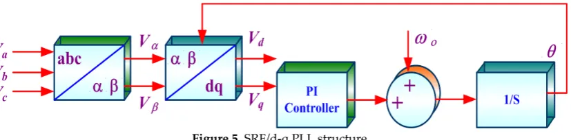
5.1. Synchronous Reference Frame (SRF/d-q ) PLL
reference making the q-axis component zero in steady state. The d-axis will be the voltage amplitude during steady state condition.
Figure 5. SRF/d-q PLL structure
The d- and q-axis component is defined by the following equation under balanced condition
ˆ
ˆ
ˆ
cos sin
cos
cos(
)
ˆ
ˆ
sin
ˆ
sin cos
sin(
)
d q
V
U
U
V
U
U
θ
θ
θ
θ θ
θ
θ
θ
θ θ
−
=
=
−
−
(34) WhereU,
θ
– amplitude and phase of input signalˆ
θ
- PLL outputd, are the d and q-axis component
The phase is denoted by q-axis and amplitude in steady state denoted by d-axis error. The generalized voltage vector under unbalance utility conditions (without voltage harmonics) is represented by
0
V
= + +
V
+V
−V
(35) The positive, negative and zero sequence components are represented by subscripts +, - and 0. The αβ component using Clarke’s transformation is given by/ a abc b c
V
V
V
V
T
V
V
V
α αβγ β αβ γ
=
=
(36) /-1
-1
1
2
2
2
3
3
0
3
2
2
1
1
1
2
2
2
abc
T
αβ
=
(37)The zero-sequence component is neglected as it is on the γ-axis. The expression of the voltage vector on the αβ-plane is:
/
cos
cos
(
)
sin
sin
abcU
U
V
T
V
V
U
U
αβ αβθ
θ
θ
θ
+ + − − + − + + − −+
=
+
=
+
(38)The αβ frame is transformed to d-q frame using parks transformation.
/
ˆ
ˆ
cos(
)
cos(
)
cos(2 )
=
ˆ
ˆ
sin(2 )
sin(
)
sin(
)
dq dq
U
U
U
U
t
V
T
V
U
U
t
U
U
αβ αβθ θ
θ θ
ω
ω
θ θ
θ θ
+ + − − + − + − + + − −
− +
−
+
=
=
−
− +
−
(39)/
ˆ
ˆ
cos sin
ˆ
ˆ
sin cos
dq
T
αβθ
θ
θ
θ
=
−
is the angular frequency of voltage vector and
θ θ θ ω
ˆ
= = =
+ −t
6. Simulation Result
The modeling equations of the various system components are simulated with the parameters given in APPENDIX-I. The individual component models are analyzed and integrated to study the performance of the seven phase wind electric generator. The simulation results are discussed in the following sections.
6.1. Wind Turbine
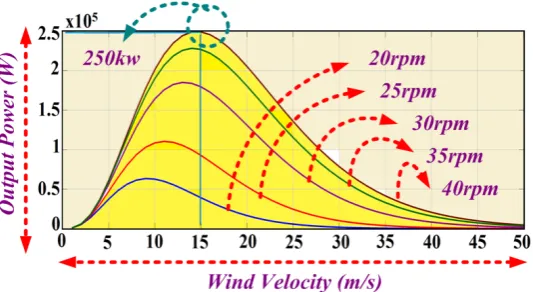
A 250kW wind turbine is simulated using the equations (1) – (4) for various wind velocities and rotational speeds. Figure 6 shows the power curves of the wind turbine at various wind speeds. The rated power of 250kW is achieved at rated wind velocity of 15m/s and 40 rpm as shown in figure 6. The wind turbine produces maximum power at various rotational speeds for different wind velocities.
Figure 6. Wind Turbine Power Output Vs Wind Velocity
6.2. Seven Phase Induction Generator
The mathematical equations represented by the equations (5)-(27) is used to develop a mathematical model of 7ɸ induction generator from the d-q equivalent circuit shown in Fig.2. The performance of 7ɸIGis investigated under various operating conditions.
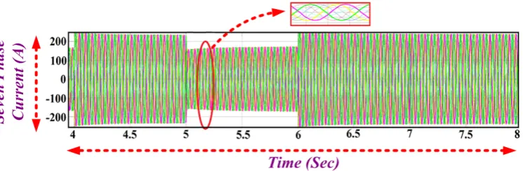
The rated speed of 1018 rpm with the excitation capacitance of 2332 µF is given as input to the generator and the voltage and current of the 7ɸIG are obtained at no load and presented in Figure 7. The self-excitation process begins at time t=0, the stator voltage builds and the steady state value of 419V (peak) and current of about 165Ais reached at t=2.2secs with the phases mutually displaced by 51.40 (2π/n).
(a)
(b)
(c)
(d)
(a)
(b)
(c)
Figure 8. Generated Line Voltage of 7ɸIG Adjacent Side & Non Adjacent Side (a) Vab (b)Vac (c)Vad
Figure 9. This fault current of 7ɸIG with one phase open (Vc).
6.3. Fault tolerant operation of MPIG
Figure 10. This fault current of 7ɸIG with one phase open (Vc).
(a)
(b)
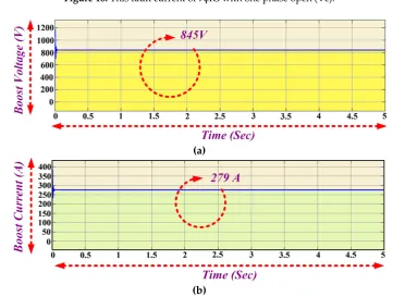
Figure 11.(a) boost voltage (b) Boost current
6.4. DC Link Converter
The generated seven phase ac output is fed input to the seven phase rectifier. The rectified dc output is shown in figure 12. The peak value of phase voltage 386 is fed to rectifier which gives converter 645 volts and a current of 376 A the output of rectifier is fed as input to the converter. The output voltage is found to be 845 V and current of about 279A as shown in figure 10 (a) and (b).
6.5. Grid Integration
The grid tied inverter is the power electronic converter that converts the DC into AC but with the synchronizing qualifications. It is basically used in the applications of the integration of renewable energy to the utility line. The magnitude and phase of the inverter voltage should be as same as that of the grid and its output frequency should be equal to the grid frequency for grid synchronization.
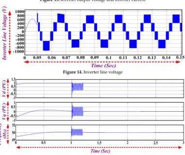
Figure 12. Vdc and modulation index
Figure 13. Inverter output voltage and inverter current
Figure 14. Inverter line voltage
The d and q axis voltage of d-q PLL and frequency tracking is shown in figure 14. The voltage and current drawn by load connected at point of common coupling is shown in figure 15 (a) and (b). The grid voltage and current is given by figure 16. The power injected into the grid is about 196 kW which is as shown in figure 17.
Figure 16. Load Voltage and Load Current
Figure 17. Grid Voltage (Vgrid) and Grid Current (Igrid)
Figure 18. Power injected into the Grid
6.6. SRF PLL performance under various grid Conditions
(a)
(b)
Figure 19. (a) Frequency and Phase Angle variation during Line to Line fault (b) q-axis and d- axis voltage magnitude during Line to Line fault
During unbalanced grid voltages, the sinusoidal nature in q axis voltage affects the output of PI controller and generates sinusoidal error signal and hence sinusoidal angular frequency this is shown in figure 20 (a) and figure 20(b) which is similar to line to line fault. SRF PLL performance during voltage sag is shown in figure 21(a) and figure 21(b). Voltage sag condition occurs in grid such that magnitude of all phase voltages are equal and their magnitudes are 50% of nominal voltage. It is noticed that it doesn't cause any oscillations in the frequency and the q-d axis voltages. Balanced voltage sag doesn't affect PLL tracking. However, sudden change in magnitude cause the dip in estimated frequency of SRF PLL and later SRF PLL tracks the phase angle of the grid voltages.
(b)
Figure 20. (a) Frequency and Phase Angle variation during LLG fault (b) Description of what is contained in the second panel. Figures should be placed in the main text near to the first time they
are cited. A caption on a single line should be centered.
(a)
(b)
(a)
(b)
Figure 22. (a) Frequency and Phase detection variation during voltage sag (b) q-axis and d-axis voltage magnitude during voltage sag.
5. Conclusions
In this article, a comprehensive model of wind driven 7ɸIG in grid connected mode is developed using the two axis d-q equivalent circuit. Seven phase wind electric generator is integrated using the individual system components and the performance of seven phase wind electric generator is analyzed for varying wind velocities. Synchronous reference frame PLL incorporated for grid interface is simulated and analyzed. The enhanced performance 7PIGis evaluated through fault tolerant capability and high output power with reduced current per phase when compared with three phase. The performance SRF-PLL incorporated in grid connected seven phase wind electric generator is analyzed for various operating grid conditions. The use of multiphase machines along with PLL synchronization of grid increases the reliability of the WEG due to the possibility of achieving post-fault disturbance free operation provided by seven phase machine more over constant voltage and frequency operation enabled by d-q PLL.
Appendix A
Wind Turbine 7PIG
Rated power 250kW Rated power 210 kW
No. of blades 3 Rated voltage 240V
Rated speed 40rpm Rated current 240A
Rotor Diameter 29.8m Rated frequency 50Hz
Air density 1.2kg/m3 Rated power factor 0.82
Blade pitch angle -1.1 Rated speed 1018rpm
Cut-in wind speed 3m/s Stator resistance 0.12 ohms
Cut-out wind speed 25m/s Stator leakage inductance 0.017197mH
Rated wind speed 15m/s Rotor resistance referred to stator 0.0047ohms Equivalent inertia 1542 kg-m2 Rotor leakage inductance referred
to stator
0.015605mH
References
1. Yaramasu, V,; Bin, Wu; Sen, P, C; and et.al. High-power wind energy con-version system: state-of-the-art and emerging technologies,IEEE Proc., vol.103, no.5, pp.740-788, 2015.
2. G, K, Singh. Self-Excited Inducation Generator Research – a survey, journal on Electric power systems research, Elsevier 69; 107-114,
3. R, C, Bansal. Three phase self-excited induction generator-an overview, IEEE Transactions On Energy Conversion, Vol. 20, No. 2, June 2005.
4. Thomsen, B;’ Guerrero, J and Thogersen, P. Faroe islands wind-powered space heating microgrid using self-excited 220-kW induction generator. IEEE Transaction Sustainable Energy, vol. 5, 1361–1366, 2014.
5. Khan, M, F and et al. Modeling, implementation and analysis of a high (six) phase self-excited induction generator. JESIT, http://dx.doi.org/10.1016/j.jesit.2016.12.016 , (2017).
6. Levi. Analysis of double stator induction machine used for a variable speed constant frequency small scale hydro/wind electric generator. Electric Power System Research; vol. 11, 1986.
7. E, Levi; R, Bojoi; F, Profumo; H, A, Toliyat and S, Williamson. Multiphase induction motor drives – a technology status review. IET Electronics Power Application, vol.1, pp. 489–516, 2007.
8. G, K, Singh. Multiphase Induction Machine drive research. Elsevier Journal, Electric Power System Research, Vol. 61, pp. 139-147, 2002.
9. Jones M and Levi E. A literature survey of state-of-the-art in multi-phase ac drives. In Proc. 36th Univ. Power Eng. Conf. UPEC; p p. 505–10, Stafford, 2002,
10. Apsley, J, M,; Williamson, S,; Simth, A, and Barnes, M. Induction machine performance as a function of phase number. IEE Proc. Electron. Power Appl., Vol. 153, No. 6, pp.898-904, 2006 11. Apsley, J and Williamson, S. Analysis of multiphase induction machines with winding faults.
IEEE Trans. Ind. Appl., Vol. 42, No. 2, pp. 465-472, 2006.
12. T, Wang; F, Fang; X, Wu; and X, Jiang. Novel Filter for Stator Harmonic Currents Reduction in Six-Step Converter Fed Multiphase Induction Motor Drives. IEEE Transactions On Power Electronics, Vol. 28, No. 1, 2013
13. Ayman S; Abdel-Khalik and Shehab Ahmed. Performance Evaluation of a Five-Phase Modular Winding Induction Machine. IEEE Transactions on Industrial Electronics, vol. 59, no. 6, june 2012.
14. Ayman S; Abdel-Khalik and M, Masoud. Effect of Current Harmonic Injection on Constant Rotor Volume Multiphase Induction Machine Stators: A Comparative Study. IEEE Transactions on Industry Applications, Vol. 48, No. 6, November/December 2012.
15. Singh G, K; Yadav KB and Saini RP. Modeling and analysis of multi-phase (six phase) self-excited induction generator. In: Proc. IEEE Conf. The Eighth International Conference on Electrical Machines And Systems, ICEMS’05, vol. 3; 2005.
16. Singh G, K; Yadav KB and Saini RP. Analysis of a saturated multi-phase (six-phase) self-excited induction generator. International Journal Emerging Electr. Power System Vol.7, 2006.
17. Singh G, K. Modeling and experimental analysis of a self-excited six-phase induction generator for stand-alone renewable energy generation. Internation Journal Renew Energy, Vol.33, 2008. 18. Singh G, K; Yadav K, B and Saini R,P. Capacitive self-excitation in six-phase induction
19. Singh G,K. Steady-state performance analysis of six-phase self-excited induction generator for renewable energy generation. In: Proc. the 11th Int. Conf. on Electrical Machines And Systems, ICEMS, 2008
20. Mittal, R; Sandhu, K, S and Jain, D,K. An overview of some important issues related to wind energy conversion system (WECS). Int. J. Environ. Sci. Dev. vol.1 , Oct 2004.
21. F, Blaabjerg; M, Liserre; and K, Ma. Power Electronics Converters for Wind Turbine Systems. IEEE Transactions on Industry Applications, vol.48(2), 2012.
22. L, R, Limongi; R, Bojoi; C, Pica; F, Profumo and A, Tenconi. Analysis and Comparison of Phase Locked Loop Techniques for Grid Utility Applications. Proc. IEEE Power Conversion Conf. PCC, pp. 674-681, 2007.
23. M, Karimi-Ghartemani and M, Iravani. A method for synchronization of power electronic converters in polluted and variable-frequency environments. IEEE Trans. Power System, vol.19, no. 3, pp. 1263–1270, Aug. 2004.
24. P, C, Krause. Analysis of Electric Machinery and Drive systems. Wiley IEEE Press, 2013 25. Bimal, K, Bose. Modern Power Electronics and AC Drives. Prentice Hall, USA, 2002
26. Renukadevi, G, and Rajambal, K. Generalized model of multi-phase induction motor drive using Matlab/Simulink. Int. IEEE PES Conf. Innovative Smart Grid Technologies, Kerala, India, 2011
27. Renukadevi, G, and Rajambal, K,; Novel carrier-based PWM technique for n-phase VSI. International Journal Energy Technology, vol.1(3), pp. 1-9, 2011.
28. G, Renukadevi and K,Rajambal. Comparison of different PWM schemes for n –phase VSI. In Proc. International Conference on Advances In Engineering, Science And Management pp.559-564, March 2012.
29. Renukadevi, G,; and K, Rajambal. Field programmable gate array implementation of space-vector pulse-width modulation technique for five-phase voltage source inverter. IET Power Electronics ,Vol.7 (2), pp.376-389, 2014.
30. M, Masoud. Five-phase Uncontrolled Line Commutated Rectifier: AC Side Compensation using Shunt Active Power Filter. Proceedings of the 8th IEEE GCC Conference and Exhibition, Oman, February2015
Acknowledgments: No funding resources.
Author Contributions: Kalaivani Chandramohan, Sanjeevikumar Padmanaban, and Rajambal Kalyanasundaram, has developed the concept of the research proposed and developed the numerical background; Mahajan Sagar Bhaskar involved in the implementation of numerical simulation along with other authors for its depiction in quality of the work with predicted output results. Lucian Mihet-Popa has contributed his experience in AC drives and Wind Energy Conversion for further development and verification of theoretical concepts. All authors involved in articulating the paper work in its current form in each part their contribution to research investigation.