Fuel Gas Network Synthesis Using Block
Superstructure
Jianping Li, Salih Emre Demirel and M. M. Faruque Hasan*
Artie McFerrin Department of Chemical Engineering, Texas A&M University, College Station, TX 77843-3122, USA.; [email protected]; [email protected]
* Correspondence: [email protected]; Tel.: +1-979-862-1449
Abstract: Fuel gas network (FGN) synthesis is a systematic method for reducing fresh fuel
1
consumption in a chemical plant. In this work, we address the synthesis of fuel gas network using
2
block superstructure originally proposed for process design and intensification (Demirel et.al. [1]).
3
Instead of a classical source-pool-sink superstructure, we consider a superstructure with multiple
4
feed and product streams. These blocks interact with each other through direct flows that connect a
5
block with its adjacent blocks and through jump flows that connect a block with all blocks. The blocks
6
with feed streams are viewed as fuel sources and the blocks with product streams are regarded as
7
fuel sinks. Addition blocks can be added as pools when there exists intermediate operations among
8
source blocks and sink blocks. These blocks can be arranged in a I×Jtwo-dimensional grid with
9
I=1 for problems without pools, orI=2 for problems with pools. Jis determined by the maximum
10
number of pools/sinks. With this representation, we formulate fuel gas network synthesis problem
11
as a mixed-integer nonlinear (MINLP) problem to optimally design a fuel gas network with minimal
12
total annul cost. We present a real-life case study from LNG plant to demonstrate the capability of
13
the proposed approach.
14 15
Keywords: process integration, fuel gas network synthesis, block superstructure, optimization,
16
MINLP
17
1. Introduction
18
Over 40% of the operating cost of a petrochemical plant is attributed to energy consumption [2].
19
Energy is needed for raw material preprocessing (preheating, purification), separation of products
20
from intermediates or impurities (product refining), and material transportation. There are multiple
21
energy sources that can be exploited in a refinery, such as liquefied petroleum gases, fuel gas, off-gas,
22
etc. [3,4]. These energy sources either come from external process raw materials/purchased fuels or
23
from internal process /products/byproducts. Depending on where these fuel sources originate from,
24
they can be divided as fuel from feed (natural gas) or fuel from product (products, byproducts) [5]. In
25
2016, external fuels supplied to refinery industry in the United States mainly consist of natural gas
26
(31%), electricity (5%), purchased steam and coal (1%) [6]. About 63% of the energy consumed by the
27
refinery industry comes from byproducts of the refining process for heat and power. These energy
28
sources sometimes may be convertible to each other. For example, fuel gas, produced internally from
29
the distillation columns, crackers and reformers [7], can be converted to other forms of energy such as
30
steam, electricity and heat. Fuel gas accounts for 46% among all energy sources of refinery industry
31
in the United States in 2016 [6]. As a result, it contributes most of primary energy sources to refinery
32
energy needs [8–10]. Fuel gas is often composed of hydrocarbons (methane, ethane, propane and
33
butane), hydrogen, and carbon monoxide, which have large heating values [11]. In most cases, these
34
fuels are flared to the atmosphere, which has detrimental effect on the environment [12,13].
35
Due to the importance of fuel gas and the environment concern of fuel gas emission, many efforts
36
have been made on improving the equipment efficiency [14] or exploiting new energy sources to
37
decrease fuel gas generation and pollution emission [15]. Although these works give insights and
38
directions on improving design of equipment and operating conditions, a general and systematic
39
strategy for elucidating the effective utilization of fuel gas is crucial. For example, in a typical fuel gas
40
system, multiple fuel gas sources with different qualities are available for various equipment (sinks).
41
As a result, effective management of fuel gas flow among fuel gas sources and fuel gas sinks can
42
provide economic benefits for process design by fully utilizing the heating value embedded in the fuel
43
gas. A system level, integration, is required to account for various interactions within the fuel gas
44
system [16,17].
45
Optimization-based methods enable to address fuel gas network (FGN) synthesis problems, which
46
aims at redistributing the fuel gas at the system level [2,5,18]. To this end, Hasan et al. formalized the
47
FGN synthesis problem as a nonlinear programming problem (NLP) considering the integration of
48
fuel gases appropriately though auxiliary equipment (valves, pipelines, compressors, heaters/coolers,
49
etc.) to achieve best utilization of them [5]. They posed the FGN problem as a special class of pooling
50
problem which leads a superstructure as shown in Figure1involving many practical features such as
51
nonisobaric and nonisothermal operation, nonisothermal mixing, nonlinear fuel-quality specifications,
52
and emission standards. Jagannath et al. [18] extended this work to include the multi-period FGN
53
operation. This FGN design makes dynamic plant operation more robust and helps to reduce capital
54
costs. Nassim et al. [2,19] modified the FGN model introduced by Hasan et al. [5] to include more
55
constraints on addressing environmental issues and developed a novel methodology for grass-root
56
and retrofit design of FGNs.
57
Figure 1.Superstructure for a fuel gas network proposed by Hasan et.al [5].
The first step for many optimization-based methods is the construction of a superstructure.
58
Hence the appropriate selection of superstructure representation method is critical. There are
59
many representations such as state-task-network [20,21], state-equipment-network [21], P-graph
60
[22,23], state-space [24,25] , and unit-port-conditioning-stream (UPCS) approach [26,27]. We recently
61
proposed a new superstructure representation method using building blocks for systematic process
62
intensification [1,28,29]. The block superstructure has been constructed based on the dissection of
63
various unit operations into fundamental building blocks. Later on, the proposed block-based approach
64
is applied to address process synthesis problems [30].
65
In this work, we address the optimal synthesis of fuel gas networks using a block superstructure,
66
originally proposed in our previous work for process synthesis and intensification [1,28,30]. Since
67
fuel gas network by its definition is a special class of pooling problem, our block representation
68
method can be extended to general pooling problems as well. In this representation, each block
allows multiple fuel gas inlet flows and single product outlet flow (unique composition for different
70
product streams). The blocks with external feeds and external products serve as sources and sinks
71
for fuel gas respectively. The material and energy flow among different blocks are achieved via
72
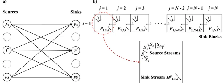
jump flow streams connecting all blocks with each other and direct connecting streams connecting
73
only adjacent blocks. The involvement of jump flows is a novelty of this work that avoids the
74
utilization of unnecessary intermediate blocks for inter-block connections. Each stream connecting
75
two adjacent blocks are placed with compressors/expanders to adjust the pressure for achieving
76
the sink requirements. Options for supplying extra hot/cold utility are provided to each block for
77
allowing nonisothermal operation. When there is no direct connecting stream, the block boundary
78
between adjacent blocks is regarded as completely restricted boundary. These blocks are collected in a
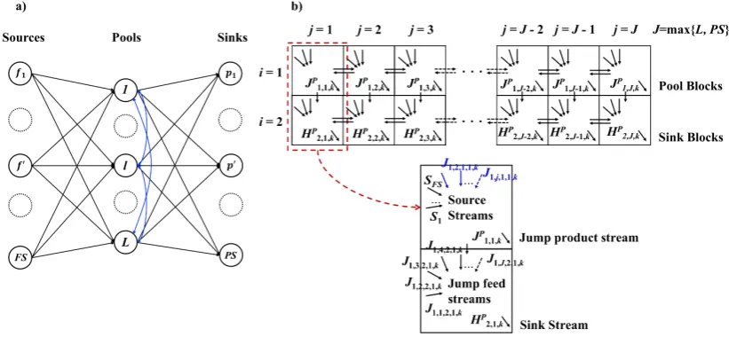
79
two-dimensional grid to form a superstructure of blocks. We formulate the fuel gas synthesis problem
80
as a mixed-integer nonlinear optimization (MINLP) problem. The model constraints involve mass and
81
energy balance, flow directions, work calculation and logic constraints. The nonlinear terms of the
82
proposed model arise from splitting, energy balances and work-related calculations.
83
The remaining of the article is structured as follows. First, we elaborate the representation of
84
fuel gas network using block-based approach. Next, we present the MINLP formulation for fuel gas
85
network synthesis problem. Finally, we demonstrate the applicability of our approach with one case
86
study from LNG plant.
87
2. Block-based Representation of Fuel Gas Network
88
In this section, we describe how the classic fuel gas network superstructure such as the one
89
proposed by Hasan et al. [5] can be represented using block-based approach [1,30] as a generic tool for
90
designing fuel gas utilization system. First, we illustrate the classical FGN superstructure and analyze
91
the operation involved in synthesizing a FGN. Next, we construct a block superstructure that also can
92
include the same features. We provide block superstructures for fuel gas network with or without
93
intermediate pools which bring additional mixing operations for more economic benefits.
94
In a classical FGN superstructure (Hasan et.al [5]), shown in Figure1, there areFSnumber of fuel
95
gas sources andPSnumber of fuel gas sinks. The source stream f has the temperature asTf and the 96
pressure asPf. The sink streampis obtained with temperature range asTpmin,Tpmax
and pressure
97
range as
Pmin p ,Ppmax
. Each streamFf,pconnecting a source f and a sinkppasses through two utility 98
exchangers (heater and/or cooler) and one mover (compressor or expander). The sources completely
99
or partially come from different fuel gas sources and are mixed at different fuel gas sinks with different
100
temperature, pressure and quality requirements. The operations in a FGN problem typically include
101
mixing, cooling, heating, pressurizing and depressurizing.
102
Most FGN synthesis problems involve multiple sources and multiple sinks. In addition, there are
103
similar equipment assignment that are assigned between sources and sinks. This allows us to develop
104
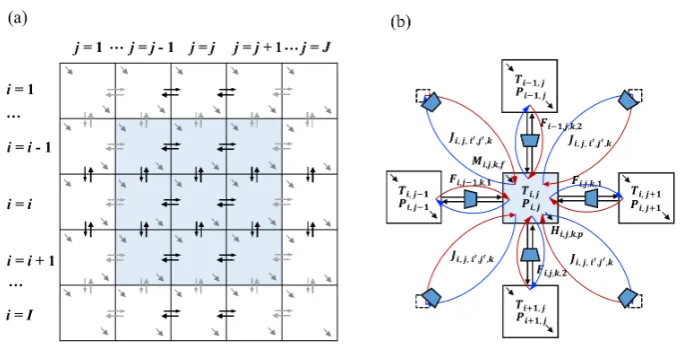
a general block representation for FGN synthesis as shown in Figure2. It involvesInumber of rows
105
andJnumber of columns, where each row or column is a collection of blocks. LetBi,jrepresent the 106
block at rowiand columnj. Each block allows multiple feed streamsMi,j,k,f to enter blockBi,j. The 107
available amount of feed f can be partially or completely fed into a blockBi,jwithz f eed f rac
i,j,f fraction 108
of available amountFff eed. Similarly, product streampcan be withdrawn from each block with the
109
Figure 2. Construction of superstructure for fuel gas synthesis problems: (a)Block superstructure illustration.(b)Block interaction through via connecting streams (blue line: jump product from the blockBi,j; red line: jump feed into the blockBi,j; blocks at diagonal positions are ignored for simplicity).
As shown in Figure2b, the mass and energy transfer within the block superstructure is achieved
111
through the direct connecting streams between adjacent blocks and jump connecting streams among
112
all blocks. Direct connecting streams are achieved via inter-block flowFi,j,k,d, which is the flowrate 113
of componentkbetween blockBi,jandBi,j+1when the flow alignmentd = 1 (the connecting flow
114
between adjacent blocks is in horizontal direction) or the flowrate of componentkbetween blockBi,j 115
andBi+1,jwhen the flow alignmentd=2 (the connecting flow between adjacent blocks is in vertical 116
direction) . These direct connecting streams can be either positive when the flow is from blockBi,jto 117
Bi,j+1ford=1 (from blockBi,j toBi+1,jford=2) or negative when the flow is from blockBi,j+1to
118
Bi,jford=1 (from blockBi+1,jtoBi,jford=2). Also, these direct connecting stream flow across the 119
block boundary between adjacent blocks. When there is no direct connecting stream (Fi,j,k,d=0), the 120
block boundary betweenBi,jandBi,j+1(d=1) or betweenBi,jandBi+1,j(d=2) is identified as completely 121
restricted boundary. The jump connecting streams are depicted byJi,j,i0,j0,k, which is the flowrate of
122
componentkfrom blockBi,jtoBi0,j0, wherei0andj0designate the row number and column number
123
of a different block. Because of this unidirectional feature, Ji,j,i0,j0,kis regarded as an jump product
124
withdrawn fromBi,j. Similarly,Ji,j,i0,j0,kis regarded as an jump feed supplied toBi0,j0.
125
With these direct and jump connecting streams, blocks with multiple inlets and multiple outlets
126
can serve as stream mixers and splitters, respectively. Source block is identified when multiple external
127
feed streams enter into a block and get mixed, while blocks with external product stream are sinks.
128
Note that splitting of source stream is not regarded as a splitting operation defined in this work because
129
it could be achieved through the splitting fractionzif eed f rac,j,f of source streamf into blockBi,jand thus 130
can be regarded as supplies of multiple source streams with the same specification.
131
The operation equipment (heaters/coolers, compressors/expanders) is embedded in the block
132
superstructure through auxiliary units. To represent the pressurizing/depressurizing operation, both
133
direct connecting streams and jump connecting streams are assigned with compressor or expander
134
(only one of them would be selected). The inlet pressure for compressors/expanders is block pressure
135
Pi,jwhen direct/jump connecting streams are outlet flow fromBi,j.Pi,jis also the outlet pressure for 136
movers when direct/jump connecting streams are inlet flow toBi,j. The inlet temperature for these 137
compressors/expanders arranged at outlet streams (Fi,j,k,dandJi,j,i0,j0,k) ofBi,jis the block temperature 138
Ti,j, which is also the common temperature of outlet streams from Bi,j. The heating and cooling 139
operations are achieved through the heat dutyQhi,jand cold dutyQci,j, which are obtained from the
140
energy balance around blockBi,j. 141
The general block superstructure for FGN synthesis problem developed in Figure2can be reduced
142
to block superstructure with smaller size if the number of intermediate pools is known beforehand. As
an illustrative example, we first consider the case without intermediate pools. Knowing certain number
144
of sources and sinks together with their specification and requirement, the classical superstructure is
145
built by connecting each source and sink and shown in Figure3a. Here all stream heaters/coolers and
146
expanders/compressors are ignored for representation simplicity. As is shown in Figure3b, we use a
147
1×Nblock superstructure to incorporate the classical superstructure. In this case, the column number
148
is directly equal to number of sinks (J = PS). Since there are no intermediate pools, row number
149
I=1. Each block serves as sink block, from which product streams are withdrawn. Meanwhile, each
150
block could also function as feed block, where multiple types of source streams are fed. Specifically,
151
taking the first sink blockB1,1as an example, there could be at mostFSnumber of source streams
152
entering this block. The activation of connectivity between sources and sinks could be reflected by
153
the feed fractionzif eed f rac,j,f of different sources f. If the feed fractionzif eed f rac,j,f of source stream at the
154
sink blockBi,j is zero, then there is no connectivity between the source f and the sink p in block 155
Bi,j; source-sink connectivity exists as long as the feed fraction of source streamz f eed f rac
i,j,f is nonzero. 156
Besides, the horizontal connecting streams between adjacent blocks in Figure3b are also allowed. This
157
additional feature physically indicates the material flowing between two fuel gas sinks.
158
Figure 3.Block representation for fuel gas network problem:(a)Classical superstructure for fuel gas network.(b)Equivalent block superstructure for fuel gas network.
As for the more general case of fuel gas network superstructure, between the sources and sinks
159
layer, there is normally another layer consisting ofLnumber of intermediate pools, as is shown in
160
Figure4. Source streams first come into the intermediate pools, where certain operations such as mixing,
161
purifying are executed according to different sink requirements. The outlet streams coming from the
162
intermediate pools are further directed to the sinks or to the other different pools (shown as the blue
163
line in Figure4a). One way to incorporate the general superstructure is to utilize a block superstructure
164
with larger size so that pools (involving mixing and splitting operations) can be included into the
165
system. With this new feature of intermediate pools, the updated block superstructure is shown in
166
Figure4b. The first row consists ofLnumber of pool blocks and the second row consists ofPSnumber
167
of sink blocks. In this case, the number of columns can be taken asJ = max{L,PS}. The existence
168
of intermediate pools make the row number asI =2, one row to accommodate pools and another
169
row for sinks. The distribution of source streams into each pool blocks is achieved through splitting
170
operation of source streams. In the first row, the jump products are withdrawn from each block as
171
outlet streams of intermediate pools. Specifically, taking the first column of block superstructure in
172
Figure4b as an example, the jump productJ1,1,P k(the summation of all the jump connecting streams to
173
other blocks from blockB1,1) is withdrawn and directed to other blocks as jump feeds. These jump
174
feeds (fromJ1,2,2,1,ktoJ1,J,2,1,k) are mixed in the second row at sink blocks and then taken as the final 175
productH2,1,p k(the overall component flowrate for all product streamp). When the number of sources,
176
sinks and pools in the system is not that large, the current commercial solver could handle the FGN
design problem without the solution challenge. However, when a large-scale problem is considered,
178
the column number of two rows in this two-dimension block superstructure may not be necessarily
179
the same since we can fix the streams in redundant blocks as zero. This fixing ensures that the number
180
of blocks in the first row is only equal to the number of pools assigned in the system and the number
181
of blocks in the second row is equal to the number of sinks.
182
Figure 4. General superstructure for fuel gas network synthesis problem with intermediate pools: (a) General superstructure for fuel gas network with intermediate pools. (b) equivalent block superstructure.
As is discussed above, the block superstructure can be converted from the classical superstructure
183
of fuel gas network. When there is no priori information provided on flow connectivity among sources,
184
pools and sinks, the block superstructure can be constructed by simply setting the row numberIand
185
column numberJ(i.e.,J=max{L,PS}), which then involves as many process alternatives as possible.
186
The benefit for block representation method is on its generic feature that each block follows the same
187
pattern with multiple inlet streams and outlet streams.
188
To this end, we introduced the block-based representation for fuel gas network synthesis problems.
189
The illustrative example is on FGN synthesis with or without intermediate pools. We now develop the
190
MINLP formulation for the FGN synthesis problem.
191
3. FGN Synthesis Problem Statement
192
This section gives the formal problem description for FGN synthesis problem using block
193
superstructure. The sets given for this problem are the setK = {k|k = 1, ...,|K|} of components,
194
the set FS = {f|f = 1, ...,|FS|} of fuel gas sources with component specification ykf eed,f , a set
195
PS = {p|p = 1, ...,|PS|} of fuel gas sinks with the material demand range as
DLp, DUp
, energy
196
demand range as
DeLp,DeUp
, purity range as
ymink,p,prod,ymaxk,p ,prod
for specieskas well as other quality
197
specifications
qsmin,p,prod,qsmax,p ,prodfor qualitys. The objective is to synthesize a fuel gas network that 198
systemically utilizes the arrangement of fuel gas resources and minimizes the total annual cost. The
199
setD= {d|d= 1, 2}designates the flow alignment. The flow alignmentd =1 when the stream is
200
flowing in the horizontal direction, i.e., from blockBi,jtoBi,j+1;d=2 when the stream is flowing in
201
the vertical direction, i..e., form blockBi,jtoBi+1,j. The temperature range and flowrate range for all 202
connecting flows including direct connecting flow and jump connecting flow is set as
Tmin,Tmax
and
203
FL,FU
respectively.
We consider the assumption for this work as constant properties (heat capacity, lower heating
205
value, etc.), continuous steady-state operation, ideal gas condition, adiabatic expansion/compression,
206
and ideal mixing. With this, we now provide the description of a MINLP model for fuel gas network
207
synthesis based on block superstructure.
208
4. MINLP Model Formulation for Block-based Fuel Gas Network Synthesis
209
The main constraints for the MINLP model involve block material balance, flow directions, block
210
energy balance, work calculation and task assignment/logic constraints. The objective of the FGN
211
synthesis is to minimize the total annual cost.
212
4.1. Block Material Balance 213
The general material balance for each blockBi,j considers the material flows of componentk 214
including horizontal inlet flowFi,j−1,k,1, the horizontal outlet flowFi,j,k,1, vertical inlet flowFi−1,j,k,2,
215
vertical outlet flowFi,j,k,2, external feed streamM
f
i,j,k, external product streamH p
i,j,k, jump feed flow 216
Jif,j,k, and jump product flowJip,j,k. Specifically, the material balance relation is presented as follows.
217
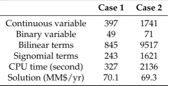
Fi,j−1,k,1−Fi,j,k,1+Fi−1,j,k,2−Fi,j,k,2+M
f i,j,k−H
p i,j,k+J
f i,j,k−J
p
i,j,k=0, i∈ I,j∈ J,k∈K (1)
The last four terms in the above relation are obtained though the following constraints.
218
Mif,j,k =
∑
f∈FSMi,j,k,f i∈ I,j∈ J,k∈K (2)
Hip,j,k=
∑
p∈PSHi,j,k,p i∈I,j∈ J,k∈K (3)
Jif,j,k=
∑
(i0,j0)∈LN
Ji0,j0,i,j,k i∈ I,j∈ J,k∈K (4)
Jip,j,k=
∑
(i0,j0)∈LN
Ji,j,i0,j0,k i∈ I,j∈ J,k∈K (5)
All variables includingMif,j,k,Hip,j,k,Jif,j,kandJip,j,kare obtained by summing multiple feeds or multiple
219
products within single blockBi,j. The positive continuous variableMi,j,k,f indicates the amount of 220
component flowratekinto blockBi,jcarried by feed stream f. The amount of componentktaken from 221
blockBi,jthrough product streampis designated by positive continuous variableHi,j,k,p. The material 222
flowrate for componentkfrom blockBi,jtoBi0,j0isJi,j,i0,j0,k. The indexi0andj0indicate row position
223
and column position of a blockBi0,j0that is different fromBi,j. The subsetLN(i,j,i0,j0)designates the
224
connection between blockBi,jand blockBi0,j0. It should be noted that for jump connecting flowJi,j,i0,j0,k,
225
i6=i0andj6=j0so as to avoid remixing in blockBi,j. The stream connectivities at the outer boundary 226
of block superstructure are neglected by settingFi=I,j,k,1=Fi,j=J,k,2=0 to ensure that the interaction
227
between the superstructure and the environment is only achieved through external feeds and products.
228
The flowrateMi,j,k,f for each feed f into block Bi,j is completely or partially from the overall 229
available amountFff eed. The distribution of feed stream f is achieved by the feed fractionzif eed f rac,j,f ≥0
230
in blockBi,j. HenceMi,j,k,f can be determined as follows: 231
Mi,j,k,f =F f eed f y
f eed k,f z
f eed f rac
i,j,f , i∈I,j∈ J,k∈K,f ∈ FS (6)
0≤
∑
i∈I
∑
j∈JTypically, headers receiving fuel gas have purity requirement for inlet streams to ensure correct
232
operating conditions of corresponding equipment. This is achieved through the following inequality
233
constraints:
234
ymink,p,prod
∑
k0∈KHi,j,k0,p≤ Hi,j,k,p≤ymaxk,p ,prod
∑
k0∈K
Hi,j,k0,p, i∈ I,j∈ J,(k,p)∈kp (8)
Here, the purity range for componentkin product streampis given by
ymink,p,prod,ymaxk,p ,prod
. The setkp 235
relates the key componentkwith product streampwith purity specifications. The product streamp 236
have no purity restrictions when it does not appear in setkp.
237
On top of purity requirement of key componentkin product streamp, possible requirement on
238
ratio of different componentkin product streampis also considered.
239
Pi,j,k=k0
,p≥
∑
k00∈K
πprod
k0,k00,pPi,j,k00,p i∈ I,j∈ J,p∈Ps (9)
whereπprod
k0,k00,pis the minimum product ratio requirement between componentk
0
and componentk00 for
240
product p.
241
We also impose the demand constraint for productpsupplied to different headers:
242
DLp≤
∑
i∈I∑
j∈Jk∑
∈KHi,j,k,p≤DUp, p∈PS (10)
Here,DpLandDUp are minimum required amount and maximum allowed amount for product stream 243
prespectively. Here depending on requirements of different fuel gas sinks, there are no information
244
provided onDLp,DUp or both. In this case, we setDpL=0 andDUp =max f∈FSF
f eed f . 245
Besides, energy demandsDepfor each product streampshould be satisfied based on the following 246
constraint:
247
∑
i∈I
∑
j∈Jk∑
∈KHi,j,k,pLHVk≥Dep, p∈PS (11)
whereLHVkrefers to lower heating value for each component k, which measures energy content per 248
unit mass or volume of pure combustible component.
249
Furthermore, each product stream should have acceptable limits on other certain specifications
250
including lower heating value (LHV), reverse specific gravity (1/SG). Assuming that all the considered
251
specifications are linearly additive based on mixture composition or have appropriate linear indices,
252
the following constraint is supplied below for each product streamp[5].
253
qmins,p,prod
∑
i∈I∑
j∈Jk∑
∈KHi,j,k,p≤
∑
i∈I∑
j∈Jk∑
∈KHi,j,k,pqs,k≤qmaxs,p ,prod
∑
i∈I∑
j∈Jk∑
∈KHi,j,k,p, p∈PS (12)
Here the parameterqs,kdenote the value of specificationsfor componentk, and
qmins,p,prod,qmaxs,p ,prod
is
254
the acceptable range of specificationsfor product streamp. Note that the quality specificationqs,kis 255
component flowrate-based instead of total flowrate-based, which is considered in the work of Hasan
256
et.al. [5].
257
To obtain the total flowrate for all streams associated with the blockBi,j, we sum all components 258
in each stream. Specifically, we obtain the toal flowrateFPiT,j,d,FNiT,j,d,JiT,j,i0,j0,MiT,j,f, andHiT,j,sfrom the
259
component flowrate forFPi,j,k,d,FNi,j,k,d,Ji,j,i0,j0,k,Mi,j,k,f, andHi,j,k,sthrough the following relations.
260
FPiT,j,d=
∑
k∈KFNiT,j,d=
∑
k∈KFNi,j,k,d, i∈I,j∈ J,d∈D (14)
JiT,j,i0,j0 =
∑
k∈K
Ji,j,i0,j0,k, (i,j,i0,j0)∈ LN(i,j,i0,j0) (15)
MTi,j,f =
∑
k∈KMi,j,k,f, i∈ I,j∈ J,f ∈FS (16)
HiT,j,p=
∑
k∈KHi,j,k,p, i∈ I,j∈ J,s∈PS (17)
With the total flowrate information, we are able to model the splitting operation for achieving identical
261
composition for all outlet streams including direction connecting streams, jump connecting streams
262
and product streams. These relations are expressed through the following constraints:
263
FPi,j,k,d=ybi,j,kFPiT,j,d i∈I,j∈J,d∈D (18) FNi,j−1,k,1=ybi,j,kFNiT,j−1,1 i∈I,j∈ J (19)
FNi−1,j,k,2=ybi,j,kFNiT−1,j,2 i∈I,j∈ J (20)
Ji,j,i0,j0,k=yib,j,kJiT,j,i0,j0 (i,j,i0,j0)∈LN(i,j,i0,j0),k∈K (21)
Hi,j,k,s=ybi,j,kHiT,j,s i∈ I,j∈ J,k∈K,s∈PS (22)
Here the positive continuous variableyb
i,j,krefers to the block composition of componentk. This block 264
composition has the physical meaning as the composition of componentkfor all outlet streams from
265
blockBi,j. 266
4.2. Flow Directions 267
The direct connectivity Fi,j,k,d among adjacent blocks is a bidirectional flow with its positive 268
componentFPi,j,k,dand negative componentFNi,j,k,d. Only one of the component is active when the 269
connecting flowFi,j,k,dis chosen to be nonzero. The selection of flow direction is a decision variable, 270
which is achieved through the following binary variable:
271
ziPlus,j,d =
(
True ifFi,j,k,dis from blockBi,jtoBi,j+1(d=1) or from blockBi,jtoBi+1,j(d=2)
False otherwise
As a result, the flow direction determination is achieved though the following constraints:
272
Fi,j,k,d=FPi,j,k,d−FNi,j,k,d i∈ I,j∈ J,k∈K,d∈D (23) FPi,j,k,d≤FUziPlus,j,d, i∈ I,j∈ J,k∈K,d∈D (24) FNi,j,k,d≤FU(1−zPlusi,j,d), i∈ I,j∈ J,k∈K,d∈D (25) 4.3. Block Energy Balance
273
The involved enthalpy terms for block energy balance includes stream enthalpy, feed enthalpy,
274
product enthalpy, external heating/cooling, work energy associated with expansion/compression.
275
Then the steady-state energy balance for blockBi,jis formulated as follows: 276
where,EFi,j,drepresents the stream enthalpy carried by the material flowFi,j,k,din flow directiond, 277
EMi,jis the overall enthalpy brought into blockBi,jalong with feed streams ,EPi,jis overall enthalpy 278
taken away by product streams,EJif,jis overall enthalpy carried into block Bi,jthrough jump feed, 279
EJip,j is overall enthalpy taken out from blockBi,j through jump product,Qi,jrepresents amount of 280
heat/cold utility consumed in blockBi,j,Wi,j indicates the amount of work energy added into or 281
withdrawn from blockBi,j. These energy flow variables are shown in Figure5. 282
Figure 5.Illustration of energy balance on blockBi,j.
The stream enthalpy is determined as follows with the information provided on flowrate,
283
component heat capacities and the block temperature. Depending on the flow direction, in flow
284
alignmentd=1, the inlet temperature for blockBi,jis eitherTi,jfrom blockBi,jtoBi,j+1orTi,j+1from
285
blockBi,j+1toBi,j; in flow alignmentd=2, the inlet temperature for blockBi,jis eitherTi,jfrom block 286
Bi,jtoBi+1,jorTi+1,jfrom blockBi+1,jtoBi,j. 287
EFi,j,1=
∑
k∈K
FPi,j,k,1CpkTi,j−
∑
k∈KFNi,j,k,1CpkTi,j+1 (27)
EFi,j,2=
∑
k∈K
FPi,j,k,2CpkTi,j−
∑
k∈KFNi,j,k,2CpkTi+1,j (28)
whereCpkis the heat capacity of componentk. 288
The enthalpy amount brought into or withdrawn from block Bi,j through jump flows are 289
determined as follows:
290
EJif,j =
∑
k∈K(i0,j
∑
0)∈LNCpkTi0,j0Ji0,j0,i,j,k i∈I,j∈J (29)
EJip,j=
∑
k∈K(i0,j
∑
0)∈LNCpkTi,jJi,j,i0,j0,k i∈ I,j∈ J (30)
It should be noted that the inlet temperature of jump flow is always the temperature of source block
291
Ti,j. Likewise, the feed enthalpy and product enthalpy are determined with the following constraints: 292
EMi,j =
∑
k∈Kf∑
∈FMi,j,k,fCpkTf i∈ I,j∈ J (31)
EPi,j=
∑
k∈Kp∑
∈PPi,j,k,pCpkTi,j i∈ I,j∈ J (32)
The amount of heat/cold utility consumed in blockBi,jcan be evaluated through the amount of heat 293
Qi,j =Qih,j−Qci,j (33)
The work energy can be also determined by the amount of work added into or taken out of blockBi,j, 295
which are denoted asWicom,j for compression andWiexp,j for expansion respectively. The calculation of
296
Wicom,j andWiexp,j is explained later in this Section4.6.
297
Wi,j=Wicom,j −W exp
i,j (34)
Finally, to prevent condensation in the process integration network and ensure sufficient superheating,
298
the following constraints are supplied for product streampin blockBi,j[5]. 299
∑
k∈K
Hi,j,k,pCpkTi,j≥(MDPp+5
9(5.15
Pi,j
100−312)k
∑
∈KHi,j,k,pCpk i∈ I,j∈ J,p∈PS (35)∑
k∈K
Hi,j,k,pCpkTi,j≤(HDPp+5
9(2.33(
Pi,j
100)
2−2.8Pi,j
100−305)k
∑
∈KHi,j,k,pCpk i∈ I,j∈ J,p∈PS (36) where parameterMDPpis moisture dew-point temperature and parameterHDPpis the hydrocarbon 300dew-point temperature for the productp.
301
4.4. Product Stream Assignments and Logical Constraints 302
We define binary variables for each product streampat blockBi,jto determine whether they are 303
active inBi,jor not: 304
ziproduct,j,p =
(
1 if product streampis withdrawn from blockBi,j
0 otherwise
The identification of block as product block is achieved through the following logical relation,
305
which involves product binary variable.
306
∑
k∈K
Pi,j,k,p≤DUpz product
i,j,p i∈ I,j∈ J,p∈PS (37)
For each block, there are at most one type of product stream present in blockBi,j. The logic proposition 307
is illustrated as follows:
308
∑
p∈PS
ziproduct,j,p ≤1 i∈ I,j∈ J (38)
Each product streampappears in the block superstructure for at least once so as to ensure the supply
309
of fuel gas header.
310
∑
i∈I
∑
j∈Jziproduct,j,p ≥1 p∈PS (39)
The temperature range for block with product streampis fromTpmintoTpmax. 311
Tpminz product
i,j,p +Tmin(1−z product
i,j,p )≤Ti,j ≤Tmaxp z product
i,j,p +Tmax(1−z product
i,j,p ) i∈ I,j∈ J,p∈PS (40)
Likewise, the pressure range for product block is
Pmin
p toPpmax
.
Ppminz product
i,j,p +Pmin(1−z product
i,j,p )≤Ti,j ≤Ppmaxz product
i,j,p +Pmax(1−z product
i,j,p ) i∈I,j∈ J,p∈ PS (41) 4.5. Boundary Assignment
313
The boundary type between adjacent blocks can be either completely restricted or not. If there
314
is no direct connecting stream between adjacent blocks, then the inter-block boundary is identified
315
as completely restricted boundary. The decision of boundary type is achieved through the following
316
binary variablezcri,j,d.
317
zcri,j,d=
1 If boundary between Bi,jand Bi,j+1for d=1 (between Bi,jand Bi+1,jfor d=2) is completetly restricted
0 Otherwise
According to the definition of completely restricted boundary, the following constraints are supplied
318
to relate flowrateFi,j,k,dwith boundary type. 319
Fi,j,k,d≤FU(1−zcri,j,d), i∈I,j∈ J,d∈D (42) 4.6. Work Calculation
320
The work termWi,j consists of compression work termWicom,j and expansion work termW exp i,j . 321
BothWicom,j andWiexp,j consist of work components for direct connecting streams (Wicomp,j,d ,FPfor positive
322
component,Wicomp,j,d ,FNfor negative component), feed streams(Wicomp,j,f ,FS), and jump connecting streams
323
(Wicomp0,j0,i,,jJ f). Accordingly,
324
Wicom,j =
∑
d∈D(Wicomp,j,d ,FP+Wicomp,j,d ,FN) +
∑
f∈FSWicomp,j,f ,FS+
∑
(i0,j0)∈LN(i,j,i0,j0)
Wicomp0,j0,i,j,J f, i∈ I,j∈ J (43)
Wiexp,j =
∑
d∈D(Wiexp,j,d,FP+Wiexp,j,d,FN) +
∑
f∈FSWiexp,j,f,FS+
∑
(i0,j0)∈LN(i,j,i0,j0)
Wicomp,j,i0,j0,J p, i∈I,j∈ J (44)
We define the positive variablePRiF,j,dto designate the pressure ratio between the blockBi,j+1andBi,j 325
for flow alignmentd=1 or between the blockBi+1,jandBi,jfor flow alignmentd=2. The calculation 326
ofPRFi,j,dis activated when the boundary of blockBi,jis not completely restricted at the corresponding 327
flow alignmentd(zcri,j,d=0). Otherwise, the pressure ratio is taken as 1 to avoid the calculation of the
328
pressure ratio. In horizontal direction, the pressure ratio is determined as follows:
329
Pi,j+1
Pi,j
−PRupzcri,j,1≤PRFi,j,1≤ Pi,j+1 Pi,j
+PRupzicr,j,1 i∈ I,j∈ J (45)
1−PRup(1−zcri,j,1)≤PRFi,j,1≤1+PRup(1−zcri,j,1) i∈ I,j∈ J (46) Here,PRupis taken as the maximum pressure ratio, which is determined asPmax/Pmin. Similarly, in
330
vertical direction, the pressure ratio is determined as follows:
331
Pi+1,j Pi,j
−PRupzcri,j,2≤PRFi,j,2≤ Pi+1,j Pi,j
+PRupzicr,j,2 i∈ I,j∈ J (47)
For feed stream f, the pressure ratio is taken as the ratio between block pressurePi,jand parameter 332
Pff eedfor feed pressure .
333
PRif eed,j,f = Pi,j Pff eed i
∈ I,j∈ J,f ∈FS (49)
From these pressure ratio definitions, we calculate the isentropic work on direct connecting streams,
334
feed streams and jump connecting streams. In the horizontal direction, the inlet isentropic work is
335
determined as follows:
336
ηWicomp,j,1 ,FP−Wiexp,j,1,FP/η=
∑
k∈K
FPi,j−1,k,1Tis,j−1,1Rgas γ
γ−1{(PR
F i,j−1,1)
γ−1
γ −1} i∈ I,j∈ J (50)
ηWicomp,j,1 ,FN−Wiexp,j,1,FN/η=
∑
k∈K
FNi,j,k,1Tis,j,1Rgas γ
γ−1{(
1
PRiF,j,1)
γ−1
γ −1} i∈ I,j∈ J (51)
Here Rgas is the gas constant and γ is the adiabatic compression coefficient. η is the adiabatic
337
compression efficiency. Similarly, the isentropic work for a vertical entering stream is calculated
338
as follows:
339
ηWicomp,j,2 ,FP−Wiexp,j,2,FP/η=
∑
k∈K
FPi−1,j,k,2Tis−1,j,2Rgas γ
γ−1{(PR
F i−1,j,2)
γ−1
γ −1} i∈ I,j∈ J (52)
ηWicomp,j,2 ,FN−Wiexp,j,2,FN/η=
∑
k∈K
FNi,j,k,2Tis,j,2Rgas
γ
γ−1{(
1
PRF i,j,2
)γ−γ1 −1} i∈ I,j∈ J (53)
The work terms related to feed streams and jump connecting streams are calculated in a similar way:
340
ηWicomp,j,f ,FS−Wiexp,j,f,FS/η=
∑
k∈K
Mi,j,k,fTff eedRgas 1 nf s
{(PRif eed,j,f)nf s−1} i∈ I,j∈ J,f ∈FS (54)
ηWicomp,j,i0,j0,JF−W
exp,JF
i,j,i0,j0 /η=JiT,j,i0,j0Ti,jRgas
γ
γ−1{(
Pi0,j0 Pi,j
)γ−γ1 −1} (i,j,i0,j)∈ LN(i,j,i0,j0) (55)
Herenf sis the adiabatic compression coefficient. 341
4.7. Objective Function 342
We consider the components of economic objective in the work of Hasan et al. [5] and derive the objective function for the FGN synthesis as follows.
min TAC=
∑
f∈FS (
∑
i∈I
∑
j∈J UFCfFf eed f z
f eed f rac
i,j,f +Dif(F f eed
f −
∑
i∈I
∑
j∈JFff eedzif eed f rac,j,f ))
−
∑
p∈PS
Revp(
∑
k∈KLHVk
∑
i∈I∑
j∈JHi,j,k,ps−Dep) +
∑
i∈I
∑
j∈Jf∑
∈FSπfFff eedzif eed f rac,j,f +CCHU
∑
i∈I
∑
j∈JQhi,j+CCCU
∑
i∈I∑
j∈JQci,j+CCexp
∑
i∈I∑
j∈JWiexp,j +CCcom
∑
i∈I∑
j∈JWicom,j
(56)
This objective function aims at minimizing total annual cost (TAC). Here parameterUFCf is the unit 343
cost of different source streams,Dif is the unit cost of treatment cost for the remaining source stream, 344
Revpis the unit profit from excess energy in product streamp. Besides, the parameterπf denotes the 345
unit transportation cost for source streamf. ParametersCCHU,CCCU,CCexpandCCcomdenote the
unit cost of heaters, coolers, expansion operations and compression operations, respectively. The first
347
term in the objective function consists of source stream purchase cost and disposal cost. The second
348
term corresponds to the profit gained from the released excess amount of energy in product streamp.
349
The third term indicates the transporting cost of source streams. The last four terms refer to overall
350
cost (both capital cost and operating cost) for heaters, coolers, expansion operations and compression
351
operations.
352
5. Case Study
353
In this section, the fuel gas network synthesis problem with two scenarios are presented to
354
demonstrate the application of block superstructure in synthesis of FGN. We consider two cases: case
355
1 for representation without intermediate pools; case 2 for representation with intermediate pools. The
356
case study is from the work of Hasan et al. [5] and all problem instances are solved using ANTIGONE
357
1.1. [31] in GAMS 24.4 on a Dell Optiplex 9020 computer (Intel 8 Core i7-4770 CPU 3.4 GHz, 15.5 GB
358
memory) running Springdale Linux.
359
5.1. Case Study Description 360
Although the definition of fuel gas network is taken from the literature (Hasan et al. [5]), the
361
model we utilized in this work is not based on the total flowrate but the component flowrate. Because
362
of the model discrepancy, we keep part of the source data from the literature in Table1and update
363
required component parameters in Table2. The sink data is directly taken from the literature without
364
any changes and listed in Table3. It should be noted that all the data have been converted to standard
365
units.
366
Table 1.Sources streams specifications.
Specification/parameter EFG HPFG TBOG FFF
Adiabatic compression coefficient,nf s 0.254 0.2 0.18 0.2 Availability,Fff eed(kmol/s) 0.92938 0.05310 0.18255 <7.30229
Temperature,Tff eed(K) 240 325 113 298
Pressure,Pff eed(bar) 1.72369 7.58423 1.72369 26.20007
Methane, CH4(%) 60.0 81.0 92.0 85.0
Ethane, C2H6(%) 0.0 6.0 0.0 5.0
Propane, C3H8(%) 0.0 5.0 0.0 4.0
C3+(%) 0.0 2.5 0.0 2.0
CO (%) 0.0 0.0 0.0 0.05
N2 (%) 40.0 5.5 8.0 3.95
Source unit cost,UFCf ($/kmol) 0.0 0.0 0.0 4.184 Source disposal cost,Dif ($/kmol) 0.209 0.292 0.209 0 Feed transporting cost,πf ($/kmol) 0.0008 0.0008 0.0008 0.0008
Table 2.Component quality parameters.
Parameter Methane Ethane Propane C3+ CO N2
LHV(MJ/kmol) 800.234 1425.580 2041.113 2654.134 282.637 0 1/SG (28.96/mol wt) 1.8060 0.9636 0.6571 0.4985 1.0344 1.0342
Table 3.Specification for product streams (sinks).
Specification/parameter C1 C2 C3 C4 C5
Energy demand,Dep(MJ/s) 152.309 149.378 120.305 149.378 87.921
Material demand,
DLp,DUp
(kmol/s) 0.159 - 0.172 0.156 - 0.169 0.159 - 0.172 0.149 - 0.169 0.132 - 0.199 Temperature range,
Tpmin,Tpmax
(K) 113-1000 113-1000 113-1000 113-1000 113-1000
Pressure range,
Pmin p ,Pmaxp
(bar) 1.72-24.82 1.72-24.82 1.72-24.82 1.72-24.82 1.72-24.82
MDPp(K) 277 277 277 277 277
HDPp(K) 277 277 277 277 277
LHV(MJ/kmol) 264.885- 264.885- 264.885- 264.885-
264.885-8829.500 8829.500 8829.500 8829.500 8829.500
1/SG(28.96/mol wt) 1.0-2.4 1.0-2.4 1.0-2.4 1.0-2.4 1.0-2.4
Methane, CH4(%) >85.0 >85.0 >85.0 >85.0 >65.0
Ethane, C2H6(%) <15.0 <15.0 <15.0 <15.0 <15.0 Propane, C3H8(%) <15.0 <15.0 <15.0 <15.0 <15.0
C3+(%) <5.0 <5.0 <5.0 <5.0 <5.0
CO (%) <10.0 <10.0 <10.0 <10.0 <10.0
N2 (%) <15.0 <15.0 <15.0 <15.0 <15.0
Treatment factor,ψsp 1.0 1.0 1.0 1.0 1.0
Unit profit,Revp($/KJ) 0 0 0 0 6.6347×10⁻⁶
There are totally four source streams (S1, S2, S3, and S4) and five sink streams (C1, C2, C3, C4,
367
and C5). S1, S2 and S3are gas streams from end flash gas (EFG), high-pressure fuel gas (HPFG),
368
and tankage boil-off gas (TBOG) respectively. S4is supplied as the fuel from feed (FFF) because S1,
369
S2, S3would not be enough to meet the complete energy demand of LNG plant. The five sinks are
370
clarified according to similarity of specification among fourteen units [four gas turbine generators
371
(GTG) for power generation, two gas turbine drivers (GTDs) for the propane cycle, three GTDs for the
372
mixed refrigerant (MR) cycle, and five boilers] that consume fuel in the plant. Table4lists the cost
373
parameter including capital expenditure (CAPEX) and operating expenditure (OPEX) for various FGN
374
units (heaters/coolers, and compressors/expanders). Finally, we assign temperature lower bound as
375
Tmin=113 K, temperature upper bound asTmax=1000 K. The transporting cost for each source stream f 376
isπf =8.37×10⁻⁴$/kmol. The operating time per year is 365 days. 377
Table 4.CAPEX and OPEX Coefficients for Various Equipment Units.
Unit CAPEX ($/KWh) OPEX ($/KWh) Total ($/KWh)
Compressor 10 0.01 CCcom=10.01
Expander 1 0.05 CCexp=1.05
Heater 5 0.01 CCHU=5.01
Cooler 5 0.02 CCCU=5.02
5.2. Case 1: FGN Synthesis Without Pools 378
In this case, the block representation of FGN shown in Figure3is used. To avoid part of product
379
stream recycled as feed into adjacent blocks through direct connecting flow, all the horizontal and
380
vertical material flow, namelyFi,j,k,d=1andFi,j,k,d=2, are ignored for each product block. Accordingly,
381
horizontal (d=1) and vertical (d=2) energy flow,EFi,j,d, as well as their associated work terms are 382
removed from energy balance. Also jump connecting streams from product blocks are fixed to be zero
383
since they make the product blocks as intermediate pools.
384
The model for FGN without intermediate pools has 397 continuous variables, 49 binary variables,
385
845 bilinear terms, 243 signomial terms. The solution is obtained within 327 CPU seconds with optimal
386
total annual cost as 70,136,064 $/yr and optimality gap as 0.1%. The optimal solution reported in the
387
literature [5] is 79,943,071 $/yr. This 12.27 % reduction in TAC could be possibly attributed to the facts
388
that: (1) we do not consider the nonlinear quality in this work, i.e., wobbe index, which brings less
strict requirement on network design; and (2) we consider expanders (ideal gas assumption) instead of
390
valves (modeling based on real gas [5]) for expansion operation. The optimal block configuration for
391
FGN and its corresponding optimal network are shown in Figure6a and6b respectively.
392
In the block representation of the optimal result (Figure6a), the blockB1,1 takes compressed
393
streams from source EFG, HPFG, and TBOG and expanded stream from source FFF while supplying
394
sink stream to header C4. Both the blockB1,2and blockB1,3collect part of compressed streams from
395
source HBFG and TBOG and expanded stream from source FFF to generate sink stream for header
396
C1and C5respectively. In blockB1,4, partial compressed streams from source EFG and TBOG mix
397
with expanded stream from source FFF. This block yields the sink stream for header C2. The blockB1,5
398
blend streams from source EFG and TBOG to yield a product stream for header C3.
399
This obtained block representation is converted into FGN network shown in Figure6b. It utilizes
400
both HPFG and TBOG fully. Among all sink streams, only C4uses all source streams EFG, HPFG,
401
TBOG, FFF while C1, C5only use HPFG, TBPG, and FFF as source streams. SinkC2blends streams
402
from EFG, HPFG, and TBOG. Sink C3takes source streams from EFG, and TBOG. It should be noted
403
that both C2and C3accept part of EFG. The whole FGN network only could utilize 2.716% of EFG and
404
the rest of it goes to flare. The reason is that EFG contains low methane (60%) and high inert content
405
(40%). To utilize EFG as much as possible, it should be mixed with other source streams; however, such
406
mixing could bring unacceptable large flows to sinks so EFG is only partially utilized in the system.
407
Considering the price for FFF, none of sinks are taking it alone and sink C3 does not use FFF at all.
408
The optimal header pressures are 24.82, 24.82, 1.72, 24.82, and 1.78 bar for header C1-C5. The flow
409
rate of sink stream at headers at C1-C5are 0.172, 0.169, 0.172, 0.169, 0.199 kmol/s respectively. The
410
optimal header temperatures are reported as 297.21, 296.21, 130.11, 296.04, 280.18 K for header C1-C5
411
respectively. HPFG needs expanders before mixing with TBOG (1.72 bar) and FFF (1.72 bar) in C5
412
because of its high pressure (7.58 bar). Similarly, all the FFF (26.20 bar) needs compressors so as to
413
mix with other flows in C1, C2, C4and C5. However, EFG and TBOG do not need any compressors or
414
expanders before entering C3, which are at 1.72 bar.
415
5.3. Case 2: FGN Synthesis With Pools 416
To investigate the influence of existence of pools on improving the economic performance of
417
FGN, we use the representation shown in Figure4. The material balance involving jump connecting
418
streams is utilized to build connection between pool blocks and product blocks. For the jump product
419
Jip,j,kwithdrawn from the pool block, it is distributed back into other pool blocks or product block. To
420
avoid self-recycle of the jump product, the jump feed coming from the same block is fixed to be zero,
421
Ji,j,i0,j0,k=0, wherei=i0andj=j0. External feed streams are only allowed to enter into the first row
422
with pool blocks while external product streams are only withdrawn from the second row with sink
423
blocks.
424
We solve the model for FGN with intermediate pools using ANTIGONE as the MINLP solver. The
425
model contains 1741 continuous variables, 71 binary variables, 9517 bilinear terms and 1621 signomial
426
terms. The comparison of model statistics for these two cases are summarized in Table5. The solution
427
is obtained within 2136 CPU seconds with optimal total annual cost as 69,281,438 $/yr and optimality
428
gap as 0.1%. The involvement of intermediate pools results in a reduction of total annual profit by
429
1.22%, compared to the one reported as 70,136,064 $/yr for the fuel gas network without intermediate
430
pools. Figure7shows the optimal fuel gas network configuration.
431
Table 5.Summary of model statistics for case 1 and case 2.
Case 1 Case 2
Continuous variable 397 1741
Binary variable 49 71
Bilinear terms 845 9517 Signomial terms 243 1621 CPU time (second) 327 2136 Solution (MM$/yr) 70.1 69.3
The obtained block representation for the FGN is given in Figure 7a. Feed stream EFG is
432
distributed into block B1,3 and B1,4. Part of feed stream HPFG is expanded and then enters into
433
blockB1,4while extra amount distributes into blockB1,2. In addition, feed stream TBOG is partially
434
supplied to blockB1,3and blockB1,5. Some other amount of TBOG is compressed and then enter block
435
B1,1. The feed stream FFF only enters the blockB1,1after expanding operation. The blocksB1,jin the 436
first row (column numberjranges from 1 to 5) collect the mixed stream and yield the jump product
437
which are supplied as jump feed in the second row. Hence, these blocks are identified as intermediate
438
pools, i.e., P1, P2, P3, P4, and P5. At the second row of the block representation, the jump product from
439
blockB1,1and blockB2,4mix at blockB2,1, which supplies product stream to sink C1and generates
440
jump product entering blockB2,5. The blockB2,2blends the jump product from blockB1,3andB1,5to
441
obtain sink stream C3. The jump product from blockB1,3compress firstly. This compressed stream
442
splits into two parts: one part mixes with jump product from blockB1,1at blockB2,3, where the sink
443
stream C4is generated; another part mixes with jump product from blockB1,1at blockB3,4, where the
444
sink stream C2is obtained. Besides, a jump product flow is withdrawn from blockB2,4and fed into
445
blockB2,1. The jump product flows from blockB2,1,B1,2are compressed and mixed with other jump
446
product flows from blockB1,4andB1,5to supply the sink stream C5.
The corresponding network structure is shown in Figure7b. The optimal network consumes both
448
HPFG and TBOG fully. Since all the blocks in the first row embed the inlet flow for mixing, five pools
449
can be identified. Pool P1accepts source stream from TBOG and FFF, which only supply feed to P1.
450
P2takes part of stream from source HPFG. P3blends streams from EFG and TBOG. Part of external
451
stream from EFG and HPFG enter pool P4while P5only takes stream from source TBOG. The outlet
452
flow from pool P1is distributed into sink C1, C2and C4. The outlet flows from pool P2and P4are
453
directly transported to sink C5. Sink C2, C3and C4accept inlet flow withdrawn from pool P3. Part of
454
the outlet flow from pool P5is recycled back to pool P4and another is transported into sink C3. Part of
455
product streams from C2and C1are recycled back to C1and C5. The utilization of EFG in the whole
456
FGN network is only 4.51% and the rest of it goes to flare.
457
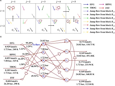
Figure 7.Block representation and process flowsheet for the optimal solution of FGN with intermediate pools: (a) Block representation for the optimal solution of FGN. (b) process flowsheet for the optimal solution of FGN.
The header pressures are 24.82, 24.82, 1.72, 24.82, and 1.72 bar for C1-C5respectively. Expanders
458
are arranged on inlet stream to P4from HPFG and inlet stream to P1from FFF. TBOG needs compressor
459
before mixing with FFF in P1because of its low pressure (7.58 bar). Compressors are placed on the
460
outlet streams of P3to sink C2and C4respectively. Expanders are arranged on the connecting stream
461
from P2to sink C5as well as the stream from sink C1to sink C5so as to meet the pressure requirement.
462
The temperature for sink stream C1-C5are 118.73, 451.46, 233.94, 168.81 and 113.04 K. In addition,
463
headers C1-C5 collect the flow rate of sink streams as 0.172, 0.169, 0.172, 0.169 and 0.199 kmol/s
464
respectively.
465
To summarize for the case study section, the block-based representation method can effectively
466
handle the fuel gas synthesis problem and the involvement of intermediate pools helps to improve the
467
management of FGN network, which decreases the total annual cost.
6. Conclusions
469
We present an abstract superstructure representation for FGN synthesis, which is based on a
470
block-based arrangement of source and sink. Each block allows multiple external fuel gas source
471
streams and single fuel gas sink streams. The direct connecting streams between adjacent blocks and
472
jump connecting streams among all blocks enable many alternative ways of flowing the mass and
473
energy from sources to sinks. The blocks with multiple inlet streams serve as mixers and the blocks
474
with multiple outlet streams are splitters. These blocks form a superstructure when arranged in a
475
two-dimensional grid. The row number is determined by the number of intermediate pool layers
476
and the number of sink layers. The column number is determined by the number of intermediate
477
pools and the number of sinks. With the representation method, a MINLP model for fuel gas synthesis
478
problem was proposed with constraints on material balance, energy balance, flow directions, and work
479
calculation. A case study from LNG plant was presented for two instances: one without intermediate
480
pools and another with intermediate pools. It was shown that the fuel gas network with pools
481
could significantly reduce the total annual cost by 1.22%, compared to the fuel gas network without
482
intermediate pools. These case study revealed that the block-based representation method would
483
enable the synthesis of fuel gas network and helps to find novel network design. Note that the
484
block-based representation method is initially proposed for systematic process intensification, and then
485
applied to process synthesis. The application of block-based approach for FGN integration suggests a
486
general framework towards process intensification, integration and synthesis.
487
Acknowledgments: The authors gratefully acknowledge financial support from the U.S. National Science 488
Foundation (NSF CBET-1606027). 489
Author Contributions:J.L., S.E.D and M.M.F.H. conceived the model and prepared the manuscript. 490
Conflicts of Interest:The authors declare no conflict of interest. 491
References
492
1. Demirel, S.E.; Li, J.; Hasan, M.M.F. Systematic process intensification using building blocks. Computers &
493
Chemical Engineering2017,105, 2–38. 494
2. Tahouni, N.; Gholami, M.; Panjeshahi, M.H. Integration of flare gas with fuel gas network in refineries. 495
Energy2016,111, 82–91. 496
3. Zhang, J.; Zhu, X.; Towler, G. A simultaneous optimization strategy for overall integration in refinery 497
planning.Industrial & Engineering Chemistry Research2001,40, 2640–2653. 498
4. Pellegrino, J.; Brueske, S.; Carole, T.; Andres, H. Energy and Environmental Profile of the US Petroleum 499
Refining Industry. Technical report, EERE Publication and Product Library, 2007. 500
5. Hasan, M.M.F.; Karimi, I.A.; Avison, C.M. Preliminary synthesis of fuel gas networks to conserve energy 501
and preserve the environment.Industrial & Engineering Chemistry Research2011,50, 7414–7427. 502
6. U.S. Department of Energy (DOE): Refinery Capacity 2017; Number Energy Information Administration, 2017. 503
7. De Carli, A.; Falzini, S.; Liberatore, R.; Tomei, D. Intelligent management and control of fuel gas network. 504
IECON 02. IEEE, 2002, Vol. 4, pp. 2921–2926. 505
8. Zhou, L.; Liao, Z.; Wang, J.; Jiang, B.; Yang, Y.; Du, W. Energy configuration and operation optimization of 506
refinery fuel gas networks.Applied Energy2015,139, 365–375. 507
9. Zhang, J.; Rong, G. An MILP model for multi-period optimization of fuel gas system scheduling in refinery 508
and its marginal value analysis. Chemical Engineering Research and Design2008,86, 141–151. 509
10. Zhang, J.; Rong, G.; Hou, W.; Huang, C. Simulation based approach for optimal scheduling of fuel gas 510
system in refinery.Chemical Engineering Research and Design2010,88, 87–99. 511
11. White, D.C.; others. Advanced automation technology reduces refinery energy costs. Oil & Gas Journal
512
2005,103, 45–53. 513
12. Ismail, O.S.; Umukoro, G.E. Global impact of gas flaring. Energy and Power Engineering2012,4, 290. 514
13. Fawole, O.G.; Cai, X.M.; MacKenzie, A. Gas flaring and resultant air pollution: A review focusing on black 515
14. Quan, C.; Gao, N.; Wu, C. Utilization of NiO/porous ceramic monolithic catalyst for upgrading biomass 517
fuel gas.Journal of the Energy Institute2017. 518
15. Mokheimer, E.M.; Dabwan, Y.N.; Habib, M.A. Optimal integration of solar energy with fossil fuel gas 519
turbine cogeneration plants using three different CSP technologies in Saudi Arabia.Applied Energy2017, 520
185, 1268–1280. 521
16. Friedler, F. Process integration, modelling and optimisation for energy saving and pollution reduction. 522
Applied Thermal Engineering2010,30, 2270–2280. 523
17. El-Halwagi, M.M. Pollution prevention through process integration. Clean Products and Processes1998, 524
1, 5–19. 525
18. Jagannath, A.; Hasan, M.M.F.; Al-Fadhli, F.M.; Karimi, I.A.; Allen, D.T. Minimize flaring through integration 526
with fuel gas networks. Industrial & Engineering Chemistry Research2012,51, 12630–12641. 527
19. Tahouni, N.; Gholami, M.; Panjeshahi, M. Reducing energy consumption and GHG emission by integration 528
of flare gas with fuel gas network in refinery. International Journal of Chemical, Nuclear, Materials and
529
Metallurgical Eng2014,8, 900–904. 530
20. Kondili, E.; Pantelides, C.; Sargent, R. A general algorithm for short-term scheduling of batch operations—I. 531
MILP formulation.Computers & Chemical Engineering1993,17, 211–227. 532
21. Yeomans, H.; Grossmann, I.E. A systematic modeling framework of superstructure optimization in process 533
synthesis. Computers & Chemical Engineering1999,23, 709–731. 534
22. Friedler, F.; Tarjan, K.; Huang, Y.; Fan, L. Graph-theoretic approach to process synthesis: axioms and 535
theorems. Chemical Engineering Science1992,47, 1973–1988. 536
23. Friedler, F.; Tarjan, K.; Huang, Y.; Fan, L. Graph-theoretic approach to process synthesis: polynomial 537
algorithm for maximal structure generation.Computers & Chemical Engineering1993,17, 929–942. 538
24. Bagajewicz, M.J.; Manousiouthakis, V. Mass/heat-exchange network representation of distillation networks. 539
AIChE Journal1992,38, 1769–1800. 540
25. Bagajewicz, M.J.; Pham, R.; Manousiouthakis, V. On the state space approach to mass/heat exchanger 541
network design. Chemical Engineering Science1998,53, 2595–2621. 542
26. Wu, W.; Henao, C.A.; Maravelias, C.T. A superstructure representation, generation, and modeling 543
framework for chemical process synthesis. AIChE Journal2016,62, 3199–3214. 544
27. Wu, W.; Yenkie, K.; Maravelias, C.T. A superstructure-based framework for bio-separation network 545
synthesis. Computers & Chemical Engineering2017,96, 1–17. 546
28. Li, J.; Demirel, S.E.; Hasan, M.M.F. Simultaneous Process Synthesis and Process Intensification using 547
Building Blocks. Computer Aided Chemical Engineering2017,40, 1171–1176. 548
29. Demirel, S.E.; Li, J.; Hasan, M.M.F. A General Framework for Process Synthesis, Integration and 549
Intensification. Proceedings of the 13th International Symposium on Process System Engineering2018,Under
550
Review. 551
30. Li, J.; Demirel, S.E.; Hasan, M.M.F. Process Synthesis using Block Superstructure with Automated Flowsheet 552
Generation and Optimization. AIChE Journal2018,Under Review. 553
31. Misener, R.; Floudas, C.A. ANTIGONE: algorithms for continuous/integer g
![Figure 1. Superstructure for a fuel gas network proposed by Hasan et.al [5].](https://thumb-us.123doks.com/thumbv2/123dok_us/1068311.1607424/2.595.174.422.367.572/figure-superstructure-fuel-gas-network-proposed-hasan-et.webp)