693 | P a g e
CFD ANALYSIS OF CPU FOR COOLING OF
DESKTOP COMPUTERS
Mayank Srivastava
1, Pardeep Bishnoi
2, Dr.M.K.Sinha
31
Phd Scholar, Mechanical Department, Nit Jamshedpur, Jharkhand, (India)
2
Associate Professor, Mechanical Department, Nit Jamshedpur, Jharkhand, (India)
ABSTRACT
The life of the electronic components strongly depends upon the heat transfer which is generated within that
component or the cooling of that device. For this reason the need for forced air cooling is the main factor that
should be consider at the starting phase of electronic system design. The one of the critical parts of any
electronic device is heat sink, which dissipates heat from electronic device to surrounding. Thus the choice of an
optimal heat sink depends upon the number of geometric parameters like fin height, fin length, fin thickness,
number of fins, fin materials etc. With the help of commercially available computational fluid dynamics
software’s Icepak and Fluent, we can easily analyse the cooling effect of CPU.
Keywords: Cfd Analysis, Cpu, Temperature Contour, Velocity Contour, Fluent
I. INTRODUCTION
All electronic hardware depends on the stream and control of electrical current to perform a mixture of
capacities. At whatever point electrical current courses through a resistive component, heat is created. With
respect to suitable operation of the hardware, heat dispersal is a standout amongst the most discriminating angles
to be considered when planning an electronic gadget. Heat must be uprooted with a specific end goal to keep up
the nonstop operation. With different degrees of affectability, the unwavering quality and the execution of every
single electronic gadget are temperature subordinate. For the most part they bring down the temperature and the
change of temperature as for time, the better they are. Unadulterated conduction, regular convection or radiation
cool the segments to some amplify though today's electronic gadgets require all the more capable and muddled
frameworks to adapt to heat. Thusly new heat sinks with bigger broadened surfaces, exceedingly conductive
materials and more coolant stream are keys to diminish the heat.
M.Saini et al. [1] performed a parametric study and determine heat rejection limit of air-cooled plain fin heat
sinks for computer cooling. They obtained 103.4W as a limit for plane fin heat sink. In R.Arularasan et al.[2]
research work, optimal design of the heat sink have been carried out on a parallel plate heat sink taking
geometric parameters like fin height, fin thickness, base height and fin pitch with a constant length and width of
a heat sink using CFD study. They also validate their model with experimental results and both results were
compared. R.Mohan et al. [3] investigated fin materials, number of fins, their distribution and base plate
694 | P a g e
define chassis and CPU cooling requirement for a chassis which dissipates 313 W, with an 80W CPU. Thecooling for AGP & PCI cards is improved with PCI side vent and baffle. T.Tirupati et al. [5] analysed the
effectiveness of tangential convective cooling for the protection of structure from intense, localized thermal
loads. A.Bar-Cohen et al. [6] proposed a new concept for cooling the electronic component using the
copper-base heat sink. The thermal performance and temperature distribution for the heat sink were analysed and
present a procedure for optimizing the geometrical design parameter. To investigate flow and conjugate heat
transfer in the copper-based heat sink , a three dimensional model is developed. Ilker Tari et al. [7] analysed a
notebook computer management system using CFD package. The active and passive paths which are used for
heat dissipation are examined for different steady state operating condition. Ilker Tari et al. [8] investigated CPU
cooling in a complete computer chassis with three different heat sink and performances were compared. The
effect of mesh resolution, turbulence model selection, convergence criteria and discretization schemes were
investigated to find the best result at least computational cost. The heat sink temperature difference results and
specific thermal resistances were compared with the available experimental results. R.Biswas et al.[9] used
computational software Icepak to study the airflow in a compact electronic enclosure. The aim of their study
was to investigate the pressure loss due to the presence of the inlet and outlet grilles. C.W.Argento et al. [10]
studied system level electronic packaging thermal design computationally and compared the result with
experimental data. After that they worked on redesign of an inlet plenum. R.L.Linton et al. [11] compared the
result of complete CFD modelling of a heat sink with the experimental data. They present a technique for
representing the heat sink in a coarse manner for less time consuming solutions. Their coarse model agrees well
with the detailed model without losing the characteristics of the heat sink. P.Sathyamurthy et al. [12]
computationally studied planner and staggered heat sink performance with Fluent. The computational and
experimental results were quite satisfied. They found that the thermal performance of staggered fin
configuration is better than planner fin configuration. However the pressure drop requirements for the staggered
fin heat sink was greater than those for the planar case.
In this study we are analyzing the cooling effects of the CPU by modelling the geometry numerically by
commercially available computational fluid dynamics software’s Icepak and Fluent. The main aim of this paper
is to identify a cooling solution for the desktop computer which uses 80 W CPU and find the way to increase the
cooling rate. The design is based on a total power dissipation of 252 W. The modelling is carried out by solving
the governing equations for a flow within a closed domain. The turbulent flow is considered and finite volume
method is used to discretize the governing equations. Radiation heat transfer is neglected, the flow is considered
as steady state, viscous work is neglected and boussineq approximation is valid within the domain. The
temperature and velocity contour is then plot in post processing stage and is found that the maximum
temperature and velocity inside the CPU chassis falls within the fixed limit.
II. MATHEMATICAL FORMULATION
2.1 Assumptions
Radiation heat transfer is neglected,
695 | P a g e
Viscous work is neglected,
Boussineq approximation is valid within the domain.
Governing Equations Time-independent flow equations with turbulence are solved. The viscous dissipation term
is omitted. Therefore, the governing equations for the fluid flow and heat transfer are the following form of the
incompressible continuity equations, Navier – stokes equations x-y and z direction momentum, and energy
equations together with the equation of state.
Continuity equation:
.... (1)
X direction Momentum:
.... (2)
Y direction Momentum:
.... (3)
Z direction Momentum:
.... (4)
Energy equation:
= k + .... (5)
Equation of state:
.... (6)
Where,
.... (7)
III. NUMERICAL SIMULATION
3.1 CFD Calculation
In CFD calculations, there are three main steps.
Pre-Processing
Solver Execution
696 | P a g e
Pre-Processing is the step where the modelling goals are determined and computational grid is created. In thesecond step numerical models and boundary conditions are set to start up the solver. Solver runs until the
convergence is reached. When solver is terminated, the results are examined which is the post processing part.
3.2 Computational Domain
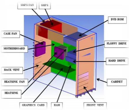
The computer chassis is the computational domain as shown in Fig. 1. It is a 3-D model of a common PC
chassis in dimensions of H x W x D = 444 x 424 x 187 mm. Since the aim of this analysis is to investigate the
temperature distribution on CPU heat sink. There are so many components attached on the computer chassis.
The complete geometry of cabinet included all components created in Ansys-Icepak software. The heat
dissipation rates, material of components are listed in Table 1. The detailed model of geometry is shown in
Fig.1. Since the aim of this analysis is to investigate the temperature and velocity distribution on CPU heat sink.
Table 1 Materials Thermal Property
Material ρ (Kg/m3) Cp (J/Kg-K) k (W/m-K)
Copper 8979 381 387.6
Aluminium 2719 871 202.4
Fr-4 1250 1300 0.35
Figure 1: Detailed Computational Domain
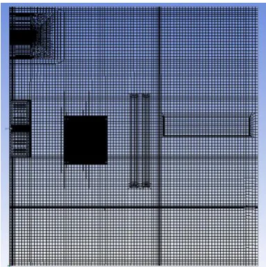
3.3 Mesh Generation
The second part of pre-processing is the mesh/grid generation as shown in Fig. 2. Mesh is the main part to get
the exact or high quality solution. In Icepak, there are three types of meshing algorithms available. These are
Hexahedral Cartesian, Hexahedral Unstructured and Tetrahedral mesh. In this analysis Hexahedral Unstructured
697 | P a g e
Figure 2: Meshing of Computational Domain
3.4 Initial Conditions
Initial velocities and temperatures are defined. Initial pressure is taken to be the ambient pressure. The
initialization of the model is important for convergence. If the initial conditions are poor, then it takes
longer to converge or it may even result in divergence.
Table 2: Meshing Detail
Mesh Type Mesh Unit Mesh parameters
Hexa-unstructured Millimetres Medium
Number of Elements 12486
Number of Nodes 18896
Fluent 6.1 uses the finite volume method. Interpolations have to be done for discretization. There are numerous
schemes, and the easiest one is the first-order upwind. The advantage of this scheme is that it converges easily.
In our model we use first order and second order schemes for pressure, momentum, temperature and RNG k-ε
turbulence model is used for turbulence kinetic energy and turbulence dissipation rate.
Table 3: Basic Parameters
Variable Solved Radiation Flow Regime Ambient Conditions
Flow (Velocity & Pressure
Off Turbulent
(RNG k-ϵ model)
Temperature 35 ◦C
Temperature Default Fluid Air
Basic Settings Advanced Settings
Iterations 1000 Discretization Scheme
Convergence Criteria Pressure Standard
Flow 0.001 Momentum First
Energy 1e-7 Temperature First
698 | P a g e
IV. RESULT AND DISCUSSION
4.1 Temperature Contour
Figure 3
:
Temperature contour of Heat sink and SMPS
Fig. 3 shows the temperature variation within the heat sink. The processor maximum temperature is at the range
of 63o C which affects significantly the functionality of the device. The fins dissipate heat quite well, which is
generated by CPU. Referring to the power supply unit, it is found that the air exits directly from the outlet fan.
The advantage of this result is that hot air from the power supply unit is not circulated in the chassis. As far as
the temperature of the chassis is concerned, it can be seen that the SMPS temperature is at very good level.
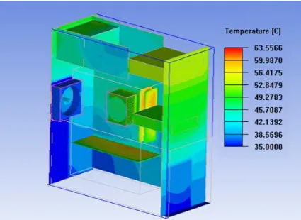
Figure 4 Temperature Contour of desktop chassis and its components
As shown in Fig. 4, Temperature of lower part of chassis is minimum because fresh air is coming in from the
lower vent .When the air absorb heat from lower components its density reduces and that hot air directly exit
699 | P a g e
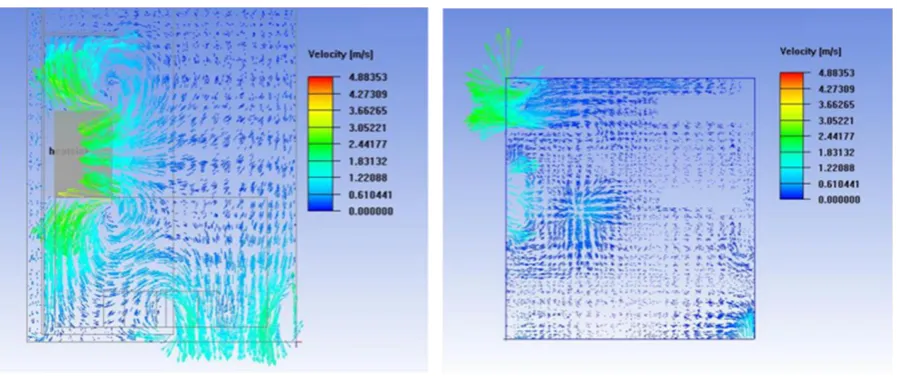
4.2 Velocity Contour
Figure 5: Velocity contour inside computational domain
As we can see in Fig. 5 air circulates around the heat sink. The heat produced by the heat source is dissipated by
the fin by conduction. When air gets contact with the fin surface, it goes up and a fresh stream of cool air
circulates near the heat sink. The space available for air circulation inside the PC chassis is limited which
decreases the heat dissipation rate therefore performance is decreased.
V. CONCLUSION
Too many fins on heat sink base is not a solution for dissipating the heat by the heat sink since they may
prevent the passage of air coming from the fan to the hottest centre parts of the heat sink. The heat transfer rate
is strongly depends upon the placement of heat sink on heat source and the fan poisoning inside the chassis. The
space inside the CPU should be sufficient to circulate the hot air which will increase the heat transfer rate. First
order discretization scheme is enough if the grid is dominated by hexahedral cells. Convergence is faster with
this scheme. RNG k-ε turbulence model is suitable for analyzing fluid flow and heat transfer in a computer
chassis.Radiation effects are ignored due to the domination of forced convection and relatively low temperature
differences inside the chassis.Convergence must be assured by checking the residuals and also the temperature
monitors. It is necessary to let the residuals to drop more than three orders of magnitude.
In this analysis we have considered a three dimensional case with a single heat sink placed on the CPU, which is
the main heat dissipation source. There exists much more scope to extend this work. For example, the analysis
can be carried out with multi heat sink, which can be mounted on some other heat source. The heat generation
rates from other components are very less as compared to the CPU but near in future as the size of chassis will
decrease & the load, working hours of electronic gadgets will increase, components dissipate more heat.
700 | P a g e
REFERENCES
[1] M.Saini and R.L,Webb, Heat rejection limits of air cooled plane fin heat sinks for computer cooling, IEEE
Transaction Component Package Technology, 26(1), 2003, 71-79.
[2] R.Arularasan and R.Velraj, CFD analysis in heat exchanger for cooling of CPU, International Journal of the
computer, the internet and management, 16(3), 2008, 1-11.
[3] R.Mohan and P.Govindarajan, Thermal analysis of CPU with variable heat sink plate thickness using CFD,
International journal of the computer, the internet and management, 18(1), 2010, 27-39.
[4] C-W. Yu and R. L. Webb, Thermal Design of a Desktop Computer System Using CFD Analysis, 17 IEEE
SEMI-THERM Symposiums.
[5] T. Tirupati and A. G. Sarwade “CFD Analysis of Convective Cooling for a Heated Skin.” Proceedings of
the 37th National & 4th International Conference on Fluid Mechanics and Fluid Power, IIT Madras,
DECEMBER-2010.
[6] A.Bar-Cohen and M.Iyengar, “ Least energy optimization of air cooled heat sinks for sustainable
development ”, IEEE Transactions on Components, Packaging, and Manufacturing Technology, Vol. 26,
no.1, pp. 16-25, March 2003.
[7] Ilker Tari and Fidan Seza Yalcin “ CFD Analysis of a Notebook Computer Thermal Management System
and a Proposed Passive Cooling Alternative.”, IEEE Transactions on Components and Packaging
Technologies Vol.33, No.2, JUNE-2010
[8] Emre Ozturk and Ilker Tari “Forced Air Cooling of CPU’s with Heat Sinks: A Numerical Study.” IEEE
Transactions on components and packaging technologies, Vol. 31, No. 3, SEPTEMBER 2008.
[9] Rebecca Biswas, Raghu B. Agarwal, Avijit Goswami, Vivek Mansingh, “Evaluation of airflow prediction
methods in compact electronic enclosures,” Fifteenth IEEE Semi-Therm Symposium, pp.
48-53,November 1999.
[10] Christopher W. Argento, Yogendra K. Joshi, Micheal D. Osterman, “Forced Convection Air-Cooling of a
commercial electronic chassis: An Experimental and Computational Case Study,” IEEE Transactions
on Components, Packaging, and Manufacturing Technology-Part A, Vol.19, No 2, pp. 248-257, 1996.
[11] Ronald L. Linton, Dereje Agonefer, “Coarse and detailed CFD modelling of a finned heat sink,” IEEE
Transactions on Components, Packaging, and Manufacturing Technology-Part A, Vol.18, pp. 517-520,
No 3, 1995.
[12] P. Sathyamurthy, P.W. Runstadler, “Numerical and Experimental Evaluation of Planar and staggered