CTO-10 & CTO-20 OZONE GENERATOR
I
I
M
M
P
P
O
O
R
R
T
T
A
A
N
N
T
T
S
S
A
A
F
F
E
E
T
T
Y
Y
I
I
N
N
S
S
T
T
R
R
U
U
C
C
T
T
I
I
O
O
N
N
S
S
When installing and using the CTO series ozone generator, basic
safety precautions should always be followed.
Be sure all the electrical power is shut OFF at the main circuit
breaker before installing the ozone laundry system.
READ AND FOLLOW ALL INSTRUCTIONS
A licensed, qualified electrician should make all permanent
electrical connections.
The electrical supply must include a suitably-rated switch or
circuit breaker to open all ungrounded supply conductors to
comply with Section 422-20 of the National Electrical Code, ANSI
/ NFPA 70-1987. The means of disconnecting the unit from the
power source must be readily accessible and located in a manner,
which will prevent incidental contact with water.
The CTO series ozone generator must be installed indoors in a
forced air ventilated room.
The CTO series ozone generator produces a high concentration
of ozone. Always make sure the electrical power is OFF when the
ozone out-put tubing is disconnected.
Never attempt any servicing while unit is wet or when power is
on.
Follow all applicable electrical codes.
CTO-10 & CTO-20 OZONE GENERATOR
TABLE OF CONTENTS
SECTION1 ... 1
GENERAL INFORMATION ... 1
1A.
D
ESCRIPTION... 1
1B.S
PECIFICATIONS... 1
1C.W
ARRANTYS
UMMARY... 1
SECTION2 ... 2
INSTALLATION ... 2
2A.L
OCATION... 2
2A-1.Location for ozone generator ... 2
2A-2. Location for oil less air pump ... 2
2B.M
OUNTING... 2
2B-1.Wall Mount for ozone generator ... 2
2B-2.Wall Mount for oil less air pump ... 2
2C.E
LECTRICAL... 3
2C-1.Main power circuit for generator ... 3
2C-2.Power circuit for air pump ... 3
2D.P
LUMBING... 3
2D-1: Plumbing for generator ... 3
2D-1A.By positive pressure diffuser: ... 3
2D-1B.By vacuum drawn injector: ... 4
2D-1C.By centrifugal air blower: ... 4
2D-2: Plumbing for air pump ... 5
SECTION 3 ... 6
OPERATION ... 6
3A.G
ENERAL... 6
3B.
N
ORMALO
PERATION... 6
3C.
S
YSTEMS
HUT-D
OWN... 6
3C-1.Ozone generator Shut-Down: ... 6
3C-2.Applied System Shut-Down: ... 6
3C-2A.For positive pressure diffuser ... 6
3C-2B.For vacuum drawn injector: ... 6
CTO-10 & CTO-20 OZONE GENERATOR
SECTION 4 ... 7
MAINTENANCE AND SERVICE ... 7
4A.S
YSTEME
LECTRO-M
ECHANICALO
VERVIEW... 7
4A-1. Indicator Lights ... 7
4A-2.Meters and gauge ... 7
4A-3. Internal Components ... 7
4B.P
REVENTATIVEM
AINTENANCES
CHEDULE... 8
4C.T
ROUBLES
HOOTING... 9
SECTION 5 ... 10
REPLACEMENT PARTS ... 10
5A.
S
TANDARD REPLACEMENT PARTS LIST: ... 10
APPENDIX: “A”
... 11
OP-1 OIL LESS AIR PUMP ASSEMBLY ... 11
APPENDIX: “B”
... 12
CD OZONE MODULE ... 12
APPENDIX: “C”
... 13
PSA OXYGEN MODULE ... 13
APPENDIX: “D”
... 13
OZONE POWER SUPPLY MODULE ... 13
APP
ENDIX: “E
-
1”
... 14
APPENDIX: “E
-
2”
... 15
SECTION1
General Information
1A. Description
BODYCARE Ozone's CTO Series ozone generators utilize corona discharge (CD) ozone generating technologies and pressure swing adsorption (PSA) oxygen concentration technologies and module design. CD Ozone generation module made from high temperature and high voltage resistance quartz glass tube , SS 316 L tube ,Knar (PVDF) end cup , Vinton "O" ring , aluminum heat sink and individual fused high frequency high voltage power supply for longer reliable use . PSA oxygen concentration module made from aluminum tube molecular sieve bed, molecular sieves select from world main manufacture, motorized distribution valve & ceramic valve seat for longer reliable use. BODYCARE Ozone's OP Series oil less air pumps utilize high grade motor, bearing, AL2O3 cylinder, Teflon diaphragm, start capacitance, cooling fun, air intake filter/muffler,
coil type after cooler and etc. for longevity and reliable running at low level noise and shock.
1B.Specifications
Generator Model: CTO-10 CTO-20 Ozone output (+10%): 10g/hr 20g/hr Flow rate (max): 5L/min 5L/min % weight O3: 2.1% 4.1 %
Power Requirements:
Domestic:
CTO-10 230VAC, 50Hz/120VAC, 60Hz both available, 1Ø, 0.6 Amps CTO-20 230VAC, 50Hz/120VAC, 60Hz both available
,
1Ø, 0.8 AmpsShipping Weight:
CTO-10: Approx. 32 kg Packages dimension (mm): 730*610*380
CTO-20: Approx. 35 kg Packages dimension (mm): 730*610*380
OP-1(Oil Less Air pump Module): Approx. 15 kg
Location Requirements:
Mounting: Wall mount in a clean, protected area. Floor mounting kit optional. Ambient Temp: 5°C - 38°C
Ventilation: Room should provide 6 air changes per hour minimum.
Protection from weather elements must be provided for outdoor installations. Operating outside of the recommended temperature ranges may result in damage not covered under
the manufacturer‟s warranty.
1C.Warranty Summary
Limited Warranty:
All CTO series ozone generator and oil less pump covered with one year warranty under normal operating conditions and procedures as described in the owner/operator manual supplied with each product.
CTO-10 & CTO-20 OZONE GENERATOR
2
SECTION2
Installation
2A.Location
2A-1.Location for ozone generator
The CTO-10 and CTO-20 are designed for wall mounting. See figure 1A. Mount generator in a clean, protected area, either indoors or outdoors. (See location requirements section 1A) Locating generator is distance from corner at least 1m. Allow sufficient access for maintenance and all tubing and electrical wires. Ozone generator should be installed no less than 1.5m above the ground.
Figure 1A
This Figure is the CTO-10&20 out side view.
2A-2. Location for oil less air pump
Mount oil less air pump left side of ozone generator. The pump should be installed no less than 1.5m above the ground.
2B.Mounting
2B-1.Wall Mount for ozone generator
Mount four m8 expansion bolts on the wall as the position as the holes of mounting legs of ozone generator in the Figure 1A.
2B-2.Wall Mount for oil less air pump
Mount two m8 expansion bolts on the wall as the position as the holes of the pump‟s
CTO-10 & CTO-20 OZONE GENERATOR
3
Figure 1B
2C.Electrical
2C-1.Main power circuit for generator
The CTO-10, CTO-20 are supplied with a standard power cord. Plug the cord into a standard 230V, three pins socket with ground pin .NOTE: To meet high grade electrical safety code, a ground-fault circuit interrupter (G.F.C.I.) need installed in inlet main power line.
2C-2.Power circuit for air pump
Plug the power cord into the socket location in bottom of ozone generator. Figure 1C
Figure 1C
2D.Plumbing
2D-1: Plumbing for generator
Ozone gas can be put into water or gas as your application.
CTO-10 & CTO-20 OZONE GENERATOR
4
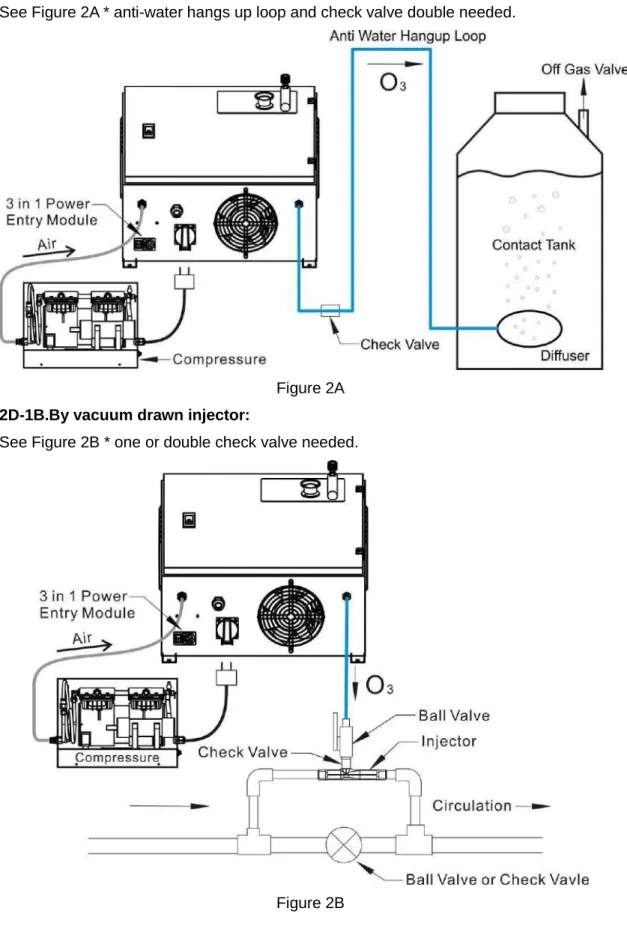
See Figure 2A * anti-water hangs up loop and check valve double needed.
Figure 2A
2D-1B.By vacuum drawn injector:
See Figure 2B * one or double check valve needed.
Figure 2B
2D-1C.By centrifugal air blower:
CTO-10 & CTO-20 OZONE GENERATOR
5
Figure 2C
2D-2: Plumbing for air pump
Use 8mm OD compress hose to connect both compress air inlet connector location on the
left of ozone generator„s bottom and compress air outlet connector location on the left side of air pump‟s bracket .
CTO-10 & CTO-20 OZONE GENERATOR
6
SECTION 3
Operation
3A.General
After mounting, plumbing wire and pipe please check again: 1.mounting 2.plumbing wire 3.plumbing pipe 4.and some necessary check.
3B. Normal Operation
Switch on main power switch location on the control panel. Generator cooling fans will start up and the oxygen concentrator and extra air pump will begin operating. The green
lamp location on the control will illuminate. Then turn ozone output adjustable knob as clockwise to the position you wanted while the red lamp will illuminate and you reference voltage meter will turn to suitable level, turn the knob location on the flow meter, let float position at 5L/min level (read top of float), reaction pressure gauge will turn on the position around 6PSI (if heavy fluctuating it means unusual, please read trouble shooting section). Ozone gas will produce.
Figure 3A
3C. System Shut-Down
3C-1.Ozone generator Shut-Down:
Turn ozone output adjustment knob anticlockwise to “0” and then turn main power switch
off .Red ozone output indicate lamp will turn off , green main power indicate lamp will turn off , extra air pump shut down .
3C-2.Applied System Shut-Down: 3C-2A.For positive pressure diffuser
Operate as step 3C-1
3C-2B.For vacuum drawn injector:
Operate first as step 3C-1, and then turn off water circulation pump.
3C-2C.For centrifugal air blower:
CTO-10 & CTO-20 OZONE GENERATOR
7
SECTION 4
Maintenance and Service
4A.System Electro-Mechanical Overview
Refer to Figure 4 for component locations.
Figure 4
This figure is only show the inside of the CTO-10. CTO-20 has two ozone modules.
4A-1. Indicator Lights
1. Main Power: Green light indicates that power is being supplied to the ozone generator. Air pump should be running.
2. Ozone Power: Red light indicates that power is being supplied to the high voltage Corona Discharge circuits and that ozone is being produced.
4A-2.Meters and gauge
1. Flow meter: Indicate the gas flow through out generator; the flow can be set by turning knob location on the flow meter (For CTO-10&20 flows setting at 5l/min)
2. Reference meter: Indicate ozone output level by your setting, reference as voltage shown.
3. Reactor pressure gauge: Indicate oxygen output pressure (for CTO-10&20 shown around 6PSI, for big different from 6PSI, please read trouble shooting section)
4A-3. Internal Components
1. Corona Discharge (CD) Module:
The generator module consists a quartz glass tube inner has a SS film sheet as a high voltage electrode which supported by SS brush, covered by an outlet earth electrode SS tube that clamped by a pair of Aluminum heat sink. It receives oxygen gas from PSA
CTO-10 & CTO-20 OZONE GENERATOR
8
oxygen module to produce ozone for output.
2. Power supply:
Power supply consists of a step down transformer, rectifier PCB and voltage regulator PCB. It reduces and regulates line AC voltage and rectifies to low DC voltage to supply drive module.
3. Drive module:
Drive module is fuse protected and it consists of a high voltage transformer and a drive PCB. It receives low DC voltage from power supply and change DC voltage to high frequency high voltage to supply ozone Corona Discharge (CD) Module to produce ozone gas.
4. Air pump:
Air pump consists of a piston type oil less pump, an air intake filter and muffler, coil type after cooler, air pump cooling fan, compress air safety relief valve. It supplies compress air to PSA oxygen concentration module.
5. Oxygen Concentration module:
Oxygen concentration module consists a pair of molecular sieve beds, a motorized distribution valve, an oxygen gas storage tank and an oxygen gas pressure regulate valve. It receives compress air from air pump to produce concentrated oxygen gas to supply ozone module.
6. Cooling fan:
Cooling fan cools internal components, it runs when main power switch turned on.
4B.Preventative Maintenance Schedule
The BODYCARE ozone system requires very little maintenance in normal use condition.
DAILY:
1. Check ozone generator for proper operation.
1a. Make sure red and green indicator light is illuminated. 2b. Make sure reference meter is indicating.
3b. Make sure flow meter is indicating proper air flow. (5L/min)
2. Check applied system:
2a. Check positive diffusion system, 2b. Check vacuum injection system 2c. Check centrifugal blower system
MONTHLY:
1. Shut off ozone generator.
2. Clean inside and outside generator 2a. Use compresses air spraying; 2d. Use dry & soft cloth cleaning; 2c. Use the bush brushing
Dust on the face of inner components. 3. Clean air pump
3a. Cleaning outface of air pump
CTO-10 & CTO-20 OZONE GENERATOR
9
BIANNUALLY:
1. Rebuild air pump. 2. Rebuild CD module. All see appendix A&B section.
4C.Trouble Shooting
An electrician who is trained by Bodycare Ozone Tech is required for trouble shooting. Contact a certified electrician if you are unsure of your ability to service the equipment. Improper servicing will void generator warranty.
Symptom: “Main power” light out when system is on.
1. No power to the generator from the power source: a. Check main fuse and replace if necessary
b. Check circuit breaker at the power distribution box and reset if necessary.
c. Check for loose connections or wiring breaks from the power distribution box to the generator and rebuild if necessary.
2. G.F.C.I. has tripped.*
a. Check power cord and reset G.F.C.I.
If G.F.C.I. or breaker continues to trip after reset, call for technical support.
Symptom:
Main power illuminates but extra air pump not runs.
1. Check the air pump‟s plug if properly to connect with socket that location at bottom of the generator. Check the starting capacitance state.
See as appendix “A”.
2. Air pump‟s temperature limited switch active (it means high ambient temperature, pump
will run again when temperature down.)
3. Air pump‟s starting capacity failure and replace if necessary
Symptom:
“Ozone output” indicator light out.
Power supply is failure, and sees as appendix “C”.
Symptom: CD Module is not operating. Ozone output has dropped. 1. No power to the generator module from the power supply:
a. Check fuse location on the ozone module‟s PCB, replace if necessary. b. Check H.V. cables for breaks or loose connections, replace if necessary. c. Check H.V. transformer, replace if necessary.
d. Check PCB location on the CD module, replace if necessary.
2. Water have been back into CD cell, get water out and use dry oxygen gas spray for more than 8hr for inner drying.
3. CD cell failure, replace if necessary. See as appendix “B”.
*CAUTION: HIGH VOLTAGE
Symptom: No air flow through the generator. The air flow meter indicates 0 L/min flow. 1. Check all tube/hose connection, if loosing or leaking please rebuild
CTO-10 & CTO-20 OZONE GENERATOR
10
2. Adjustable valve location on flow meter is shut off, reopen if necessary, 3. PSA oxygen module failure, replace (rebuild) if necessary. See appendix “D”
SECTION 5
Replacement Parts
5A. Standard replacement parts list:
1. OP-1 oil less air pump for CTO-10/20 AP-157 2. CD ozone module
CTO-10 (one required) CD-141
CTO-20(two required) CD-151
3. PSA oxygen module
CTO-10/20 (one required) OM-127
4. Power supply module
CTO-10/20 (one required). PS-124
5. Flow meter
CTO-10/20 (one required) FM-136
6. Oxygen pressure gauge
CTO-10/20 (one required) PG-161
7. Reference meter
CTO-10/20 (one required) RM-174
8. Cooling fan
CTO-10/20 (one required) CF-168
9. Tubing (hose)
Tubing for compressor air TC-138
Tubing for oxygen gas TA-193
CTO-10 & CTO-20 OZONE GENERATOR
11
Appendix: “A”
CTO-10 & CTO-20 OZONE GENERATOR
12
Appendix: “B”
CD Ozone Module
CTO-10 & CTO-20 OZONE GENERATOR
13
Appendix: “C”
PSA Oxygen Module
Appendix: “D”
CTO-10 & CTO-20 OZONE GENERATOR
1
CTO-10 & CTO-20 OZONE GENERATOR
2