© 2019, IRJET | Impact Factor value: 7.211 | ISO 9001:2008 Certified Journal
| Page 1609
A Study on Performance of High-Rise Building with Different Structural
Systems under Earthquake Loading Condition
Vaishakh S
1, Dr. H Eramma
2, Madhukaran
31
PG Student (CADS), Dept. of Studies in Civil Engineering, University BDT College of Engineering,
Davanagere-577004, Karnataka, India
2
Associate Professor, Dept. of Studies in Civil Engineering, University BDT College of Engineering,
Davanagere-577004, Karnataka, India
3
Assistant Professor, Dept. of Studies in Civil Engineering, University BDT College of Engineering,
Davanagere-577004, Karnataka, India
---***---Abstract- Earthquake is one of the terrifying and damaging phenomena of nature and the after effects are terrible. To resist the earthquake loads, in this new era in the field of civil engineering design and construction a vital improvement in new technologies has under gone. In this study a G+20 storey building is considered for modelling and analysis is done with different structural systems like Beam slab, Flat slab and Flat plate system along with Shear wall as well as Bracings. ETABS 2016 is used for analysis of 28 individual models at all seismic zones as per IS 1893:2002. Result has been obtained parameters like time period, base shear, storey displacement and storey drift. From the result can concluded that beam slab system having storey displacement of 47% and storey drift of 50% is more than the any other structural systems in analysis. The time period is 53% lesser in flat plate with shear wall and flat plate with bracing system compare to beam slab and flat slab systems, because of less flexibility. The base shear is maximum at flat slab with shear wall system, where it is 34% more than beam slab system, 70% more than flat slab, 2% more than the flat slab with bracing, 80% more than flat plate, 5% more than flat plate with shear wall and 8% more than flat plate with bracings systems.
Key Words: Beam slab, Flat slab, Flat plate, Shear wall, Bracing, time period, base shear, storey displacement, storey drift.
1. INTRODUCTION
In the recent 20 year throughout the world Tall Structures had been developed and the counting numbers speedily increased. In-term to skip from the use of dampers, shear wall and many other things and eventually over the utilization of material which are used for construction of tall structure required skill in occupancy comfort, design condition may different, improvement were needed in design and use than present existence structures of a specific range and period is recognized as the elevated structure. Discovering new structural systems can be the described as either the flexural or the shear structures that transmit over powering weights from column or walls catching up on its top and redistribute them to supporting column or walls. Such discovering structural systems may be as Flat slab or Flat plates. A sensible design, accurate analysis, preparatory design and upgrade, to safely pass on gravity and lateral
loads are the blue-print of the tall structures. Quality, the serviceability, stiffness and human comfort are the configuration criteria. Many Structural systems were introduced to meet the demand of Tall buildings except Conventional type of construction methods with the co-operation of bracings and shear wall.
2. BEAM SLAB (CONVENTIONAL) SYSTEM
This system comprises of slab, beam and column. It is a very traditional system. In which slab rested on beam which transfers entire load into the Column thus it equally distributed underneath of structure through footing. However, the complications of beam formwork, co-ordination of services, and overall depth of the floor have led to a decrease in the popularity of this type of floor.
3. FLAT SLAB SYSTEM
Common practice of design and construction beam-slab construction where the beams reduce the available net clear ceiling height. Hence in Commercial malls, offices and public halls sometimes beams are avoided and slabs are directly supported by columns. This type of construction is aesthetically appealing also. These slabs which are directly supported by columns are called flat slabs. Now a days this type of construction of RC buildings with flat slab systems has become widely used in India for Commercial Buildings
4. FLAT PLATE SYSTEM
Flat Plates are solid concrete slabs of uniform depths that transfer loads directly to the supporting columns without beams or capitals or drop panels. Flat plates are probably the most commonly used slab system today for multi-storey reinforced concrete hotels, apartment houses, hospitals & malls. The accurate design consideration has to be done for design of flat plate and flat slab due to lack of resistance to lateral loads, hence special features like shear walls, bracings are to be taken into consideration.
5. LINEAR STATIC1ANALYSIS
© 2019, IRJET | Impact Factor value: 7.211 | ISO 9001:2008 Certified Journal
| Page 1610
design horizontal seismic coefficient and seismic weight of the structure. Design horizontal seismic coefficient depends on the zone factor of the site, importance of the structure, response reduction factor of the lateral load resisting elements and the fundamental period of the structure.
6. OBJECTIVES
1. To know the behaviour of high-rise building with three different structural systems.
2. To study the lateral load resisting capacity of different structural systems.
3. To observe the seismic behaviour of RCC building in considered all Four different seismic zones.
4. Finding out the storey displacement, story drift, fundamental time period, base shear.
5. To obtain an effective and Economical structural system to resist the lateral load per Earthquake Zones.
7. MODELLING AND ANALYSIS
7.1 ETABS
The entire analysis has done for all the 3D models using ETABS 16.2 non-linear version software. The results are tabulated in order to focus the parameters such as fundamental time period, base shear, storey displacement and storey drift.
7.2 Model Description
Grade of steel Fe 500
Grade of concrete M30
Height between floors 3.0 m
Columns 230x450 mm, 230x600 mm,
230x1000 mm & 800x800 mm.
Beams 230x600 mm, 230x450 mm
Concrete Bracings 250x250mm
Conventional slab 150 mm
Flat Slab 150 mm
Flat Slab drop 200 mm
Flat Plate 125 mm
Shear Wall 200 mm
Earthquake Zones Ⅱ, Ⅲ, Ⅳ & Ⅴ
Earthquake Zone Factor 0.1,0.16,0.24 & 0.36
Soil Type Medium Soil
Response Reduction R 3
Importance Factor I 1
Totally 28 individual models were done in this analysis
7.3 Plan and 3d View of Models
[image:2.595.310.557.227.407.2]Fig 1:Typical Floor Plan of G+20 Building
[image:2.595.359.509.448.644.2]© 2019, IRJET | Impact Factor value: 7.211 | ISO 9001:2008 Certified Journal
| Page 1611
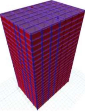
[image:3.595.77.246.313.483.2]Fig 3: ETABS model in 3-D view of Flat Slab system
[image:3.595.357.511.332.508.2]Fig 4: ETABS model in 3-D view of Flat Plate System
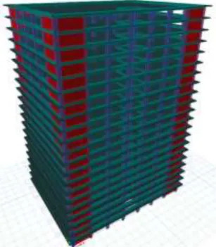
Fig 5: ETABS model in 3-D view of Flat Slab with shear wall system
[image:3.595.78.243.520.709.2]Fig 6: ETABS model in 3-D view of Flat Slab with Bracing system
Fig 7: ETABS model in 3-D view of Flat Plate with shear wall system
[image:3.595.352.514.556.736.2]© 2019, IRJET | Impact Factor value: 7.211 | ISO 9001:2008 Certified Journal
| Page 1612
8. RESULTS AND DISCUSSION
[image:4.595.33.290.332.577.2]8.1 Time period
Fig 9. Time Period of All Structural Systems along X and Y directions.
The time period is 53% lesser in Flat Plate with Shear wall & Flat Plate with Bracing system compare other systems.
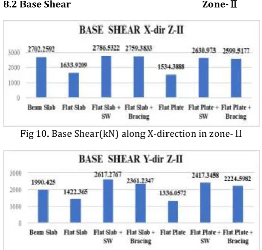
8.2 Base Shear Zone-Ⅱ
Fig 10. Base Shear(kN) along X-direction in zone-Ⅱ
Fig 11. Base Shear(kN) along Y-direction in zone-Ⅱ
Zone-Ⅲ
Fig 12. Base Shear(kN) along X-direction in zone-Ⅲ
Fig 13. Base Shear(kN) along Y-direction in in zone-Ⅲ
Zone-Ⅳ
Fig 14. Base Shear(kN) along X-direction in zone-Ⅳ
Fig 15. Base Shear(kN) along Y-direction in zone-Ⅳ
Zone-Ⅴ
Fig 16. Base Shear(kN) along X-direction in zone-Ⅴ
© 2019, IRJET | Impact Factor value: 7.211 | ISO 9001:2008 Certified Journal
| Page 1613
Base shear is maximum at Flat Slab with Shear wall system, where it is 34% more than Beam Slab system, 70% more than Flat slab, 2% more than Flat slab with Bracing, 80% more than Flat plate, 5% more than Flat plate with Shear wall and 8% more than Flat plate with Bracings Systems.
[image:5.595.310.562.109.226.2]8.3 Maximum Storey Displacement Zone-Ⅱ
[image:5.595.38.561.123.765.2]Fig 18. Maximum Storey Displacement in Zone–II for X Direction
Fig 19. Maximum Storey Displacement in Zone–II for Y Direction
Zone-Ⅲ
Fig 20. Maximum Storey Displacement in Zone–Ⅲ for X Direction
Fig 21. Maximum Storey Displacement in Zone–Ⅲ for Y Direction
Zone-Ⅳ
Fig 22. Maximum Storey Displacement in Zone–Ⅳ for X Direction
Fig 23. Maximum Storey Displacement in Zone–Ⅳ for Y Direction
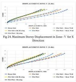
[image:5.595.34.290.177.576.2]Zone-Ⅴ
Fig 24. Maximum Storey Displacement in Zone–Ⅴ for X Direction
Fig 25. Maximum Storey Displacement in Zone–Ⅴ for Y Direction
[image:5.595.306.560.430.702.2]© 2019, IRJET | Impact Factor value: 7.211 | ISO 9001:2008 Certified Journal
| Page 1614
other models. And we can notice that, where it is 40% lesser than other systems.
[image:6.595.306.561.93.358.2]8.4 Maximum Storey Drift Zone-Ⅱ
Fig 26. Maximum Storey Drift in Zone–II for X Direction
Fig 27. Maximum Storey Drift in Zone–II for Y Direction
[image:6.595.38.291.143.274.2]Zone-Ⅲ
Fig 28. Maximum Storey Drift in Zone–Ⅲ for X Direction
Fig 29. Maximum Storey Drift in Zone–Ⅲ for Y Direction
[image:6.595.36.290.303.416.2]Zone-Ⅳ
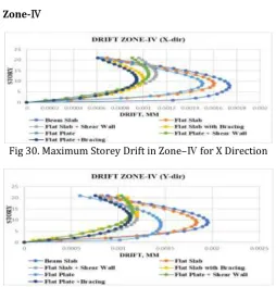
[image:6.595.311.558.385.527.2]Fig 30. Maximum Storey Drift in Zone–Ⅳ for X Direction
Fig 31. Maximum Storey Drift in Zone–Ⅳ for Y Direction
Zone-Ⅴ
Fig 32. Maximum Storey Drift in Zone–Ⅴ for X Direction
Fig 33. Maximum Storey Drift in Zone–Ⅴ for Y Direction
[image:6.595.38.287.449.579.2] [image:6.595.311.555.560.680.2] [image:6.595.40.286.612.733.2]© 2019, IRJET | Impact Factor value: 7.211 | ISO 9001:2008 Certified Journal
| Page 1615
CONCLUSIONS
1. The time period is 53% lesser in Flat Plate with Shear wall & Flat Plate with Bracing system compare to Beam Slab & Flat Slab systems.
2. Base shear is maximum at Flat Slab with Shear wall system, where it is 34% more than Beam Slab system, 70% more than Flat slab, 2% more than Flat slab with Bracing, 80% more than Flat plate, 5% more than Flat plate with Shear wall and 8% more than Flat plate with Bracings Systems.
3. Because of high flexibility in Beam slab & Flat slab systems the maximum lateral storey displacement is 47% more as compare to other systems.
4. It is found that Lateral displacement is minimum at plinth level and most at terrace level, because the variety of stories will increase lateral displacement additionally exaggerated by 25%.
5. Maximum Storey drift is obtained lesser in Flat plate with Bracings system, where it is 50% lesser than Beam slab and other systems.
6. By this study comparing Time period, Displacement, Drift and Base shear we can conclude that, Flat Plate with Bracing system is the most economical structural system compared to other systems,
ACKNOWLEDGEMENT
The authors wish to thank the authorities of Visveswaraya Technological University, Belgaum for giving an opportunity to conduct an analytical work in the CAD laboratory of University B.D.T College of engineering. Davangere-577004.
REFERENCES
[1] Mohana H.S, Kavan M.R, ” Comparative Study of Flat Slab
and Conventional Slab Structure Using ETABS for Different Earthquake Zones of India” International Research Journal of Engineering and Technology, e-ISSN: 2395 -0056, p-e-ISSN: 2395-0072 Volume: 02 Issue: 03 June-2015.
[2] Durgesh Neve1, R. P. Patil, “Survey Paper on Analysis of
Flat Slab Resting on shear walls” International Research Journal of Engineering and Technology, eISSN: 2395 -0056, p-ISSN: 2395-0072 Volume: 03 Issue: 05
May-2016.
[3] Rameshkumar H Mali and Shreepad Desai “Performance
of Flat Slabs & Flat Plates in High Seismic Zone with Varying Stiffness” IRJET 2018 p-ISSN:2395-0072.
[4] Navyashree K and Sahana T S,“Use of flat slabs in
multistory commercial building situated in high seismic zone”, International Journal of Research in Engineering and Technology e-ISSN: 2319-1163 pISSN:t2321-7308
[5] Pradip S. Lande and Aniket B. Raut, “Seismic Behaviour
of Flat Slab Systems”, Journal of Civil Engineering and Environmental Technology Print ISSN: 2349-8404; Online ISSN: 2349-879X.
[6] Bindu N Byadgi, Vijayalakshmi R, Dr. Jagadish Kori
“Behavior of Flat Slab by Varying Stiffness in High Seismic Zone” International Research Journal of the Engineering and Technology, e-ISSN:2395-0056, p-ISSN: 2395-0072.
[7] Manu K V, Naveen Kumar B M, Priyanka S “Comparative
Study of Flat Slabs and Conventional RC Slabs in High Seismic Zone” IRJET 2015 p-ISSN:2395-0072
[8] Prerana Nampalli, Prakash Sangave,“Linear and Non
Linear Analysis of Reinforced Concrete Frames with Members of Varying Inertia”, IOSR Jurnals of Mechanical and Civil Engineering e-ISSN:2278-1684
[9] R.S.More, V.S.Sawant, “Analysis of Flat slab”,
International Research Journal of Science and research (IJSR), IISN:2319-7064
[10] DurgeshyNeve, R. P.Patil, “Investigation of Hospital
Building by replacing column by Shear walls”, International Journal of Research in Engineering and Technology eISSN: 2315-1185
[11] Srinivasulu P, Dattatreya Kumar, “Behavior of RCC flat
slab structure under earthquake loading”, International Journal of Engineering and Science Research
[12] Rame Gowda M and Techi Tata, “Study of Seismic