Development of a graded index
microlens based fiber optical trap and its
characterization using principal
component analysis
J. Nylk∗1,2, M. V. G. Kristensen1, M. Mazilu1, A. K. Thayil1,2, C. A. Mitchell1,2, E. C. Campbell2, S. J. Powis3, F. J. Gunn-Moore2, K.
Dholakia1
1SUPA, School of Physics and Astronomy, University of St Andrews, St Andrews, KY16 9SS,
UK
2School of Biology, University of St Andrews, St Andrews, KY16 9TF, UK 3School of Medicine, University of St Andrews, St Andrews, KY16 9TF, UK
Abstract:
We demonstrate a miniaturized single beam fiber optical trapping probe based on a high numerical aperture graded index (GRIN) micro-objective lens. This enables optical trapping at a distance of 200µm from the probe tip. The fiber trapping probe is characterized experimentally using power spectral density analysis and an original approach based on principal component analysis for accurate particle tracking. Its use for biomedical microscopy is demonstrated through optically mediated immunological synapse formation.
© 2015 Optical Society of America
OCIS codes:(060.2310) Fiber optics; (110.2760) Gradient-index lenses; (170.0170) Medi-cal optics and biotechnology; (170.3880) MediMedi-cal and biologiMedi-cal imaging; (170.4520) OptiMedi-cal confinement and manipulation; (180.0180) Microscopy; (180.2520) Fluorescence microscopy; (350.4855) Optical tweezers or optical manipulation.
References and links
1. T. T. Perkins, “Optical traps for single molecule biophysics: A primer,“ Laser & Photon. Rev.,3(1-2), 203–220 (2009).
2. K. Dholakia, P. Reece, and M. Gu, “Optical micromanipulation,“ Chem. Soc. Rev.,37(1), 42–55 (2008). 3. A. Hoffmann, G. Meyer zu H¨orste, G. Pilarczyk, S. Monajembashi, V. Uhl, K. O. Greulich, “Optical tweezers
for confocal microscopy,“ Appl. Phys. B,71(5), 747–753 (2000).
4. M. Yevnin, D. Kasimov, Y. Gluckman, Y. Ebenstein, Y. Roichman, “Independent and simultaneous three-dimensional optical trapping and imaging,“ Biomed. Opt. Express,4(10) 2087-2094 (2013).
5. M. Goks¨or, J. Enger, and D. Hanstorp, “Optical manipulation in combination with multiphoton microscopy for single-cell studies,“ Appl. Opt.,43(25), 4831–4837 (2004).
6. I. Heller, G. Sitters, O. D. Broekmans, G. Farge, C. Menges, W. Wende, S. W. Hell, E. J. G. Peterman, and G. J. L. Wuite, “STED nanoscopy combined with optical tweezers reveals protein dynamics on densely covered DNA,“ Nat. Methods,10(9), 910–916 (2013).
7. Z. Liu, C. Guo, J. Yang, and L. Yuan, “Tapered fiber optical tweezers for microscopic particle trapping: fabrica-tion and applicafabrica-tion,“ Opt. Express,14(25), 12510-12516 (2006).
8. G. Brambilla, and F. Xu, “Adiabatic submicrometric tapers for optical tweezers,“ Electron. Lett.,43(4), 204-206 (2007).
10. Y. Gong, A. Y. Ye, Y. Wu, Y. J. Rao, Y. Yao, and S. Xiao, “Graded-index fiber tip optical tweezers: Numerical simulation and trapping experiment,“ Opt. Express,21(13), 16181-16190 (2013).
11. Y. Gong, W. Huang, Q. F. Liu, Y. Wu, Y. J. Rao, G. D. Peng, J. Lang, and K. Zhang, “Graded-index optical fiber tweezers with long manipulation length,“ Opt. Express,22(21), 25267-25276 (2014).
12. T. ˇCiˇzm´ar, and K. Dholakia, “Shaping the light transmission through a multimode optical fibre: complex trans-formation analysis and applications in biophotonics,“ Opt. Express,19(20), 18871-18884 (2011).
13. W. H¨ubner, G. P. McNerney, P. Chen, B. M. Dale, R. E. Gordon, F. Y. S. Chuang, X. D. Li, D. M. Asmuth, T. Huser, and B. K. Chen, “Quantitative 3D video microscopy of HIV transfer across T cell virological synapses,“ Science,323(5922), 1743-1747 (2009).
14. A. Grakoui, S. K. Bromley, C. Sumen, M. M. Davis, A. S. Shaw, P. M. Allen, and M. L. Dustin, “The immuno-logical synapse: a molecular machine controlling T cell activation,“ Science,285(9), 221-227 (1999). 15. S. Oddos, C. Dunsby, M. A. Purbhoo, A. Chauveau, D. M. Owen, M. A. A. Neil, D. M. Davis, and P. M. W.
French, “High-speed high-resolution imaging of intercellular immune synapses using optical tweezers,“ Biophys. J.,95(10), L66-L68 (2008).
16. X. Wei, B. J. Tromberg, and M. D. Cahalan, “Mapping the sensitivity of T cells with an optical trap: Polarity and minimal number of receptors for Ca(2+) signaling,“ Proc. Natl. Acad. Sci. USA,96(15), 8471-8476 (1999). 17. J. C. Shane, M. Mazilu, W. M. Lee, and K. Dholakia, “Effect of temporal shape on optical trapping and impulse
transfer using ultrashort pulsed lasers,“ Opt. Express,18(7), 7554-7568 (2010).
18. M. Turk, and A. Pentland, “Eigenfaces for Recognition,“ J. Cog. Neurosci.,3(1) 71-86 (1991).
19. M. Guizar-Sicairos, S. T. Thurman, and J. R. Fienup, “Efficient subpixel image registration algorithms,“ Opt. Lett.,33(2), 156-158 (2008).
20. K. Berg-Sørensen, and H. Flyvbjerg, “Power spectrum analysis for optical tweezers,“ Rev. Sci. Instrum.,75, 594 (2004).
21. T. B. Lindballe, M. V. Kristensen, A. P. Kylling, D. Z. Palima, J. Gl¨uckstad, S. R. Keiding, and H. Stapelfeldt, “Three-dimensional imaging and force characterization of multiple trapped particles in low NA couterpropagat-ing optical traps,“ J. Eur. Opt. Soc., Rapid Publ.,6, 11057 (2011).
22. K. Svoboda, and S. M. Block, “Biological applications of optical forces,“ Annu. Rev. Biophys. Biomol. Struct., 23, 247-85 (1994).
23. J. M. Tam, C. E. Castro, R. J. W. Heath, M. L. Cardenas, R. J. Xavier, M. J. Lang, and J. M. Vyas, “Control and manipulation of pathogens with an optical trap for live cell imaging of intercellular interactions,“ PloS ONE, 5(12), e15215 (2010).
24. C. H. June, J. A. Bluestone, L. M. Nadler, and C. B. Thompson, “The B7 and CD28 receptor families,“ Immunol. Today,15(7), 321-331 (1994).
1. Introduction
The short manipulation length of many fiber optical traps results in the fiber probe itself contributing strongly to images of trapped objects. This can interfere with measurements for characterization of the optical trap. With careful design, the imaging system may be optimized to minimize the influence of the probe on images of trapped objects. When trapping probes are combined with sophisticated or specialized optical microscopes for biophysical studies, this optimization may not be possible for characterization of the trap due to additional constraints on the imaging system.
In terms of biophysical applications, understanding cell-cell interactions is becoming in-creasingly important in, for example, the study of viral transfer [13] and the immune system [14]. Presently, many such studies offer little spatio-temporal control of the sample and inter-action events cannot be triggered on a cell selective basis. A full understanding is formed from sampling many events at various stages of interaction and inference of the true evolution. As such, optical traps can be employed to trigger interaction events and follow the full temporal evolution of a single synapsein toto[15, 16]. Notably, two-dimensional optical traps often offer sufficient manipulation for these studies.
In this paper we demonstrate the use of a fiber coupled GRIN lens geometry for an ultra-facile and powerful two-dimensional optical trap. All optical components of the fiber trapping probe are commercially available. By utilizing a fiber mounted micro-objective we combine the advantages of a fiber probe based trapping system with a long working distance. A key attribute of our system is the integration of our trap with sophisticated microscopes without the need to access any port. The addition of the trapping probe does not inhibit the high quality fluores-cence imaging capability of the microscope. The fiber optical trapping probe is characterized by power spectral density analysis utilizing an original adaptive image filtering method based on principal component analysis (PCA) to counteract deleterious image artifacts resulting from re-flections from the fiber probe and facilitate accurate tracking of the trapped particle. Finally, the potential of our probe for biophysics applications is demonstrated by its use to selectively and controllably induce immunological synapse formation between a T-cell and a polystyrene bead coated with activating antibodies. To the best of our knowledge, this is the first demonstration of the use of an optical fiber trapping probe for the manipulation of immune cells.
2. Experimental set-up
Imagenw.d. =n200μm
Objectnw.d. =n200μm
Laser
SMF
EMCCD M
FC2 FC1 Obj
SMA SMF
GRIN Lens (b)
[image:4.612.150.467.83.163.2](a)
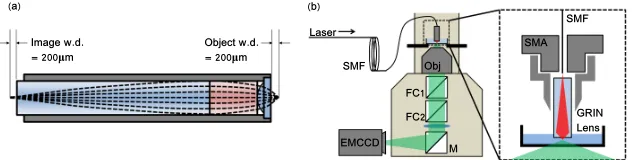
Figure 1. Schematic of the GRIN microlens (a) and the fiber optical trapping probe inte-grated into a commercial fluorescence microscopy platform (b). (a) shows ray optics propa-gation (dashed lines) through the GRIN lens and theoretical image and object working dis-tances (w.d.). (b) shows the fiber probe mounted on an inverted microscope. Insert shows detail of fiber-GRIN lens adapter. SMF: single-mode fiber, Obj: objective lens, FCx: filter cubes, M: mirror, EMCCD: electron multiplied charge coupled device, SMA: SMA fiber connector.
The fiber trapping probe was mounted on an inverted microscope (Nikon, Eclipse Ti) above the sample as shown in Fig. 1(b), by attaching onto the mount traditionally reserved for a condenser lens when using brightfield illumination. The probe was positioned using thexyz positioning screws which move the condenser lens mount and az-axis micrometer positioning stage (Thorlabs, SM1Z) was used for fine adjustment to ensure the trap focus was in the image plane of the microscope. Fluorescence excitation is provided through the top tier of microscope ports and appropriate choice of excitation and emission filters in filter cube 1, fluorescence was collected by a 0.8 NA, 60X objective lens (Nikon, CFI 60X) onto an electron multiplied charge coupled device (EMCCD, Andor, iXon+). The only modification to the microscope required to use the probe is the addition of a filter which protects the camera from the high intensity trap beam (Semrock, FF01-650/SP-25). A fast CCD camera (Basler, piA640-201gm) mounted in a secondary microscope camera port enabled characterization of the particle motion.
To evaluate the focusing ability of the GRIN micro-objective lens, the tip of the probe was immersed in water and an image stack was acquired around beam focus. The optic axis of the trap beam was offset from the optic axis of the microscope by 10◦. Intensity profiles were taken through the focus. Full width at half maximum (FWHM) values gave the lateral beam widths along thex- andy-axes to be(1.3±0.1)µm and(1.9±0.1)µm respectively. The axial beam width was(6.4±0.3)µm. We attribute the tilt and thex−yasymmetry of the trap beam to a minor misalignment between the fiber tip and the GRIN lens.
3. Results and Discussion
3.1. Characterization of the optical trap
As the trap geometry does not permit brightfield illumination, and to avoid any artifacts from using trapped fluorescent particles [17], we resorted to an alternative approach for imaging. As such, we place a half mirror in filter cube 1 to facilitate reflection imaging of non-fluorescent microspheres. Imaging and tracking of the trapped particles was performed using the fast CCD camera which facilitated 400Hz acquisition rates with a 60x60 pixel region of interest. The trap stiffness was determined through the power spectral density method. For our probe, 400Hz is above the Nyquist sampling rate for observing the trap corner frequency. Movies of 100s dura-tion were recorded for polystyrene beads of(3.00±0.02)µm, and(4.17±0.03)µm diameter (Polysciences Inc., 64060, 64070 respectively) and for a range of powers. The temperature of the microscope stage was kept constant at(25.6±0.2)◦C during the experiment.
contribute significantly to the image resulting in noise (see Fig. 2(a)) that requires very specific image manipulation and thresholding before accurate tracking can be achieved. To aid image processing, we incorporate an adaptive filter based upon principal component analysis (PCA) into our image filtering procedure to remove strong stochastic noise. The adaptive nature of the filter reduces the reliance on subjective, user specified filtering procedures. Our image filtering procedure is exemplified in Fig. 2(a-d).
The adaptive filter determines the first few principal components (PCs) in the spatial domain taking into account all the individual frames of the movie. These PCs are akin to the eigenfaces used in facial recognition [18] and describe the main variations between individual frames. As these variations are due to the motion of the particle in a trap, we have a direct relationship between the images of the first few PCs (3 in the case of Fig. 2) and the position of the particles. Each PC is, in a way, associated with a specific degree of freedom of the particle. In this case, the first PC contains the positional offset while the next two PCs are related to movements in thex−yplane. Higher order PCs typically account for random image fluctuations that do not contain any relevant data but occasionally some structure is observed most likely originating from minute particle asymmetries or motion of the particle beyond the first order linear image regime.
More precisely, we define the covariance matrix as
Ci j=
∑
n∑
mMnmi Mnmj (1)
whereMi
nm corresponds to the pixel value of thei−thframe of the tracking movie with the
subscriptsm andn defining the two dimensional pixel position. The summation is implied over all possible pixel indexes. In this context, the covariance matrix describes the correlations between framesiand j. The covariance matrix is a symmetric, positive, semi-definite matrix and can be represented by a set of real positive eigenvalues and corresponding eigenvectors
λ(k)Vi(k)=
∑
j
Ci jV
(k)
j (2)
whereλ(k)defines thek−theigenvalue andVi(k)the associated eigenvector. The different eigen-vectors are orthogonal to each other and the eigenvector associated with the largest eigenvalue defines the largest variation described by the frames of the movie. Usually the eigenvectors and eigenvalues are ordered in decreasing order and the largest eigenvalue corresponds then with the first eigenvalue. The image reconstructed using the first eigenvector defines the first PC in the frame space
Mi j(1)=√1
λ(k)
∑
mMi jmVm(k). (3)
The second or higher order PCs are defined using the second or higher order eigenvectors. Typically, the first few PCs account for most inter-frame variations.
The adaptive filter consists of projecting each individual frame onto the PCs of the movie
ck=
∑
n∑
mMnmj Mnm(k). (4)
The inverse process is then performed to reconstruct the individual frames using the first few PCs only.
˜ Mnmj =
kmax
∑
k=1
Principal[components[used[in[adaptive[filter
7dx
4th 5
th 6
th
1st 2nd 3rd
7bx 7cx
7ax
0 20 40 60 80 0
10 20 30 40 50
Power[[mW]
Fo
rce
[C
ons
tan
t[[
pN
/
μ
m
]
3.00μm 4.17μm x-axis
[image:6.612.146.469.76.174.2]7ex
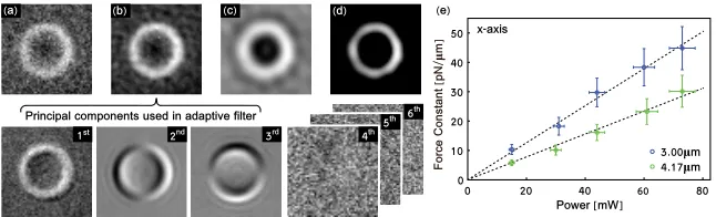
Figure 2. Illustration of the image filtering process and force characterization. (a) shows an original frame from a movie of a 3.00µm diameter bead trapped with 60mW. (b) shows the same frame as in (a)after the adaptive filter. The bottom row of images shows the first six PCs for the movie of which the first three are used in the adaptive filter. In this example, all PCs after the third contain only random noise. In (c) an additional bandpass filter has removed dead pixels and other small stationary objects. (d) shows the thresholded image, used for tracking. (e) shows force constants as a function of laser power along the
x-axis for 3.00 and 4.17µm diameter polystyrene beads. The force constants have a power dependence given byfx,3.00µm= (0.63±0.01)pN·µm−1·mW−1, andfx,4.17µm= (0.39±
0.01)pN·µm−1·mW−1for thex-axis, for 3.00 and 4.17µm diameter beads respectively.
Similar trends, fy,3.00µm= (0.522±0.006)pN·µm−1·mW−1, and fy,4.17µm= (0.35±
0.006)pN·µm−1·mW−1were determined for they-axis.
where the indexkmaxdefines the number of PCs considered which is restricted to the number of
important components accounting for most of the variations. The resulting images ˜Mnmj are free
of inter-frame fluctuations and contain only variations relevant to the motion of the particle. The number of PCs used in our experiments for the reconstruction contain(95±2)% of all the variations, typically only the first 3 PCs were used but when higher order PCs were utilized the first 3 PCs still contained (91±1)% of all variation. Fig. 2(b) shows the effect of this filter. Subsequently, a spatial band-pass filter is applied in the Fourier domain of each frame to remove the effect of small stationary objects such as dead pixels which are not removed by the adaptive filter as shown in Fig. 2(c). Finally, a simple threshold filter is used to remove remaining background noise as illustrated in the example frame in Fig. 2(d).
We validated the use of the adaptive filter in our image processing by tracking particles where the particle position was precisely known. Particles were immobilized on a glass coverslip un-der imaging conditions identical to those for the trap stiffness measurements and moved along known trajectories using a nanopositioning stage (PI, P-733.3DD). The trajectories determined by the tracking method were compared to the known trajectories. The standard deviation of the difference between the actual position and the result of tracking was 12nm.
Tracking of the trapped beads was achieved using a cross-correlation based sub-pixel image registration algorithm [19]. The power spectral density of each trace was determined and fitted with the Langevin equation [20] to obtain the corner frequency. An exponential distribution of the data was assumed [21] since low corner frequencies were observed which made windowing of the data impractical [20].
Faxen’s correction was included in the calculation of the drag coefficient for each trapped bead [22] where the height of the bead center, h, is defined as h=d/2+s, d is the bead diameter andsis the distance between the chamber floor and the bottom of the bead. Trapping occurred in close proximity to the chamber floor and we estimateds= (0.25±0.2)µm.
Time [s]
Sig
nal
[a
.u
.]
0.5 1.0
Co
ntr
ol
[a.
u.
]
0 50 100 150
0.8 1.0
Signal Control Exp. Fit (c)
(a)
Control Trapped Cell
(Signal) Bead
(b)
[image:7.612.153.465.76.207.2](d)
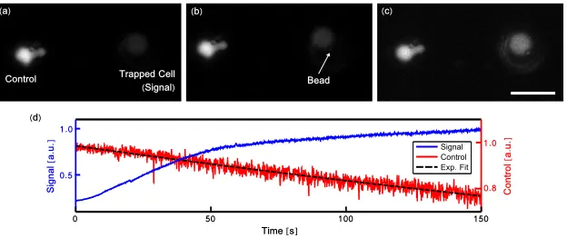
Figure 3. Selected video frames (a-c) showing an optically trapped T-cell (Signal), pre-loaded with Fluo-4, being positioned to form an immune synapse with an antibody coated bead. Frames show the image before (a), shortly after (b), and longer after (c) initial contact. Scale bar in (c) is 10µm. An adjacent cell (Control) is used to correct for photobleaching. (d) shows the increase in fluorescence signal from the trapped cell indicating increased calcium signaling and the formation of an immune synapse. An exponential curve (Exp. Fit) was fitted to confirm the decrease in intensity can be attributed to photobleaching.
3.2. Optically mediated immunosynapse formation
Cellular studies of the immune system have benefited from the addition of optical trapping due to the ability to control cell-cell interactions and follow the full temporal evolution of an indi-vidual synapse [15, 16]. Here we demonstrate the applicability of our probe to these studies by selectively inducing the formation of an immunological synapse. Synapse formation was trig-gered in B3Z cells, a murine hybridoma cell line, by contact with a polystyrene bead conjugated to the mouse antibodies; anti-CD3, which bypasses the T cell receptor (TCR) mechanism for direct activation of the T cell [16, 23], and anti-CD28, a co-receptor which ensures sustained synapse induction [24]. Immune synapse activity was detected by monitoring calcium signaling within the T cell.
Prior to the experiment, B3Z cells were loaded with the calcium indicator Fluo-4 (Life Technologies, Fluo-4, AM, cell permeant, F-14201) as per manufacturer’s instructions. The cells were resuspended in phenol-red free Dulbecco’s modified Eagle’s medium and plated out into a 35mm fluorodish (World Precision Instruments, FD3510-100) and the antibody coated polystyrene beads added. Antibody conjugated beads were prepared by passive adsorption of 3.1µm polystyrene beads coated with protein G (0.5% (w/v), Spherotech, PGP-30-5) with mouse anti-CD3 (1mg/mL, eBioscience, 0032) and anti-CD28 (1mg/mL, eBioscience, 16-0281) antibodies.
4. Summary and Conclusions
A novel miniaturized single beam fiber optical trapping probe based on a GRIN micro-objective lens has been demonstrated. It has been characterized by power spectral density analysis based upon a novel adaptive image filtering method based on principal component analysis. The appli-cability of the fiber probe has been shown through its integration into a commercial fluorescence microscope, and the potential impact for biophysics studies has been highlighted by using the fiber probe for controlled, optically mediated immune synapse formation.
At present a static optical trap is produced however, more sophisticated beam launch mech-anisms may exploit the GRIN micro-objective to deliver multiple and dynamic optical traps. Higher NA launch mechanisms, such as complex beam shaping through a multi-mode fiber, may also facilitate full three-dimensional optical trapping which would be beneficial for a num-ber of applications.
The adaptive nature of the PCA image filter reduces the effect of user-subjectivity when processing data for determination of optical trap strength. Although this technique is most ef-fective in a high noise environment as found near the tip of a fiber probe, image filtering by PCA may be applied to any image based method for particle tracking or optical trap strength determination.
We foresee the integration of the fiber probe with more sophisticated microscope platforms, for example super-resolution microscopes, which would enable more advanced studies of the immunological synapse and other cell-cell interactions.
Acknowledgements